Series 955 Tech Set storefront Installation Instructions Part NO.
TABLE OF CONTENTS PAGE SECTION I GENERAL NOTES AND GUIDELINES 1-2 II PARTS IDENTIFICATION 3-5 III DRILL JIGS DRILL JIG GUIDES 6-7 8-11 IV FABRICATION 12-21 V ASSEMBLY 22-26 VI FRAME INSTALLATION 27-30 VII GLASS INSTALLATION 31-39 VIII DOOR FRAME INSTALLATION 40-43 Minimizing Condensation NOTE: Please reference EFCO's "Understanding Condensation" brochure which can be obtained through your EFCO representative.
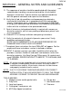
SECTION I - GENERAL NOTES AND GUIDELINES SERIES 955 5" TECH SET NOTE: THESE INSTALLATION INSTRUCTIONS ARE A SUPPLEMENT TO THE APPROVED SHOP DRAWINGS AND MUST BE USED IN CONJUNCTION WITH THOSE DRAWINGS. THESE INSTALLATION INSTRUCTIONS ARE ALSO WRITTEN TO ACCOMMODATE THE STOCK LENGTH PURCHASE OF ALL MATERIALS, PARTS, AND EXTRUSIONS. 1. HANDLING-STORING-PROTECTING ALUMINUM- The following precautions are recommended to assure early acceptance of your products and workmanship. A.
PAGE #2 SECTION I - GENERAL NOTES AND GUIDELINES CONT. D. The sequence of erection should be coordinated with the project superintendent so delays are prevented and the risk of material damage is minimized. If preset anchors are required, coordinate with the general contractor and supervise the locations. E. Verify that all job site conditions and accompanying substrates receiving the installation are in accordance with the contract documents.
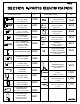
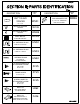
DESCRIPTION 8687 8686 FRAME HEAD 2 1/4" X 5" DEEP USE 8685 STOP 8633 8634 INT. HORIZONTAL 2 1/4" X 5" DEEP USE 8685 STOP 8633 8664 INT. HORIZONTAL 2 1/4" X 3 1/2" DEEP USE #8665 GLASS STOP 8666 8667 INT. HORIZONTAL 4" X 3 1/2" DEEP USE #8668 GLASS STOP 8554 8634 INT. HORIZONTAL for BUTT GLAZE APPS. 2 1/4" X 5" DEEP PART NO.
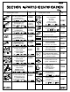
DESCRIPTION FS98 FS98 FS08 FS09 SHEAR BLOCK PKG. for 1G67 & 2G23 HORIZ. to VERTICALS PART NO. DESCRIPTION TRANSOM HEADER CLIP PACKAGE for 1G58 K368 (HEAD & SILL RUN THRU) SHEAR BLOCK PKG. for 1G59 SILL at VERT. INTER. THRU INCLUDES(1)FT51 & (1) FT52 & (8) STT6 SCREWS K319 HN13 SHEAR BLOCK PKG. for 1G72 HORIZ. to VERTICALS SETTING CHAIR PKG. for 1G73 HORIZ. K198 SETTING CHAIR PKG.
DESCRIPTION BUTT GLAZE SPACER 1/2" x 1/4" PART NO.
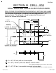
PAGE #6 SECTION III - DRILL JIGS DRILL JIG #H262 CAN ALSO BE PURCHASED DRILL FIXTURE FOR INTERMEDIATE HORIZONTALS, VERTICALS AND JAMBS The drill guide shown below is designed to be field prepared from 1" x 3" aluminum angle. The drill guide is used by aligning off the back and ends of the member being prepared. 3.000 #7 DRILL .201 dia. (8) 2.250 2.000 #21 DRILL .159" dia. (4) 1.250 .625 .178 LOCATE JIG EDGE AT END OF HORIZONTAL A A .375 C B .431 C B LOCATE JIG AT BACK OF MULLION 2.
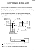
PAGE #7 SECTION III - DRILL JIGS DRILL JIG #DJ06 FOR INTERMEDIATE HORIZONTALS #1G72 AND #1G73 The drill guide is used by aligning off the back and ends of the members being prepared for shear blocks. For the left side vertical members, drill from this side as shown below. For the right side vertical members, turn the drill jig over and drill from the opposite side. .159 DIA. B 1G73 1.000 1G72 .500 B HORIZONTAL END PREP (#21 DRILL) .438 .900 1.
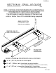
PAGE #8 SECTION III - DRILL JIG GUIDE CONT. JAMB LOCATION LOCATE DRILL JIG AT END OF SILL AND HEAD. SCREW SPLINE APPLICATION DRILL FIXTURE FOR INTERMEDIATE HORIZONTALS, INTERMEDIATE VERTICALS AND JAMBS The drill guide is used by aligning off the back and ends or center lines of the member being prepared. CENTER LINE OF VERTICAL MULLION /8 23 CL " N, R W HO MILA S L SI SIL AD HE /8" 3 2 Detail #1 REFER TO PAGE #6 FOR SPECIFIC HOLE LOCATIONS. = A = #7 (.201 dia.
PAGE #9 SECTION III - DRILL JIG GUIDE CONT. LEFT JAMB SHOWN, RIGHT JAMB AND INTERMEDIATE VERTICALS ARE PREPPED SIMILAR. 1G59 H262 DRILL JIG SHEAR BLOCK APPLICATION CENTER LINE OF HORIZONTAL INTERMEDIATE CL REFER TO PAGE #6 FOR SPECIFIC HOLE LOCATIONS ON THE DRILL JIG.
PAGE #10 SECTION III - DRILL JIG GUIDE CONT. DRILL JIG #DJ06 FOR INTERMEDIATE HORIZONTALS #1G72 AND #1G73 INTERMEDIATE HORIZONTAL TO SHEAR BLOCK ATTACHMENT This drill guide is used by aligning off the ends of the horizontal intermediate member being prepared. See Detail #3 below. C C DJ06 DRILL JIG C C 72 1G DJ06 DRILL JIG Detail #3 73 1G = C = #7 (.201 dia.
PAGE #11 SECTION III - DRILL JIG GUIDE CONT. 1G59 LEFT JAMB SHOWN, RIGHT JAMB AND INTERMEDIATE VERTICALS ARE PREPPED SIMILAR. DJ06 DRILL JIG TOP OF HORIZONTAL INTERMEDIATE FOR 1G72 (B) REFER TO PAGE #7 FOR SPECIFIC HOLE FOR 1G73 (B) LOCATIONS ON THE DRILL JIG. K198 SHEAR BLOCK SHOWN, K197 IS SIMILAR. Detail #4 = B = #21 (.159 dia.) drill shear block to vertical mullion.
PAGE #12 SECTION IV - FABRICATION HEAD AND SILL FABRICATION AND PREPARATION STEP #1 The series 955 Tech Set system is designed to be fabricated with the head and sill running through. The jambs and vertical mullions will meet at the top of the sill and at the snap location of the removable stop at the head. Cut the head and sill members to the rough opening measurement minus (-) the vertical caulk joints. This dimension could be 1/4" through 3/4" depending upon the condition. See Elevation #1 below.
APPLY A CONTINUOUS BEAD OF SEALANT AND TOOL INTO THE THERMAL STRUT RACE. 1/4" dia. WEEP APPLY A SMALL AMOUNT OF SILICONE SEALANT TO BOTH SIDES OF THE WEEP HOLE LOCATION. USE ONE BLOCK PER WEEP HOLE, AS REQUIRED.
PAGE #14 SECTION IV - FABRICATION CONT. INTERMEDIATE HORIZONTAL FABRICATION AND PREPARATION STEP #7 Cut the intermediate horizontals to D.L.O. width. Cut the glass stops for the intermediate horizontals and head member to D.L.O. minus (-) 1/32" for ease of installation. STEP #8 Prep the ends of the intermediate horizontals for the horizontal to shear block prep. See detail #9 below. See page #6 for the drill guide required to correctly identify the holes required for the shear block attachment.
PAGE #15 SECTION IV - FABRICATION (CONT.) INTERMEDIATE HORIZONTAL FACE STEP #9 Cut horizontal face member (#8553) to span 3 lites (or a maximum of 15’-0"). Allow 1/4" at splice joints for expansion. Splice ONLY at center lines of vertical mullions. See Detail #10 below. D.L.O. INTERIOR 1G59 2 3/8" D.L.O. 2 3/8" 8663 K461 BRIDGE REQUIRED 8663 D.L.O. 2 3/8" D.L.O. 8663 1/4" HORIZONTAL FACE LENGTH (15 ft. max.
PAGE #16 SECTION IV - FABRICATION (CONT.) INTERMEDIATE HORIZONTAL FACE STEP #11 15/16" Drill 1/4" diameter weep holes in the horizontal face member at 48" on center or 2 per D.L.O. at quarter points. Install weep baffles over the holes with silicone. Do not plug the weep holes with silicone. See Detail #12 below. WNB9 48" O.C. CL 1/4" DIA. WEEP HOLES 8553 FACE WNB9 APPLY BAFFLES WITH A SMALL AMOUNT OF SILICONE TYPE SEALANT.
PAGE #17 SECTION IV - FABRICATION (CONT.) INTERMEDIATE HORIZONTAL FACE JAMB AND VERTICAL MULLION FABRICATION AND PREPARATION STEP #13 If the project is being built as head and sill thru, the vertical members will be cut to D.L.O. plus (+) 1 3/16". STEP #14 The vertical members must also be coped to fit into the head. See details #13 and #14 below. 1G59 JAMB Detail #13 1G61 VERTICAL MULLION 1.187 Detail #14 TO HEAD 1.
PAGE #18 SECTION IV - FABRICATION CONT. STEP #16 If horizontal intermediates are being incorporated, the verticals must be prepped for the horizontal shear block attachment. See detail #15 below to determine the horizontal location. Refer to pages #6 through #11 for the drill jigs and the drill jig guides to correctly identify the required holes to drill for the particular horizontal / shear block being used. TO HEAD 1.187 1.187 LL .431 DRI 21) # ( . ALL DIA .159 U (1) W S) THR LACE (2 P 2.250 REF.
PAGE #19 SECTION IV - FABRICATION HORIZONTAL INTERMEDIATE SHEAR BLOCK FABRICATION CONT. {K368 FABRICATED PACKAGE} STEP #17 The intermediate horizontal shear blocks are to be prepped from #EX43. One (1) #EX43 is required at each end of the intermediate horizontal. See detail #16 below for preparation. 2.750 1.000 .968 .350 EX43 #7 DRILL (.201) THRU CLEAR HOLE FOR #10 SCREW #STL1 - TYP. CL # 25 DRILL (.1495) THRU 2 WALLS PILOT HOLE FOR #10 SCREW #MRF5 - TYP. Detail #16 1.375 .360 .
PAGE #20 SECTION IV - FABRICATION HEAD ANCHOR FABRICATION STEP #19 CONT. {FS97 - FABRICATED PART} Cut and fabricate the head anchors from #8695 as shown in detail #18 below. 1.000" .500" FS97 5/16" x 13/16" SLOT 1.500" Detail #18 3.000" 1/2 SIZE SETTING BLOCK FABRICATION K196 FOR 1G73 FABRICATED PACKAGE IS AVAILABLE. STEP #20 Cut and fabricate the setting blocks from #1918 extrusions. Two (2) setting blocks are required per daylight opening. See detail #19 below for fabrication.
PAGE #21 SECTION IV - FABRICATION CONT. 1/4" GLAZING ADAPTOR FABRICATION AND PREPARATION STEP #22 Cut the #8651 glazing adaptor to daylight opening minus 1/16" for verticals and horizontals. See detail #20 below. STEP #23 Notch the #8651 horizontal glazing adaptors to clear the vertical adaptors as shown in detail #21 below. Prep the glazing adaptors for the attachment screws as shown below. Butt the horizontal adaptor to the vertical and fasten with SFZ5 screws as shown.
1G67 SHOWN, SEALANT APPLICATION TYPICAL AT ALL HORIZONTALS. 1G67 Apply silicone sealant to the ends of the intermediate horizontals Apply a continuous bead of silicone and tool into the thermal strut race. Detail #22 2G23 Apply a continuous bead of silicone and tool into the thermal strut race.
PAGE #23 SECTION V - ASSEMBLY CONT. FRAME PREASSEMBLY with standard verticals and horizontals. STEP #26 Attach the intermediate horizontal shear blocks to the vertical mullions and jambs. See detail #24 below. STEP #27 Attach the intermediate horizontals to the vertical mullions and jambs. See detail #24 below.
PAGE #24 SECTION V - ASSEMBLY CONT. STEP #28 Butter the top ends of the jambs and vertical mullions. Then attach the head to the verticals with #STV3 screws. It will be necessary to coat the screws with wax before installation to prevent stripping. See details #25 and #26 below. STEP #29 Butter the bottom ends of the jambs and vertical mullions. Then attach the sill to the verticals with #STV3 screws. It will be necessary to coat the screws with wax before installation to prevent stripping.
PAGE #25 SECTION V - ASSEMBLY CONT. FRAME PREASSEMBLY with butt glazed vertical intermediates and roll on face horizontals. STEP #31 Attach the intermediate horizontal shear blocks to the vertical mullions and jambs. See detail #28 below. STEP #32 Attach the intermediate horizontals to the vertical mullions and jambs. See detail #28 below.
PAGE #26 SECTION V - ASSEMBLY CONT. STEP #33 Butter the top ends of the jambs and vertical butt glaze mullions. Then attach the head to the verticals with #STV3 screws. It will be necessary to coat the screws with wax before installation to prevent stripping. See details #29 and #30 below. STEP #34 Butter the bottom ends of the jambs and vertical butt glaze mullions. Then attach the sill to the verticals with #STV3 screws.
PAGE #27 SECTION VI - FRAME INSTALLATION CONT. HORIZONTAL SILL ANCHOR INSTALLATION STEP #36 At both ends of the rough opening, mark where the face of the frame is intended to be located. Snap a chalk line from both marks. From this dimension, snap another line 3 1/8" back toward the interior of the opening. This will be the center line of the sill anchor prep. See detail #32 below. STEP #37 Mark the center lines of the frame mullions on the rough opening.
PAGE #28 SECTION VI - FRAME INSTALLATION CONT. HEAD ANCHOR AND VERTICAL SILL ANCHOR INSTALLATION {FS97 & FT01 - FABRICATED PARTS} STEP #38 Mark the center lines of the frame mullions on the rough opening. Measure over from the mullion and jamb centers 6" and 16" O.C. The vertical sill anchors, FT01, will be installed prior to setting the assembled frame, as shown in Detail #35 below. The silde in head anchors, FS97, are installed into the assembled frame head, 2 per D.L.O.
PAGE #29 SECTION VI - FRAME INSTALLATION CONT. FRAME INSTALLATION INTO THE OPENING {FS97, FT01 & FS99 - FABRICATED PARTS} STEP #39 Slide the FS97 head anchor into the head as shown in Detail #36 below. SLIDE THE HEAD ANCHOR INTO THE HEAD MEMBER 6" OFF EACH MULLION AND 16" ON CENTER. Detail #36 FS97 C. O. . " 16 AX M OM LS FR A 6" RTIC VE M ROCALS F 6" RTI VE INTERIOR FS99 Detail #37 Detail #38 STEP #40 FT01 The 955 system is designed to rotate into the opening from the interior of the building.
PAGE #30 SECTION VI - FRAME INSTALLATION CONT. BACKER ROD / EXTERIOR SEAL AND EXTERIOR GASKET STEP #41 Install a continuous row of backer rod at the exterior side of the frame and seal with silicone sealant. See the various details below. STEP #42 If the exterior glazing preset gasket (WNB9) has not been installed at this time, do so now. Be sure to add 2% of the cut length to the gasket to prevent gaps at the gasket ends due to gasket shrinkage. CUT LENGTH FORMULA FOR WNB9 = D.L.O.
HN07 SETTING BLOCK SEAL HN92 IN PLACE 1 PO /4 INT 1 PO /4 INT HN3 1 PO /4 INT 1 PO /4 INT CSJ 10/2007
PAGE #32 SECTION VII - GLASS INSTALLATION CONT. 1G61 STEP #46 HWD1 WATER DEFLECTOR AT VERTICAL INTERMEDIATE, LEFT JAMB, AND RIGHT JAMB Remove the paper backing and position the water deflector as shown in this figure. It will be necessary to set the water deflector in a small amount of sealant, to ensure that it stays in place when setting the lower glass unit. Detail # 44 1G67 STD. 1G72, 1G73, & 2G23 OPT. TYP.
PAGE #33 SECTION VII - GLASS INSTALLATION USING BUTT GLAZED MULLIONS CONT. STEP #47 The horizontal bridge is intended to prevent any water in the glazing pocket from running down the butt glazed vertical intermediate at the horizontal connection. Correct sealing is important in this step. Apply a bead of sealant around the opening of the left and right horizontals and across the vertical butt glaze mullion. This is to set the bridge assembly into. See detail #47 below.
PAGE #34 SECTION VII - GLASS INSTALLATION USING BUTT GLAZED MULLIONS CONT. BUTT GLAZE MULLION 8663 HORIZONTAL 2G23 K461 STEP #48 AFTER THE BRIDGE IS SET IN PLACE, SEAL AROUND BRIDGE PERIMETER WITH A NONHARDENING BUTYL TYPE SEALANT.
PAGE #35 SECTION VII - GLASS INSTALLATION USING BUTT GLAZED MULLIONS CONT. STEP #49 Follow the glass setting procedure as shown in Detail #50 below and Detail #51 on page #36. 8663 BUTT GLAZED MULLION 8663 BUTT GLAZED MULLION 1G68 JAMB INSTALL THIS UNIT - 2nd TO LAST - INSTALL THIS UNIT - LAST EXTERIOR GLAZING GASKET WNB9 INSTALLED Detail #49 STEP #50 Position the glass units as shown in Detail #50 below maintain the appropriate glass bite per mullion.
PAGE #36 SECTION VII - GLASS INSTALLATION USING BUTT GLAZED MULLIONS STEP #51 CONT. K368 Detail #51 K368 Install the butt glazing spacer (WSA1) between the butt glaze mullion and the glass unit. This gap should be small enough to provide tension on the spacer to hold it in place. The space will bottom out against the locator on the mullion. 8663 WSA1 WSA1 1/2" GAP NOTE: Any type of temporary glazing retainer will have to be field fabricated and installed by the contractor.
PAGE #37 SECTION VII - GLASS INSTALLATION USING BUTT GLAZED MULLIONS CONT. STEP #53 After the interior structural joint has cured overnight the exterior joint seal can then be applied. Use backer rod to fill the cavity to 2/3 full leaving enough void to seal the exterior glass panes together. See Detail # 53 below. A clean professional application of the structural silicone is required here.
PAGE #38 SECTION VII - GLASS INSTALLATION CONT. HORIZONTAL GLASS SIZE FORMULA (D.L.O. + 1.000") VERTICAL GLASS SIZE FORMULA (D.L.O. + 1" or D.L.O. + 7/8") STEP #54 8685 GLZ. STOP 7/16" TYP. D.L.O. 8685 GLZ. STOP 7/16" TYP. GLASS SIZE = D.L.O. + 7/8" D.L.O. Detail #54 1/2" TYP. GLASS SIZE = D.L.O. + 1" 8685 GLZ. STOP D.L.O. GLASS SIZE = D.L.O. + 7/8" 1/2" TYP. 7/16" TYP. The glass size formulas for the 955 system are based on D.L.O. plus 1", horizontally and D.L.O.
PAGE #39 SECTION VII - GLASS INSTALLATION CONT. ANTIWALK BLOCK INSTALLATION STEP #56 Choose the appropriate antiwalk block for the required glass type. Use block #HN50 at 1/4" glass and #HN53 at 1" glass. Compress the antiwalk and insert into the deep pocket at midpoint. See the details below.
PAGE #40 SECTION VIII - DOOR FRAME INSTALLATION NOTE: If an entrance frame is required, it must be installed first. See the parts description pages for the appropriate door jamb and transom bar for the system being used. STEP 1) Correctly locate the entrance frame in the opening. STEP 2) Apply a bead of sealant around the interior portion of the jamb to set the member into, and tie the side lite sealant or condition sealant into the bead of sealant to be applied under the threshold.
PAGE #41 SECTION VIII - DOOR FRAME INSTALLATION CONT. C.O.C. APPLICATION 5/8" 1/4" Dia. Weep at 1/4 Points 8580 K450 RJ K451 LJ At condition attach through the header with flat head screws, located 6" from the ends and 24" on center, maximum spacing. W138 Detail # 60 K452 8581 8580 K450 RJ K451 LJ W138 Detail # 61 SURFACE CLOSER APPLICATION 9154/9155 W138 1/4" Dia. Weep at 1/4 Points Detail # 62 1.
PAGE #42 SECTION VIII - DOOR FRAME INSTALLATION CONT. TRANSOM JAMB APPLIED GLAZING 8578 8581 8578 DRILL & CNTR. SINK for SFZ5 #8-15 X 3/8 PL-FH-SMS 18-8 AB UC 4" FROM ENDS & 16" ON CENTER W105 BEAD OF SEALANT WNB9 8579 8579 BEAD OF SEALANT Detail # 67 1.000 VERTICAL CUT LENGTH FORMULA = D.L.O.
PAGE #43 SECTION VI A - DOOR FRAME INSTALLATION CONT. TRANSOM HEADER AND APPLIED TRANSOM GLAZING K462 CLIP ATTACHED WITH STT6 SCREWS 1G58 HEAD 1G58 TRANSOM HEADER SEALANT 8579 TRANSOM GLAZING STOP SET IN A BEAD OF SEALANT VERTICALLY 8581 DOOR JAMB Detail # 69 Locate the header clip onto the end of the header, fasten the clip to the header with the screws provided in the clip package. Apply sealant to the ends of the header and install with the screws provided.