Series 5500 interior glazed curtain wall Installation Instructions Part NO.
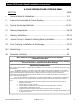
Series 5500 Inside Glazed Installation Instructions S-5500 SCREW SPLINE CURTAIN WALL SECTION PAGE I. General Notes & Guidelines………………………………………..…………. 3-4 II. Frame Unit Assembly & Frame Sealing………………………...…………. 5-14 III. Typical Anchorage Methods ………………………………………...…..……15-23 IV. Glazing Preparation……………………………………………………...………..24-29 V. Glazing Installation……………………………………………………………..… 30-31 VI. Interior Drive-In Gasket & Glazing Bead Installation……………...….32-36 VII.
Series 5500 Inside Glazed Installation Instructions Section I: General Notes and Guidelines I. II. HANDLING / STORING / PROTECTING ALUMINUM - The following precautions are recommended to assure early acceptance of your products and workmanship. A. HANDLE CAREFULLY - Store with adequate separation between components so the material will not rub together. Store the material off the ground. Protect materials against weather elements and other construction trades. B.
Series 5500 Inside Glazed Installation Instructions SECTION I: GENERAL NOTES and GUIDELINES F. Follow EFCO framing installation and glazing instructions. G. Verify contents of all material shipments received upon their arrival. Verify quantity and correct finishes. NOTIFY EFCO IMMEDIATELY OF ANY DISCREPANCIES OR DAMAGE THAT MAY HAVE OCCURRED. H. Throughout these instructions the term “SEALANT” will appear.
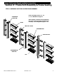
Series 5500 Inside Glazed Installation Instructions Section II: Frame Unit Assembly & Frame Sealing STEP #1 ASSEMBLE OUTSIDE GLAZED FRAME MEMBERS Frame assembly screws 1/4” –14 x 1 1/2” HWSMS 18-8 Typical PERIMETER MULLION Note: Sealant or Gasket must be applied to the ends of each horizontal member before assembly. (See enlargement pages 6 –10 HEAD VERTICAL FILLER INTERMEDIATE MULLION CLIP INTERMEDIATE VERTICAL SILL EFCO CORPORATION 6/2012 PART NO.
Series 5500 Inside Glazed Installation Instructions Section II: Frame Unit Assembly & Frame Sealing STEP #2 SEAL EXTERIOR PRESSURE COVER A. Plug the ends of the exterior portion of the I.G. horizontals with backer rod. Recess the backer rod at least 1/4” from each end of the pressure cover. B. Apply a generous amount of sealant to cover the hollow portion of the cover as shown below, on each end. Apply sealant to each end of the horizontal as shown on page 7.
Series 5500 Inside Glazed Installation Instructions Section II: Frame Unit Assembly & Frame Sealing Apply a generous bead of sealant to the ends of the horizontal mullion to a minimum of 1” back from the face of the horizontal glazing pocket. HEAD & INTERMEDIATE I.G. HORIZONTAL After each frame unit assembly is complete, wipe off all excess sealant, and allow the frame unit to cure. EFCO CORPORATION 6/2012 PART NO.
Series 5500 Inside Glazed Installation Instructions Section II: Frame Unit Assembly & Frame Sealing Note: Tool the sealant smooth on each end of the covers. After the sealant partially cures, use a blade to cut the excess sealant flush with the surfaces of the covers. EFCO CORPORATION 6/2012 PART NO.
Series 5500 Inside Glazed Installation Instructions Section II: Frame Unit Assembly & Frame Sealing Apply a generous bead of sealant to the ends of the horizontal mullion to a minimum of 1” back from the face of the horizontal glazing pocket. After each frame unit assembly is complete, wipe off all excess sealant and allow the frame unit to cure. OR Optional Gasket seal H10Z . Install gasket to each end of horizontal before attaching to vertical SILL EFCO CORPORATION 6/2012 PART NO.
Series 5500 Inside Glazed Installation Instructions Section II: Frame Unit Assembly & Frame Sealing STEP #3 APPLY SILL PRESSURE COVERS Apply a bed of sealant to the side of the vertical cover adjacent to where the ends of the sill pressure covers will be after installation. The sealant bed should be approximately 2 1/4” high x 1/16” thick and the depth of the vertical cover. Align the sealant bed with the sill.
Series 5500 Inside Glazed Installation Instructions Section II: Frame Unit Assembly & Frame Sealing STEP #4 APPLY SILL PRESSURE COVERS A. Plug the ends of the sill pressure covers with backer rod. Recess the backer rod at least 1/4” from each end and apply a generous amount of sealant to cover the ends of the covers. B. Tool the sealant smooth, but allow it to slightly extend past the ends of the cover as shown. Apply backer rods in each end of cover. Apply sealant on each end of cover.
Series 5500 Inside Glazed Installation Instructions Section II: Frame Unit Assembly & Frame Sealing STEP #4 APPLY SILL PRESSURE COVERS A. Run a continuous bead of sealant in the reglet of the sill horizontal immediately before applying the exterior sill pressure cover as shown below. Do not block the weeps with sealant. (See inset below.) B. Slide on and rotate the sill pressure covers as shown to engage the horizontal cam. The sill horizontal has a continuous snap engagement to retain the cover.
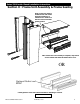
Series 5500 Inside Glazed Installation Instructions Section II: Frame Unit Assembly & Frame Sealing STEP #6 INSTALL FRAME COMPONENTS A. Snap-in PVC pocket fillers into the perimeter framing members. B. Plug the ends of the exterior portion of the vertical mullions with backer rod. Recess the backer rod at least 1/4” from each end and apply a generous amount of sealant to cover the ends of the mullions. Tool the sealant flush with the end of the mullion.
Series 5500 Inside Glazed Installation Instructions Section II: Frame Unit Assembly & Frame Sealing PERIMETER PVC POCKET FILLERS Apply backer rod and seal the ends of the mullions as shown including the glazing reglets. (At the top and bottom of mullions.) HEAD JAMB INTERMEDIATE VERTICAL EFCO CORPORATION 6/2012 PART NO.
Series 5500 Inside Glazed Installation Instructions Section III: Typical Anchorage Methods STEP #1 INSTALL FRAME COMPONENTS Refer to the approved shop drawings for job specific conditions, anchor type, anchor bolt sizes, and locations. Install assemblies according to approved shop drawings. The anchor type used must be selected based on the structural requirements and the substrate.
Series 5500 Inside Glazed Installation Instructions Section III: Typical Anchorage Methods STEP #2 INSTALL FRAME COMPONENTS A. Set the first frame into the opening using dead load shims to level the frame, and make all necessary adjustments to properly locate the frame to established benchmarks. B. After the frame is plumb and all adjustments have been made, match drill through the holes in the head and sill into the surrounding substrate, and apply the anchor bolts.
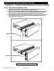
Series 5500 Inside Glazed Installation Instructions Section III: Typical Anchorage Methods ANCHOR BOLTS WITH SLEEVES AS REQ’D. INTERIOR VIEW STANDARD HEAD ANCHORAGE ANCHOR BOLTS AS REQ’D. Apply dead load shims at anchors and below verticals. INTERIOR VIEW STANDARD SILL ANCHORAGE EFCO CORPORATION 6/2012 PART NO.
Series 5500 Inside Glazed Installation Instructions Section III: Typical Anchorage Methods STEP #3 INSTALL FRAME COMPONENTS A. Repeating step 2, page 16, set each successive frame into the opening, snapping the verticals and fillers at each frame, until all frames are installed up to the last frame at the opposite jamb. B. Check frequently to ensure the installed framing is in the proper position with regard to established benchmarks. C. After securing the anchor bolts, snap-in head and sill fillers.
Series 5500 Inside Glazed Installation Instructions Section III: Typical Anchorage Methods STEP #4 SPECIAL SEALANT NOTE A. Seal the vertical fillers at the intersection of the heads, sills, and intermediate horizontals immediately before snapping the filler and the vertical mullions together. B. Tool the sealant smooth with the face of the glazing pocket and remove excess sealant from the glazing reglets.
Series 5500 Inside Glazed Installation Instructions Section III: Typical Anchorage Methods STEP #5 INSTALL FRAME COMPONENTS A. Set the last frame in the run into the opening mating the filler with the intermediate vertical until the filler and vertical snap together. B. When the frame is set level and plumb, apply the dead load shims below the verticals, and apply anchors as shown on page 16 step 2 (B). C. Snap-in head and sill fillers. D.
Series 5500 Inside Glazed Installation Instructions Section III: Typical Anchorage Methods STEP #6 INSTALL FRAME COMPONENTS – WELDED DEAD LOAD ANCHORS For installations with multi-spans, set the frame into the opening as instructed in previous steps, and apply the dead load anchors to the jambs with temporary screws at the proper location at the floor slab. Refer to the approved shop drawings for more information.
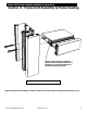
Series 5500 Inside Glazed Installation Instructions Section III: Typical Anchorage Methods NOTE: When welding, protect installed metal and glass from weld splatter. BUILDING STRUCTURE Weld to building structure per approved shop drawings. STEEL ANCHOR PER SHOP DRAWINGS NOTE: The elevation of the structure must be within the adjustment limits of the anchoring system. See approved shop drawings for limitations. WELDED DEAD LOAD ANCHORS EFCO CORPORATION 6/2012 PART NO.
Series 5500 Inside Glazed Installation Instructions Section III: Typical Anchorage Methods STEP #7 INSTALL FRAME COMPONENTS – WELDED WIND LOAD ANCHORS For installations with multi-spans, follow applicable notes from step 6. Match drill the mullion through the CENTER of the set of slots in the anchor. NOTE: The holes must be a minimum of 1” from the back of the mullion in order to clear any steel reinforcement located inside the system, as may be required on a job specific basis.
Series 5500 Inside Glazed Installation Instructions Section IV: Glazing Preparation STEP #1 PREPARE FRAME FOR JOINT PLUGS A. Fill the gasket and adapter raceways with sealant to close off the void at the joint plug locations. The sealant height should be a minimum of 1” long. B. Seal all connecting surfaces of the horizontal and vertical mullions with sealant for the attachment of the mullion joint plugs. Tool sealant into the joints at the thermal strut. Fill gasket and adapter raceways with sealant.
Series 5500 Inside Glazed Installation Instructions Section IV: Glazing Preparation STEP #2 INSTALL JOINT PLUGS A. Apply sealant to the contact surfaces of the joint plug as shown. B. Install the mullion joint plugs at the horizontal to vertical intersections as indicated. C. Tool the sealant that was pre-applied to the mullion in step 1, over the joint plugs and into the joints. MULLION JOINT PLUGS JOINT PLUGS – INTERMEDIATE SHOWN, HEAD AND SILL SIMILAR EFCO CORPORATION 6/2012 PART NO.
Series 5500 Inside Glazed Installation Instructions Section IV: Glazing Preparation STEP #3 TOOLING JOINT PLUGS A. After installation of the joint plugs, reseal the joint connecting the surfaces of the horizontal and vertical mullions with sealant over the joint plug as shown below. B. Provide a downward slope with the sealant, without interfering with the edge of the glass once the glass is set, to allow for drainage of water.
Series 5500 Inside Glazed Installation Instructions Section IV: Glazing Preparation STEP #4 INSTALL EXTERIOR GASKETS IN PRESSURE PLATE A. Remove the glazing gaskets from the reel, and allow them to relax and shrink. B. Apply sealant into the raceways a minimum of 2” in each direction from the corners of the D.L.O. (Refer to the illustration below.) C. Once the gaskets have relaxed, cut them and install the gaskets into position. The interior vertical gaskets must be cut vertical D.L.O. plus 1 3/4”.
Series 5500 Inside Glazed Installation Instructions Section IV: Glazing Preparation STEP #5 INSTALL EXTERIOR GASKETS IN PRESSURE PLATE Important Note: The glazing must be set immediately after this step before the sealant begins to cure. If the sealant hardens before the glazing has been set, proper gasket compression at the corners will be impeded and may result in leakage. Sections of mullions broken out for clarity.
Series 5500 Inside Glazed Installation Instructions Section V: Glazing Installation IMPORTANT NOTE: EFCO recommends using conventional tubular spacers only for insulated glass units with the S-5500. This is due to the possible collapse of the spacer when used with drive-in wedge glazing gaskets. STEP #1 INSTALL GLAZING MATERIALS A. Using suction cups, gently insert a glass edge (or other glazing infill) into the deep pocket of the vertical mullion. B.
Series 5500 Inside Glazed Installation Instructions Section V: Glazing Installation STEP #3 INSTALL ANTI-WALK BLOCKS A. Stretch the anti-walk blocks until they are elongated enough to fit between the glass face and the front face of the glazing pocket. B. Install and position anti-walk blocks in the verticals at the center of each D.L.O.
Series 5500 Inside Glazed Installation Instructions Section VI: Interior Drive-In Gasket & Glazing Bead Installation STEP #1 INSTALL DRIVE-IN GASKETS IN VERTICAL MULLIONS A. Remove the exterior drive-in wedge gasket material from the reel, and allow the gasket to relax and shrink. B. Remove any temporary retainer gaskets previously applied, from the opening at hand. C. The exterior vertical gaskets must be cut vertical D.L.O. plus 1 3/4”.
Series 5500 Inside Glazed Installation Instructions Section VI: Interior Drive-In Gasket & Glazing Bead Installation STEP #2 SEAL AND INSTALL GLAZING BEAD A. Apply sealant to the ends of the glazing bead. (See inset.) B. Apply sealant to the side of the vertical mullion below the horizontal, where the bead will contact when set in place. C. Install the bead as shown in the illustration below. Apply sealant to the side of the mullion. NOTE: The typical glass bite for the I.G.
Series 5500 Inside Glazed Installation Instructions Section VI: Interior Drive-In Gasket & Glazing Bead Installation STEP #3 SEAL GLAZING BEAD AND APPLY HORIZONTAL DRIVE-IN GASKETS Tool the sealant smooth and watertight on each end of the glazing beads. Apply sealant to the vertical gaskets where they will contact the horizontal gaskets on each end, behind the glazing bead or glazing pocket, as shown below. Cut the horizontal gaskets D.L.O.
Series 5500 Inside Glazed Installation Instructions Section VI: Interior Drive-In Gasket & Glazing Bead Installation Seal all gasket corners by pulling the horizontal gasket back, sealing the ends, and pressing the gasket back into the vertical gasket. Apply sealant to vertical gaskets. INTERIOR VIEW EFCO CORPORATION 6/2012 PART NO.
Series 5500 Inside Glazed Installation Instructions Section VI: Interior Drive-In Gasket & Glazing Bead Installation STEP #4 APPLY INTERIOR GLAZING BEAD COVER Snap the interior glazing bead covers onto the inside glazed horizontals. Remove any excess sealant that remains. Note: The interior bead cover should be applied before the sealant at the ends of the glazing bead begins to harden. If not, the sealant may need to be removed where the cover slips onto the glazing bead.
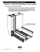
Series 5500 Inside Glazed Installation Instructions Section VII: Door Framing Installation & Anchorage STEP #1 INSTALL ADJACENT FRAME The following example depicts a typical S-5500 elevation with door framing. The following illustrations show the anchoring of the frame assemblies utilizing the standard method for anchoring of the S-5500.
Series 5500 Inside Glazed Installation Instructions Section VII: Door Framing Installation & Anchorage ANCHORED AS REQUIRED DOOR JAMB ANCHORED AS REQUIRED EFCO CORPORATION 6/2012 PART NO.
Series 5500 Inside Glazed Installation Instructions STEP #2 ANCHOR FIRST DOOR JAMB The frame directly adjacent to the door opening will have the first door jamb. This jamb is 3/4” longer than the typical mullions and extends below the sill down to the top of the floor slab. To maintain Exterior sealant line, apply silicone to the interior surfaces of the door jamb and tool to the condition.
Series 5500 Inside Glazed Installation Instructions Section VII: Door Framing Installation & Anchorage DOOR JAMB ANCHOR BOLTS AS REQUIRED EFCO CORPORATION 6/2012 ANCHOR CLIP PART NO.
Series 5500 Inside Glazed Installation Instructions Section VII: Door Framing Installation & Anchorage STEP #3 SET DOOR FRAME A. Carefully position the door frame into opening. Extreme care should be taken to protect the filler part of the frame during shipment and handling. Damage to the edges of the filler will be noticeable after it is snapped into the door jamb. B. Using blocks of wood and ‘C’ clamps, carefully snap the filler into the door jamb working from one end to the other.
Series 5500 Inside Glazed Installation Instructions Section VII: Door Framing Installation & Anchorage STEP #4 ANCHOR DOOR FRAME A. After the frame is set level and plumb, anchor the head of the elevation as required. Refer to previous sections for more information. DOOR JAMB ANCHOR CLIP EFCO CORPORATION 6/2012 PART NO.
Series 5500 Inside Glazed Installation Instructions STEP #5 ANCHOR DOOR JAMB A. To maintain Exterior sealant line, apply silicone to the interior surfaces of the door jamb and tool to the condition. B. Ensure the clip is flush with the bottom of the mullion and the top of the condition. Attach the anchor clip to the door jamb with screws as shown. C. Drill anchor bolt holes through the clip and into the substrate as required. D. Bolt the anchor clip to the condition. (See page 39.
Series 5500 Inside Glazed Installation Instructions Section VII: Door Framing Installation & Anchorage STEP #6 INSTALL REMAINING FRAMES AND GLAZE CURTAIN WALL A. Set and install the remaining frames as required and instructed in previous sections. B. Prepare and glaze the elevation as shown in Section IV, Section V, and Section Vi EFCO CORPORATION 6/2012 PART NO.
Series 5500 Inside Glazed Installation Instructions Section VII: Door Framing Installation & Anchorage STEP #7 INSTALL VERTICAL SUBFRAMES A. Apply sealant into the glazing gasket reglets of the exterior covers of the door jambs and door header as shown. B. The vertical subframes are cut to run from the condition at the sill through to the bottom of the door header with the head subframe running in between. Apply sealant to each end of the subframe.
Series 5500 Inside Glazed Installation Instructions Section VII: Door Framing Installation & Anchorage STEP #8 INSTALL DOOR HEAD SUBFRAME Unless a concealed overhead closer is used, a subframe will be required at the door head. See the detail below for the optional door header for concealed overhead closer applications. A. The subframe at the door head is cut to run between the vertical subframes. Apply sealant to each end of the subframe.
Series 5500 Inside Glazed Installation Instructions Section VII: Door Framing Installation & Anchorage STEP #9 INSTALL DOOR STOPS A. First, install the door stop at the head. This stop is cut the same length as the door head subframe. B. The vertical door stops are cut to run from the condition at the sill, to the bottom of the door head subframe. The tops of the stops are notched as shown in the drawing inset.
Series 5500 Inside Glazed Installation Instructions Section VIII: Reinforcing STEP #1 INSTALL STEEL REINFORCEMENT At large span or high wind load areas, steel reinforcement may be necessary. Reinforcement requirements will vary from project to project. Refer to the approved shop drawings for reinforcement requirements. A. Slide steel reinforcement in from the end of the mullion.
Series 5500 Inside Glazed Installation Instructions Section IX: Perimeter Caulking STEP #1 PREPARE JOINT FOR CAULK APPLICATION A. Perimeter caulk joint application should not begin until the curtain wall elevation has been completely erected and glazed. B. Clean and prime the perimeter caulk joint opening as recommended by the sealant manufacturer’s installation instructions. C. Use the appropriate sized backer rod for the desired caulk joint. The minimum caulk joint size for the S-5500 is 3/4”.