Series 5500 SSG and Captured corner mullion Installation Instructions Part NO.
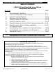
S-5500 SSG and Captured Corner Mullion Installation Instructions TABLE OF CONTENTS S-5500 SSG and Captured Corner Mullion Installation Instructions SECTION I. II. III. IV. V. VI. VII. VIII. IX. X. XI. PAGE General Notes & Guidelines …………………………………………. 3-4 Frame Unit Assembly & Frame Sealing …………………………… 5-11 Typical Anchorage Methods ………………………………………….. 12-20 Alternate Anchorage Method ………….…………………………..… 21-26 Glazing Preparation (Captured)……………….……………………… 27-34 Glazing Preparation (SSG)……………..…………………………….
S-5500 SSG and Captured Corner Mullion Installation Instructions Section I: General Notes I. II. HANDLING / STORING / PROTECTING ALUMINUM - The following precautions are recommended to assure early acceptance of your products and workmanship. A. HANDLE CAREFULLY - Store with adequate separation between components so the material will not rub together. Store the material off the ground. Protect materials against weather elements and other construction trades. B.
S-5500 SSG and Captured Corner Mullion Installation Instructions Section I: General Notes F. Follow EFCO framing installation and glazing instructions. G. Verify contents of all material shipments received upon their arrival. Verify quantities and correct finishes. NOTIFY EFCO IMMEDIATELY OF ANY DISCREPANCIES OR DAMAGE THAT MAY HAVE OCCURRED. H. Throughout these instructions the term “SEALANT” will appear.
S-5500 SSG and Captured Corner Mullion Installation Instructions Section II: Frame Unit Assembly & Frame Sealing Captured System STEP #1 ASSEMBLE FRAMING MEMBERS Apply sealant to the ends of the horizontals as shown. Mitered end of sill After each frame unit assembly is complete, wipe off all excess sealant and allow the frame unit to cure. Refer to “Section II: Frame Unit Assembly & Frame Sealing” of the Series 5500 Outside Glazed or Inside Glazed Installation Instructions for additional information.
S-5500 SSG and Captured Corner Mullion Installation Instructions Section II: Frame Unit Assembly & Frame Sealing Captured System Apply sealant to the ends of the horizontals as shown. Mitered end of intermediate horizontal After each frame unit assembly is complete, wipe off all excess sealant and allow the frame unit to cure. Refer to “Section II: Frame Unit Assembly & Frame Sealing” of the Series 5500 Outside Glazed or Inside Glazed Installation Instructions for additional information.
S-5500 SSG and Captured Corner Mullion Installation Instructions Section II: Frame Unit Assembly & Frame Sealing Captured System Apply sealant to the ends of the horizontals as shown. Mitered end of head After each frame unit assembly is complete, wipe off all excess sealant and allow the frame unit to cure. Refer to “Section II: Frame Unit Assembly & Frame Sealing” of the Series 5500 Outside Glazed or Inside Glazed Installation Instructions for additional information.
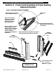
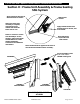
S-5500 SSG and Captured Corner Mullion Installation Instructions Section II: Frame Unit Assembly & Frame Sealing SSG System Mitered end of sill Apply sealant to the ends of the horizontals as shown. After each frame unit assembly is complete, wipe off all excess sealant and allow the frame unit to cure. Plug with backer rod, and fill void with sealant. Apply sealant between the thermal struts as shown, and tool smooth.
S-5500 SSG and Captured Corner Mullion Installation Instructions Section II: Frame Unit Assembly & Frame Sealing SSG System Apply sealant to the ends of the horizontals as shown. Mitered end of intermediate horizontal After each frame unit assembly is complete, wipe off all excess sealant and allow the frame unit to cure. Refer to “Section II: Frame Unit Assembly & Frame Sealing” of the Series 5500 Outside Glazed or Inside Glazed Installation Instructions for additional information.
S-5500 SSG and Captured Corner Mullion Installation Instructions Section II: Frame Unit Assembly & Frame Sealing SSG System Apply sealant to the ends of the horizontals as shown. Mitered end of head After each frame unit assembly is complete, wipe off all excess sealant and allow the frame unit to cure. Refer to “Section II: Frame Unit Assembly & Frame Sealing” of the Series 5500 Outside Glazed or Inside Glazed Installation Instructions for additional information.
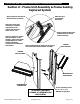
S-5500 SSG and Captured Corner Mullion Installation Instructions Section II: Frame Unit Assembly & Frame Sealing SSG System Under certain circumstances, it may be necessary to use drop-on heads and sills with mullion ‘M’ and ‘F’ anchors. Refer to alternate anchorage methods section for more information. Apply sealant to the ends of the horizontals as shown. After each frame unit assembly is complete, wipe off all excess sealant and allow the frame unit to cure.
S-5500 SSG and Captured Corner Mullion Installation Instructions Section III: Typical Anchorage Methods STEP #1 INSTALL FRAME COMPONENTS A. Refer to the approved shop drawings for job specific conditions, anchor type, anchor bolt sizes, and locations. Install assemblies according to approved shop drawings. The anchor type used must be selected based on the structural requirements and the substrate. B.
S-5500 SSG and Captured Corner Mullion Installation Instructions Section III: Typical Anchorage Methods STEP #2 INSTALL FRAME COMPONENTS A. After the first corner frame is set into the opening plumb and in the proper position with regard to established benchmarks, anchor the frame at the head, sill and intermediate floor slab if required. B. Stack the next corner frame into the opening, and mate the corner mullions together as shown in the illustration below. C.
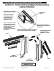
S-5500 SSG and Captured Corner Mullion Installation Instructions Section III: Typical Anchorage Methods CAPTURED SYSTEM SHOWN – SSG SYSTEM SIMILAR TWO PIECE CORNER MULLLIONS Snap-in head and sill fillers after anchor installation. Anchor bolts (type and quantity as required by conditions and loads). SILL Shim as required at anchors and under each vertical mullion. (Shim under setting blocks at heavy lites.) Install PVC pocket filler at frame assembly for captured system.
S-5500 SSG and Captured Corner Mullion Installation Instructions Section III: Typical Anchorage Methods CAPTURED SYSTEM SHOWN – SSG SYSTEM SIMILAR Snap in head and sill fillers after anchor installation. TWO PIECE CORNER MULLLIONS ASSEMBLED CORNER FRAMES Anchor bolts (type and quantity as required by conditions and loads). SILL Shim as required at anchors and under each vertical mullion. (Shim under setting blocks at heavy lites.
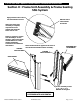
S-5500 SSG and Captured Corner Mullion Installation Instructions Section III: Typical Anchorage Methods BUILDING STRUCTURE CAPTURED SYSTEM SHOWN – SSG SYSTEM SIMILAR Install PVC pocket filler at frame assembly for captured system. HEAD Anchor bolts (type and quantity as required by conditions and loads). PIPE SLEEVE ANCHOR SPLIT CORNER MULLIONS Snap in head and sill fillers after anchor installation. STANDARD HEAD ANCHORAGE EFCO CORPORATION 6/2012 PART NO.
S-5500 SSG and Captured Corner Mullion Installation Instructions Section III: Typical Anchorage Methods CAPTURED SYSTEM SHOWN – SSG SYSTEM SIMILAR BUILDING STRUCTURE Anchor bolts (type and quantity as required by conditions and loads). HEAD PIPE SLEEVE ANCHOR ASSEMBLED CORNER FRAMES SPLIT CORNER MULLIONS Snap in head and sill fillers after anchor installation. STANDARD HEAD ANCHORAGE EFCO CORPORATION 6/2012 PART NO.
S-5500 SSG and Captured Corner Mullion Installation Instructions Section III: Typical Anchorage Methods STEP #3 INSTALL FRAME COMPONENTS – BOLTED WIND LOAD ANCHORS (Dead load anchors similar) When the frame is properly aligned, level and plumb, match drill the slab through the anchor, and install anchor bolts securing the anchor to the building structure. Use the temporary alignment screw to hold the mullion in position until the adjacent corner frame can be installed and anchored.
S-5500 SSG and Captured Corner Mullion Installation Instructions Section III: Typical Anchorage Methods STEP #4 INSTALL FRAME COMPONENTS – BOLTED WIND LOAD ANCHORS (Dead load anchors similar) Stack the adjacent corner frame into the opening, and mate the two-piece mullions together. When the frame is properly aligned and level and plumb, match drill the slab through the anchor, and install anchor bolts securing the anchor to the building structure.
S-5500 SSG and Captured Corner Mullion Installation Instructions Section III: Typical Anchorage Methods STEP #5 INSTALL FRAME COMPONENTS – BOLTED WIND LOAD ANCHORS When the frames are properly aligned and level and plumb, match drill the mullion through the CENTER of the set of slots or holes in the anchor. NOTE: The holes must be a minimum of 1” from the back of the mullion in order to clear any steel reinforcement located inside the system as may be required on a job specific basis.
S-5500 SSG and Captured Corner Mullion Installation Instructions Section IV: Alternate Anchorage Method (Heavy-Duty Anchor Connections) THIS ANCHOR METHOD MUST BE USED WHEN REACTIONS EXCEED 1600 LBS AT INTERMEDIATE VERTICALS AND 800 LBS AT THE JAMBS. Note: The responsible engineer must determine the structural adequacy and type of anchorage method to be used for a given substrate, applied loads, and building movements. The S-5500 has different anchorage options available to meet these conditions.
S-5500 SSG and Captured Corner Mullion Installation Instructions Section IV: Alternate Anchorage Method STEP #1 INSTALL FRAME COMPONENTS This method of anchorage is available for conditions where the standard head and sill anchors or alternate head anchors are not adequate for the given design criteria. Please consult with the structural engineer responsible for the shop drawings for your project. A.
S-5500 SSG and Captured Corner Mullion Installation Instructions Section IV: Alternate Anchorage Method STEP #2 INSTALL FRAME COMPONENTS A. Set the frame with ‘F’ and ‘M’ anchors into the opening. Adjust the frame and place it in the proper position with regard to established benchmarks. B. Using dead load shims under each vertical mullion, level the frame, and set it to the appropriate elevation as indicated in the approved shop drawings. C.
S-5500 SSG and Captured Corner Mullion Installation Instructions Section IV: Alternate Anchorage Method FORMED ALUM. SHEAR BLOCKS SHEAR BLOCKS FOR DROP-ON HEAD ANCHOR BOLTS AS REQ’D. CORNER ‘M’ ANCHOR HORIZ. ATTACHMENT SCREWS ‘M’ ANCHOR DROP-ON HEAD HEAD ANCHOR HORIZ. ATTACHMENT SCREWS DROP-ON SILL CORNER ‘M’ ANCHOR SHEAR BLOCKS FOR DROP-ON SILL ‘M’ ANCHOR ANCHOR BOLTS AS REQ’D. DEAD LOAD SHIMS SILL ANCHOR EFCO CORPORATION 6/2012 PART NO. Y556 FORMED ALUM.
S-5500 SSG and Captured Corner Mullion Installation Instructions Section IV: Alternate Anchorage Method STEP #3 INSTALL FRAME COMPONENTS A. Stack the corner mullions together as shown in Step 2 of Section III. Note: Notching of the second corner mullion to clear the mullion anchors and notching of the heads and sills are required for drop-on application with mullion anchors. (See details on page 26.) B. Repeat step 2 for the adjacent corner frame unit. C.
S-5500 SSG and Captured Corner Mullion Installation Instructions Section IV: Alternate Anchorage Method The corner heads and sills must be notched as shown below to drop straight onto the shear blocks due to the miter. The corner mullion must be notched on each end as shown below to clear the mullion anchor when the corner mullions are stacked.
S-5500 SSG and Captured Corner Mullion Installation Instructions Section V: Glazing Preparation (Captured) STEP #1 SEAL JOINTS AT CORNER HEAD AND SILL AND AT CORNER MULLION A. Seal between the mitered ends for the heads, sills, and the corner mullion to form a water-tight joint as shown in the detail below. The sealant must not obstruct or interfere with the areas of the head or sill where the cover will engage. Note that this is a critical primary seal. B.
S-5500 SSG and Captured Corner Mullion Installation Instructions Section V: Glazing Preparation (Captured) CORNER MULLIONS Apply two beads of sealant in the reglets of the corner mullion where the corner mullion glazing adapter mates into the corner mullion. CAPTURED INTERMEDIATE HORIZONTAL Note: The corner mullion glazing adapter must be set immediately after this step before the sealant begins to cure. INTERMEDIATE HORIZONTAL AT CAPTURED CORNER EFCO CORPORATION 6/2012 PART NO.
S-5500 SSG and Captured Corner Mullion Installation Instructions Section V: Glazing Preparation (Captured) Note: The corner mullion glazing adapter must be set immediately after this step before the sealant begins to cure. CAPTURED HEAD CORNER MULLIONS Seal between the mitered ends of the heads and the corner mullion. Fill all voids completely and tool smooth. Apply two beads of sealant in the reglets of the corner mullion where the corner mullion glazing adapter mates into the corner mullion.
S-5500 SSG and Captured Corner Mullion Installation Instructions Section V: Glazing Preparation (Captured) STEP #2 SET AND ATTACH CORNER MULLION GLAZING ADAPTER A. Apply sealant to the bottom end of the corner mullion glazing adapter as shown in the inset detail A. B. Insert the end of the corner mullion glazing adapter as shown in the main detail below. C. Fill all voids completely and tool the sealant smooth on the bottom end of the corner mullion glazing adapter. D.
S-5500 SSG and Captured Corner Mullion Installation Instructions Section V: Glazing Preparation (Captured) STEP #3 APPLY THERMAL ISOLATORS AND JOINT PLUGS A. Apply thermal isolators in the tongues of the corner mullion glazing adapter. The isolator should run the full length of the adapter. B. Seal the top end of the corner mullion glazing adapter to the mullion. C.
S-5500 SSG and Captured Corner Mullion Installation Instructions Section V: Glazing Preparation (Captured) Tool the sealant smooth across the surface of the joint plugs and on the adapter. Cap seal the fastener heads with sealant. CAPTURED HEAD JOINT PLUG JOINT PLUG CORNER MULLION ADAPTER CORNER MULLIONS HEAD AT CAPTURED CORNER EFCO CORPORATION 6/2012 PART NO.
S-5500 SSG and Captured Corner Mullion Installation Instructions Section V: Glazing Preparation (Captured) CORNER MULLIONS THERMAL ISOLATORS Apply sealant to the horizontal joint plugs and to the adaptor where they come into contact with each other. JOINT PLUG CAPTURED INTERMEDIATE HORIZONTAL JOINT PLUG Cap seal the fastener heads with sealant. CORNER MULLION ADAPTER JOINT PLUG INTERMEDIATE HORIZONTAL AT CAPTURED CORNER EFCO CORPORATION 6/2012 PART NO.
S-5500 SSG and Captured Corner Mullion Installation Instructions Section V: Glazing Preparation (Captured) CORNER MULLIONS Tool the sealant smooth across the surface of the joint plugs and on the adapter. JOINT PLUG CAPTURED INTERMEDIATE HORIZONTAL JOINT PLUG CORNER MULLION ADAPTER INTERMEDIATE HORIZONTAL AT CAPTURED CORNER STEP #4 INSTALL ADAPTERS AND PRESET GASKETS Install the glazing adapters and preset gaskets as required for the outside glazed or inside glazed system. Install glazing as required.
S-5500 SSG and Captured Corner Mullion Installation Instructions Section VI: Glazing Preparation (SSG) STEP #1 SEAL JOINTS AT CORNER HEAD AND SILL AND AT CORNER MULLION A. Seal between the mitered ends of the heads, sills, and the corner mullion to form a water-tight joint as shown in the detail below. The sealant must not obstruct or interfere with the areas of the head or sill where the cover will engage. Note that this is a critical primary seal. B.
S-5500 SSG and Captured Corner Mullion Installation Instructions Section VI: Glazing Preparation (SSG) CORNER MULLIONS Apply two beads of sealant in the reglets of the corner mullion where the corner mullion glazing adapter mates into the corner mullion. SSG INTERMEDIATE HORIZONTAL Note: The corner mullion glazing adapter must be set immediately after this step, before the sealant begins to cure. SSG CORNER MULLION GLAZING ADAPTER INTERMEDIATE HORIZONTAL AT SSG CORNER EFCO CORPORATION 6/2012 PART NO.
S-5500 SSG and Captured Corner Mullion Installation Instructions Section VI: Glazing Preparation (SSG) STEP #2 SET AND ATTACH CORNER MULLION GLAZING ADAPTER A. Apply sealant to the bottom end of the corner mullion glazing adapter. B. Insert the end of the corner mullion glazing adapter as shown in the detail below. C. Fill all voids completely, and tool the sealant smooth on the bottom end of the corner mullion glazing adapter. D.
S-5500 SSG and Captured Corner Mullion Installation Instructions Section VI: Glazing Preparation (SSG) SSG CORNER MULLION GLAZING ADAPTER CORNER MULLIONS SSG SILL Attach the glazing adapter to the corner mullion with the required fasteners. Cap seal the fastener heads with sealant. Fasteners should not exceed 2” from the ends of the adapters and must be spaced at a maximum of 12” o/c. SILL AT SSG CORNER EFCO CORPORATION 6/2012 PART NO.
S-5500 SSG and Captured Corner Mullion Installation Instructions Section VI: Glazing Preparation (SSG) SSG CORNER MULLION GLAZING ADAPTER Seal between the mitered ends of the heads and the corner mullion. Fill all voids completely, and tool smooth. Apply two beads of sealant in the reglets of the corner mullion where the corner mullion glazing adapter mates into the corner mullion.
S-5500 SSG and Captured Corner Mullion Installation Instructions Section VI: Glazing Preparation (SSG) Seal the end of the corner mullion glazing adapter to the corner mullion. SSG HEAD Attach the glazing adapter to the corner mullion with the required fasteners. Cap seal the fastener heads with sealant. Fasteners should not exceed 2” from the ends of the adapters and must be spaced at a maximum of 12” o/c.
S-5500 SSG and Captured Corner Mullion Installation Instructions Section VI: Glazing Preparation (SSG) STEP #3 APPLY GLAZING TAPE TO CORNER MULLION A. Clean all surfaces (and apply primer if necessary) of the glazing adapter that will contact sealant per the sealant manufacturer’s application instructions. B. Apply the glazing tape as shown below. Refer to the approved shop drawings for part numbers and other job specific information.
S-5500 SSG and Captured Corner Mullion Installation Instructions Section VII: Glazing Preparation (Vertical SSG and Captured Horizontal) STEP #1 SEAL JOINTS AT CORNER HEAD AND SILL AND AT CORNER MULLION B. Seal between the mitered ends of the heads, sills, and the corner mullion to form a wate-tight joint as shown in the detail below. The sealant must not obstruct or interfere with the areas of the head or sill where the cover will engage. Note that this is a critical primary seal. C.
S-5500 SSG and Captured Corner Mullion Installation Instructions Section VII: Glazing Preparation (Vertical SSG and Captured Horizontal) CORNER MULLIONS CAPTURED INTERMEDIATE HORIZONTAL CAPTURED INTERMEDIATE HORIZONTAL Seal between the mitered ends of the sills and the corner mullion. Fill all voids completely, and tool smooth. Apply two beads of sealant above and below the horizontal in the reglets of the corner mullion where the corner mullion glazing adapter mates into the corner mullion.
S-5500 SSG and Captured Corner Mullion Installation Instructions Section VII: Glazing Preparation (Vertical SSG and Captured Horizontal) STEP #2 SET AND ATTACH CORNER MULLION GLAZING ADAPTER A. Apply sealant to the bottom end of the corner mullion glazing adapter. B. Insert the end of the corner mullion glazing adapter as shown in the detail below. C. Fill all voids completely, and tool the sealant smooth on the bottom end of the corner mullion glazing adapter. D.
S-5500 SSG and Captured Corner Mullion Installation Instructions Section VII: Glazing Preparation (Vertical SSG and Captured Horizontal) CORNER MULLIONS CAPTURED INTERMEDIATE HORIZONTAL CAPTURED INTERMEDIATE HORIZONTAL Attach the glazing adapters to the corner mullion with the required fasteners. Cap seal the fastener heads with sealant. Fasteners should not exceed 2” from the ends of the adapters and must be spaced at a maximum of 12” o/c.
S-5500 SSG and Captured Corner Mullion Installation Instructions Section VII: Glazing Preparation (Vertical SSG and Captured Horizontal) Attach the glazing adapter to the corner mullion with the required fasteners. Cap seal the fastener heads with sealant. Fasteners should not exceed 2” from the ends of the adapters and must be spaced at a maximum of 12” o/c. Seal the end of the corner mullion glazing adapter to the corner mullion.
S-5500 SSG and Captured Corner Mullion Installation Instructions Section VIII: Exterior Cover & Drive-In Gasket Installation for Captured System STEP #1 APPLY TEMPORARY GLAZING RETAINERS AT CORNERS A. Position the temporary glazing retainers at quarter points along the height of the D.L.O. at the corner. The maximum spacing for the retainers should not exceed 30” center to center. B. Match drill the corner mullion through the hole in the retainer, and apply the temporary glazing retainers as shown below.
S-5500 SSG and Captured Corner Mullion Installation Instructions Section VIII: Exterior Cover & Drive-In Gasket Installation for Captured System STEP #2 APPLY HORIZONTAL PRESSURE COVERS AT HEAD AND SILL A. Plug the ends of the horizontal pressure covers including heads, intermediates, and sills with backer rod. Recess the backer rod at least 1/4” from each end and apply a generous amount of sealant to cover the ends of the covers. B.
S-5500 SSG and Captured Corner Mullion Installation Instructions Section VIII: Exterior Cover & Drive-In Gasket Installation for Captured System SILL CONDITION SHOWN, HEAD SIMILAR EXTERIOR WEDGE GASKETS CAPTURED SILL SILL PRESSURE COVER Apply a continuous bead of sealant. (Approx. 1/16” diameter). HEAD AND SILL HORIZONTAL EFCO CORPORATION 6/2012 PART NO.
S-5500 SSG and Captured Corner Mullion Installation Instructions Section VIII: Exterior Cover & Drive-In Gasket Installation for Captured System STEP #3 APPLY CORNER MULLION PRESSURE PLATE A. Remove any temporary glazing retainers that were installed at the corner mullion during previous steps. B. Seal all holes in the corner mullion where the temporary glazing retainers were installed with sealant. C. Apply the preset gaskets to the corner mullion pressure plate.
S-5500 SSG and Captured Corner Mullion Installation Instructions Section VIII: Exterior Cover & Drive-In Gasket Installation for Captured System STEP #4 APPLY CORNER MULLION PRESSURE PLATE A. Position the pressure plate so there is an equal space on each end of the pressure plate at the head and sill covers. B. Screw down the corner mullion pressure plate with the required fasteners at 6” center to center. Torque all fasteners to 80 inch-pounds.
S-5500 SSG and Captured Corner Mullion Installation Instructions Section VIII: Exterior Cover & Drive-In Gasket Installation for Captured System STEP #5 INSTALL INTERMEDIATE PRESSURE COVERS A. Insert backer rod into the ends of the horizontal. Recess the backer rod at least 1/4” into the inside area of the cover. B. Apply sealant to the ends of the cover, filling the voids at the end. C.
S-5500 SSG and Captured Corner Mullion Installation Instructions Section VIII: Exterior Cover & Drive-In Gasket Installation for Captured System STEP #6 APPLY WEDGE GASKETS A. Apply the exterior wedge gaskets at the intermediate horizontals. Apply the gasket to the top of the horizontal first, then to the underside. Refer to “Section X: Exterior Cover & Drive-In Gasket Installation” beginning on page 49 of the Series 5500 Outside Glazed Installation Instructions for more information.
S-5500 SSG and Captured Corner Mullion Installation Instructions Section IX: Vertical Splice Joints Installation for Captured System STEP #1 LOCATE SPLICE JOINTS A. Splice joints should occur at spandrel areas (if possible). Refer to the approved shop drawings for actual locations. B. The mullion splice must be field assembled in the top of the lower mullion after the corner frames have been set into the opening and anchored at the sill. C. GENERAL NOTE: The following pages depict a splice joint of 1/2”.
S-5500 SSG and Captured Corner Mullion Installation Instructions Section IX: Vertical Splice Joints Installation for Captured System NOTE: All anchors must be fixed before glazing begins. EFCO CORPORATION 6/2012 PART NO.
S-5500 SSG and Captured Corner Mullion Installation Instructions Section IX: Vertical Splice Joints Installation for Captured System STEP #2 ATTACH MULLION SPLICE SLEEVES A. Clean all surfaces that will contact sealant per the sealant manufacturer’s instructions making sure to remove all oils and debris from contact surfaces. B. Apply bond breaker tape to the corner mullion splice sleeve. C. Install the lower section of the corner frames as instructed in previous sections. D.
S-5500 SSG and Captured Corner Mullion Installation Instructions Section IX: Vertical Splice Joints Installation for Captured System MULLION SPLICE SLEEVE BOND BREAKER TAPE SPLICE ATTACHMENT SCREWS (cap seal) LOWER 2-PIECE CORNER MULLION ASSEMBLY EFCO CORPORATION 6/2012 PART NO.
S-5500 SSG and Captured Corner Mullion Installation Instructions Section IX: Vertical Splice Joints Installation for Captured System STEP #3 ALIGN AND STACK ASSEMBLED FRAMES A. Align the pre-assembled frames, and stack together at the splice joints. B. Position the mullions to the appropriate elevation with regard to established benchmarks, and shim or fix the mullions at their respective dead load anchor points. C. Install both of the upper adjacent frames before sealing the mullion splice joints. D.
S-5500 SSG and Captured Corner Mullion Installation Instructions Section IX: Vertical Splice Joints Installation for Captured System STEP #4 SEAL MULLION SPLICE SLEEVE A. Apply sealant into the mullion splice joint, and tool the joint. Do not obstruct the corner mullion adapter reglets. The sealant must extend back 1” along the side of the mullion from the glazing pocket. Apply sealant into the mullion splice joint, and tool smooth. Extend sealant back 1” from glazing pocket.
S-5500 SSG and Captured Corner Mullion Installation Instructions Section IX: Vertical Splice Joints Installation for Captured System STEP #5 ATTACH MULLION ADAPTER AND ADAPTER SPLICE SLEEVE A. Install the corner mullion adapter as shown in “Section V Glazing Preparation (Captured)” of this manual. The adapter should be cut to mullion length, starting and stopping at the mullion splice joint. B. Apply bond breaker tape to the mullion adapter splice sleeve. C.
S-5500 SSG and Captured Corner Mullion Installation Instructions Section IX: Vertical Splice Joints Installation for Captured System STEP #6 APPLY PRESET ISOLATORS AND INTERIOR GASKETS A. B. Apply the interior preset gaskets and isolator gaskets per “Section V Glazing Preparation (Captured)” of this manual. The gaskets will run continuously spanning the splice joint. The gaskets should be set immediately after applying sealant to the splice joint to avoid interference with cured sealant. C.
S-5500 SSG and Captured Corner Mullion Installation Instructions Section IX: Vertical Splice Joints Installation for Captured System STEP #7 APPLY PRESSSURE PLATES A. Apply the preset gaskets to the pressure plates. Cut the gaskets flush with both ends of the pressure plates. B. Install the lower pressure plate starting at the sill with pressure plate screws. Locate the screws 6” o.c. and at a maximum of 3” from the ends of the pressure plate. Torque the screws to 80 inch-pounds (6.6 foot-pounds). C.
S-5500 SSG and Captured Corner Mullion Installation Instructions Section IX: Vertical Splice Joints Installation for Captured System STEP #8 SEAL PRESSSURE PLATES A. Apply backer rod into the joint between the ends of the pressure plates at the splice joint to backup the sealant applied in step 8-B. B. Apply sealant into the joint ensuring to thoroughly wet the ends of the pressure plates. Apply enough sealant to provide a minimum of 1/4” sealant contact surface on the ends of the pressure plates.
S-5500 SSG and Captured Corner Mullion Installation Instructions Section IX: Vertical Splice Joints Installation for Captured System STEP #9 APPLY EXTERIOR CORNER COVER SPLICE A. Apply .062 x .375 foam tape with pressure sensitive adhesive on both sides to the cover splice as shown below. B. Apply bond breaker tape to the splice (optional) if the joints of the covers are to be sealed. C. Apply sealant to the splice between the rows of tape to permanently adhere the splice to the cover. D.
S-5500 SSG and Captured Corner Mullion Installation Instructions Section IX: Vertical Splice Joints Installation for Captured System STEP #10 APPLY EXTERIOR CORNER COVERS A. Snap-on the upper corner snap cover first, aligning it with the top of the corner mullion. If the cover slides downward, apply a small amount of sealant in the snap areas, and temporarily tape the cover in position. B. Snap-on the lower cover next, allowing for the proper splice joint spacing.
S-5500 SSG and Captured Corner Mullion Installation Instructions Section IX: Vertical Splice Joints Installation for Captured System STEP #11 APPLY CAULKING TO EXTERIOR CORNER COVER JOINT (OPTIONAL) A. The corner cover splice will be supplied with a finish to match the exterior finish of the curtain wall. A caulk joint is not required at the cover splice joint. As an option, the erecter may choose to apply sealant to the corner cover splice joint.
S-5500 SSG and Captured Corner Mullion Installation Instructions Section X: Vertical Splice Joints Installation for SSG System STEP #1 LOCATE SPLICE JOINTS A. Splice joints should occur at spandrel areas (if possible). Refer to the approved shop drawings for actual locations. The vertical structural glazed system should be spliced as close as possible to a horizontal to minimize the shear stress imposed on the vertical structural silicone joint. B.
S-5500 SSG and Captured Corner Mullion Installation Instructions Section X: Vertical Splice Joints Installation for SSG System Note: The vertical structural glazed system should be spliced as close as possible to a horizontal to minimize the shear stress imposed on the vertical structural silicone joint. NOTE: All anchors must be fixed before glazing begins. EFCO CORPORATION 6/2012 PART NO.
S-5500 SSG and Captured Corner Mullion Installation Instructions Section X: Vertical Splice Joints Installation for SSG System STEP #2 ATTACH MULLION SPLICE SLEEVES A. Clean all surfaces that will contact sealant per the sealant manufacturer’s instructions making sure to remove all oils and debris from contact surfaces. B. Apply bond breaker tape to the corner mullion splice sleeve. C. Install the lower section of the corner frames as instructed in previous sections. D.
S-5500 SSG and Captured Corner Mullion Installation Instructions Section X: Vertical Splice Joints Installation for SSG System STEP #3 ALIGN AND STACK ASSEMBLED FRAMES A. Align the pre-assembled frames, and stack together at the splice joints. B. Position the mullions to the appropriate elevation with regard to established benchmarks, and shim or fix the mullions at their respective dead load anchor points. C. Install both of the upper adjacent frames before sealing the mullion splice joints. D.
S-5500 SSG and Captured Corner Mullion Installation Instructions Section X: Vertical Splice Joints Installation for SSG System STEP #4 SEAL MULLION SPLICE B. Apply sealant into the mullion splice joint, and tool the joint. Do not obstruct the corner mullion adapter reglets. The sealant must extend back 1” along the side of the mullion from the glazing pocket. 2-PIECE CORNER MULLION ASSEMBLY Apply sealant into the mullion splice joint, and tool smooth. Extend sealant back 1” from glazing pocket.
S-5500 SSG and Captured Corner Mullion Installation Instructions Section X: Vertical Splice Joints Installation for SSG System STEP #5 ATTACH MULLION ADAPTER A. Install the SSG corner mullion adapters as shown in “Section VI Glazing Preparation (SSG)” of this manual. The adapters should be cut to mullion length, starting and stopping at the mullion splice joint. B. Apply sealant to fill the void between the SSG corner mullion adapters. C. Tool the joint smooth as shown in the inset detail.
S-5500 SSG and Captured Corner Mullion Installation Instructions Section XI: Glazed SSG Corners STEP #1 APPLY SPACERS, SETTING CHAIRS, AND SETTING BLOCKS A. Install the setting chairs and blocks as required. Refer to the approved shop drawings for locations. B. Apply the glazing tape as shown on page 41 in Section VI of this manual. Refer to the approved shop drawings for part numbers and other job specific information. VERTICAL SPACER GLAZING TAPE Setting chair and blocks located per shop drawings.
S-5500 SSG and Captured Corner Mullion Installation Instructions Section XI: Glazed SSG Corners VERTICAL SPACER GLAZING TAPE CAPTURED HORIZONTAL MULLION Setting blocks located per shop drawings. Butt horizontal glazing gaskets into the vertical spacers. CAPTURED HORIZONTAL MULLION HORIZONTAL PRESET GLAZING GASKET Glazing tape spacer runs through splice joint HORIZONTAL PRESET GLAZING GASKETS Notch darts on end of horizontal gaskets.
S-5500 SSG and Captured Corner Mullion Installation Instructions Section XI: Glazed SSG Corners SSG VERTICAL MULLION VERTICAL SPACER GLAZING TAPE Setting chair and blocks located per shop drawings. Butt horizontal spacers into the vertical spacers. SSG SILL Notch darts on end of spacers. HORIZONTAL PRESET SPACER GASKET 4-SIDED SSG SILL (HEAD SIMILAR) EFCO CORPORATION 6/2012 PART NO.
S-5500 SSG and Captured Corner Mullion Installation Instructions Section XI: Glazed SSG Corners SSG VERTICAL MULLION VERTICAL SPACER GLAZING TAPE Setting blocks located per shop drawings. Butt horizontal glazing gaskets into the vertical spacers. CAPTURED SILL HORIZONTAL PRESET GLAZING GASKET Notch darts on ends of horizontal gaskets. Setting blocks located per shop drawings. VERTICAL SSG AND CAPTURED SILL (HEAD SIMILAR) EFCO CORPORATION 6/2012 PART NO.
S-5500 SSG and Captured Corner Mullion Installation Instructions Section XI: Glazed SSG Corners STEP #2 SET GLAZING INFILL, APPLY EXTERIOR GASKETS WHERE REQUIRED, TEMPORARY GLAZING RETAINERS, APPLY SSG JOINTS A. Set glazing infill. Refer to Section IX “Glazing Installation” of the Series 5500 Silicone Structural Glazed Curtain Wall Installation Instructions for detailed information for cleaning and priming of glazing materials, substrate, and glazing installation. B.
S-5500 SSG and Captured Corner Mullion Installation Instructions Section XI: Glazed SSG Corners GLAZING INFILL SSG VERTICAL MULLION GLAZING INFILL SSG SILL Caulk joints at the weather seals must blend to form a continuous seal and marry into the perimeter caulk joint. 4-SIDED SSG SILL (HEAD SIMILAR) EFCO CORPORATION 6/2012 PART NO.
S-5500 SSG and Captured Corner Mullion Installation Instructions Section XI: Glazed SSG Corners GLAZING INFILL SSG VERTICAL MULLION GLAZING INFILL CAPTURED SILL Caulk joints at the weather seals must blend to form a continuous seal and marry into the perimeter caulk joint. VERTICAL SSG AND CAPTURED SILL (HEAD SIMILAR) EFCO CORPORATION 6/2012 PART NO.
S-5500 SSG and Captured Corner Mullion Installation Instructions Section XI: Glazed SSG Corners SSG VERTICAL MULLION GLAZING INFILL GLAZING INFILL Caulk joints at the weather seals must blend to form a continuous seal. 4-SIDED SSG EFCO CORPORATION 6/2012 PART NO.
S-5500 SSG and Captured Corner Mullion Installation Instructions Section XI: Glazed SSG Corners GLAZING INFILL SSG VERTICAL MULLION GLAZING INFILL CAPTURED HORIZONTAL Caulk joints at the weather seals must blend to form a continuous seal. CAPTURED INTERMEDIATE HORIZONTALS AT SSG CORNER EFCO CORPORATION 6/2012 PART NO.