Series 5600 outside glazed curtain wall Installation Instructions Part NO.
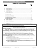
Series 5600 Outside Glazed Installation Instructions TABLE OF CONTENTS SECTION PAGE I. General Notes & Guidelines…………………………………………………………………………………….3-4 II. Mullion Anchor & Frame Assembly…………………………………………………………………………..5 III. Anchor Installation…………………………………………………………………………………………………6-7 IV. Perimeter Application……………………………………………………………………………………………..8 V. Frame Assembly…………………………………………………………………………………………………….9-13 VI. Glazing Preparation……………………………………………………………………………………………….14-17 1.
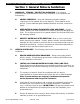
Series 5600 Outside Glazed Installation Instructions Section I: General Notes & Guidelines I. II. HANDLING / STORING / PROTECTING ALUMINUM - The following precautions are recommended to assure early acceptance of your products and workmanship. A. HANDLE CAREFULLY - Store with adequate separation between components so the material will not rub together. Store material off the ground. Protect materials against weather elements and other construction trades. B.
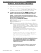
Series 5600 Outside Glazed Installation Instructions Section I: General Notes & Guidelines F. Follow EFCO framing installation and glazing instructions. G. Verify contents of all material shipments received upon arrival. Verify quantities and correct finishes. NOTIFY EFCO IMMEDIATELY OF ANY DISCREPANCIES OR DAMAGE, THAT MAY HAVE OCCURRED. H. Throughout these instructions the term “SEALANT” will appear.
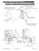
Series 5600 Outside Glazed Installation Instructions Section II: Mullion Anchor & Frame Assembly Anchor at head allows for movement (refer to shop drawings). The erector must supply and apply bond breaker tape across the face of the anchor to prevent three-sided adhesion. “T” Anchor at Intermediate Mullion Line of critical perimeter sealant is shown dotted. “F” Anchor at Jamb Condition Type, size, and location of anchor bolts as shown on shop drawings per structural requirements.
Series 5600 Outside Glazed Installation Instructions Section III: Anchor Installation Apply Appropriate Anchors A.) B.) C.) Attach anchors to the mullion with temporary alignment screws as shown in the detail below. Install the vertical mullions into position and attach anchors to the building structure per approved shop drawings. After final alignment of the mullion, align drill the mullion through the best hole location available.
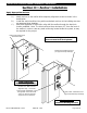
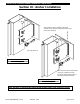
Series 5600 Outside Glazed Installation Instructions Section III: Anchor Installation 1" MIN. A steel plate is factory welded to the steel channel and is sized per job requirements. Refer to the shop drawings. 1" MIN. See page #6 of 23 Dead Load Anchor Bolted to building structure Size and locate anchor bolts based on the job conditions and the structural requirements. Refer to the approved shop drawings.
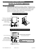
Series 5600 Outside Glazed Installation Instructions Section IV: Perimeter Application Determine Installation Method A.) Two types of perimeter applications are possible, including “F” perimeter anchors or mullion anchors with continuous pressure plate pocket fillers. “F” perimeter anchors should only be used in small “punched” openings that can be assembled on the floor and set into the opening.
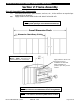
Series 5600 Outside Glazed Installation Instructions Section V: Frame Assembly Step #1 Assemble Frame Components A.) Assemble shear blocks, splice sleeves, anchors, etc., to the mullions as required per approved shop drawings. B.) Apply sealant to the shear blocks and attach horizontal rails. Note: On long runs, check overall frame dimensions at every fifth opening to avoid dimensional build-up. Overall Dimension Check ** Dimension Check Every 5 Units Interior tubular horizontals are cut D.L.O. – 1/32”.
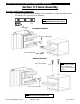
Series 5600 Outside Glazed Installation Instructions Section V: Frame Assembly Step #2 Install Frame Components A.) Refer to the approved shop drawings for job conditions. Install assembled frames according to the approved shop drawings. Note: Shear block must be leveled and perpendicular to the vertical. Level Shear Block Concealed Fastener #14 X 1/2” HWH SMS #10 X 3/4” FH SMS Exposed Fastener #8 X 5/8” FH SMS Note: Fasten in hidden location where possible.
Series 5600 Outside Glazed Installation Instructions Section V: Frame Assembly Step #2 Install Frame Components A.) Refer to the approved shop drawings for job conditions. Install assembled framed according to the approved shop drawings. The approved shop drawings will also indicate the location of horizontal slip-on rails. Note: Frames are designed to stack from left to right, horizontals slide on ONLY in the last D.L.O. unless otherwise noted on the approved FINAL drawings.
Series 5600 Outside Glazed Installation Instructions Section V: Frame Assembly Step #2 Optional “Roll – On Horizontal” Components A.) Refer to the approved shop drawings for job conditions. Install assembled frames according to the approved shop drawings. The approved shop drawings will also indicate the location of “Roll – On” horizontal. Note: Shear block must be leveled and perpendicular to the vertical.
Series 5600 Outside Glazed Installation Instructions Section V: Frame Assembly Pin horizontal to face of shear block w/ supplied tek screw(s) Pin through under side of shear block Note: Horizontal must be leveled and perpendicular to the vertical. Fully tighten all screws until completely seated. EFCO CORPORATION 7/2012 PART NO.
Series 5600 Outside Glazed Installation Instructions Section V: Frame Assembly Snap in filler. Rotate in and snap filler. EFCO CORPORATION 7/2012 PART NO.
Series 5600 Outside Glazed Installation Instructions Section VI: Glazing Preparation Step #1 Install Thermal Isolator A.) Remove thermal isolator from reels and allow to relax and shrink. DO NOT stretch isolator prior to installation. B.) Install the 90 durometer PVC thermal isolator into position in the screw raceway of the vertical and horizontal mullions. C.) Run the vertical isolators continuous and butt together as required. Run the horizontal isolator to the ends of the horizontal members.
Series 5600 Outside Glazed Installation Instructions Section VI: Glazing Preparation Step #3 Seal Slip-In Horizontal Joints A.) At slip-in horizontals, install backer rods and completely seal over the notch in the horizontal framing members as indicated. Apply sealant a minimum of 2” in each direction from the intersecting members. 2" Min. Elevation of joinery, at slip on horizontal, prior to setting the infill.
Series 5600 Outside Glazed Installation Instructions Section VI: Glazing Preparation Step #4 Install Glazing Infill Adaptors A.) Prior to installing the glazing adaptors, seal the entire gasket raceway with sealant. B.) Snap glazing adaptors in place into sealant starting with the verticals. Allow at least 1/8” clearance from the bottom of the glazing adaptor to the top of the joint plug to allow for weepage. C.) Butter the ends of the horizontal adaptors prior to setting into position.
Series 5600 Outside Glazed Installation Instructions Section VI: Glazing Preparation Step #5 Install Glazing Gaskets In Mullions A.) Remove glazing gaskets from the reel and allow to relax and shrink. B.) Apply sealant into raceway a minimum of 2” in each direction from the corner. (Refer to illustration below.) C.) Once the gaskets have relaxed, cut and install into position. Vertical gaskets must be cut vertical D.L.O. plus 1 ¾”. Place into position starting at the center of the D.L.O.
Series 5600 Outside Glazed Installation Instructions Section VII: Glazing Installation Note: All anchors must be “FIXED” before glazing installation begins. Step #1 Prepare Exterior Pressure Plates A.) Remove exterior gasket material from the reel and allow to relax and shrink. B.) Apply glazing gaskets to the pressure plates.
Series 5600 Outside Glazed Installation Instructions Section VII: Glazing Installation Step #3 Install Infill Glazing Materials A.) Install proper infill into the opening using suction cups to gently lower the infill material onto the setting blocks. Note: Do Not Seal the Setting Blocks to the Tongue of Horizontal Mullion. B.) C.) Position the infill in the center of the opening maintaining a ½” glass bite around the entire perimeter.
Series 5600 Outside Glazed Installation Instructions Section VII: Glazing Installation Step #5 Install Side Blocks A.) Install and position side “W” blocks in the jamb cavity as indicated. Stretch “W” side blocks and insert into pocket. Typical at both jambs. Step #6 Apply Exterior Pressure Plates A.) First attach the vertical pressure plates and then the horizontal pressure plates into position using #13 X 5/8” S.S. Hex Washer Head screws. Locate screws 6” O.C.
Series 5600 Outside Glazed Installation Instructions Section XIII: Vertical Splice Joints Step #1 Locate Splice Joints A.) Splice joints should occur at the spandrel areas (if possible). Refer to approved final shop drawings for actual locations. B.) Depending on the specific job requirements, splice sleeves may be shop or field assembled in the top of the lower mullion. If materials are field fabricated, use the following assembly instructions.
Series 5600 Outside Glazed Installation Instructions Section XIII: Vertical Splice Joints Upper mullion is “stabbed” onto lower mullion splice. Splice sleeve will vary with the system mullion depth. Apply “Bond Breaker Tape” to splice and insert into lower mullion. Seal between mullion back members and tongues, then tool sealant into joint and smooth. After infill is in place, apply the pressure plates and seal between pressure plates. Then tool sealant into joint and smooth.
Series 5600 Outside Glazed Installation Instructions Section IX: Exterior Cover Installation Step #1 Apply Exterior Covers A.) Locate and apply vertical covers as shown on the approved Final shop drawings. Engage one side, then use the mallet and block to engage the opposite side. B.) Center the horizontal snap cover in the opening and apply it in the same manner. Gaps at the ends should be split equally and are to allow for thermal movement and weepage. Note: Exterior horizontal snap covers are cut D.L.
Series 5600 Outside Glazed Installation Instructions Section IX: Exterior Cover Installation Step #2 Secure Exterior Covers A.) On vertical covers 1” in depth and over, it is necessary to install a 1/16” X 5/16” roll pin at the horizontal cover locations to prevent slippage. B.) On horizontal covers 1” in depth and over, it is necessary to mechanically attach the cover to the pressure plate similar to what is shown below to insure against disengagement of cover from pressure plate. 1” and up.
Series 5600 Outside Glazed Installation Instructions Section X: Reinforcing Step #1 Install Reinforcing Steel A.) At large spans or in high wind load areas, internal steel reinforcement may be necessary. Reinforcement steel requirements will vary from job to job. Please reference the approved final shop drawings for steel reinforcement requirements. B.) When steel reinforcement is factory installed into the mullions, fasteners will be used to prevent damage or slippage of the steel during shipment.