Series 5600 Silicone structural glazed Installation Instructions Part NO.
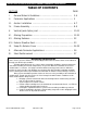
Series 5600 Silicone Structural Glazed Installation Instructions SECTION TABLE OF CONTENTS PAGE I. General Notes & Guidelines ……………………………………………… 3-4 II. Perimeter Applications ……………….……………………………………… 5 III. Anchor Installation ……………………………………………………………. 6-7 IV. Frame Assembly …….…………………………………………………………. 8-9 V. Vertical/Jamb Splice Joint …………………………………………………. 10-11 VI. Glazing Preparation …………………………………………………………… 12-21 VII. Glazing Retainer...……………………………………………………………… 22 VIII. Exterior Weather Seal.
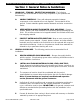
Series 5600 Silicone Structural Glazed Installation Instructions Section I: General Notes & Guidelines I. II. HANDLING / STORING / PROTECTING ALUMINUM - The following precautions are recommended to assure early acceptance of your products and workmanship. A. HANDLE CAREFULLY - Store with adequate separation between components so the material will not rub together. Store material off the ground. Protect materials against weather elements and other construction trades. B.
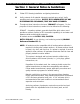
Series 5600 Silicone Structural Glazed Installation Instructions Section I: General Notes & Guidelines F. Follow EFCO framing installation and glazing instructions. G. Verify contents of all material shipments received upon arrival. Verify quantities and correct finishes. NOTIFY EFCO IMMEDIATELY OF ANY DISCREPANCIES OR DAMAGE, THAT MAY HAVE OCCURRED. H. Throughout these instructions the term “SEALANT” will appear.
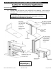
Series 5600 Silicone Structural Glazed Installation Instructions Section II: Perimeter Applications Perimeter Applications A.) Maintain caulk joint as shown in the “APPROVED” shop drawings. Unless specified otherwise, a 3/8” minimum perimeter caulk joint is recommended by most sealant manufacturers. Note: Anchoring surfaces of perimeter constructions must be level and plumb within the adjustment limits of the jamb, head, or sill. See “APPROVED” shop drawings for adjustment.
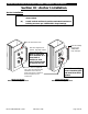
Series 5600 Silicone Structural Glazed Installation Instructions Section III: Anchor Installation Anchor Installation Note: A.) Attach anchors to mullions with temporary screws as shown below. B.) Install vertical mullions in position and attach anchors to building structure per “APPROVED” shop drawings. 1/16” Horseshoe shim After final alignment of mullion, align drill mullion in best hole location. Weld to building structure per “APPROVED” shop drawings.
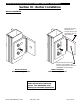
Series 5600 Silicone Structural Glazed Installation Instructions Section III: Anchor Installation Anchor Installation Steel plate is factory welded to steel channel sized per job requirement refer to shop drawings Size and locate anchor bolts based on job conditions and structural requirements reference “APPROVED” shop drawings. Wind Load Anchor Bolted to building structure Dead Load Anchor Bolted to building structure Note: Elevations of slab must be within adjustments of anchoring system.
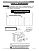
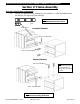
Series 5600 Silicone Structural Glazed Installation Instructions Section IV: Frame Assembly Frame Assembly A.) Assemble shear blocks, sleeves, anchors, etc., to mullions as required. Attach horizontals to form the frames or sections per “APPROVED” shop drawings. B.) Attach horizontal rails to shear blocks. Note: On long runs, check overall frame dimensions at every fifth opening to avoid dimensional build-up. Overall Dimension Check ** Dimension Check Every 5 Units Interior tubular horizontals are cut D.
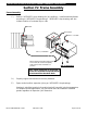
Series 5600 Silicone Structural Glazed Installation Instructions Section V: Frame Assembly Step #2 Install Frame Components A.) Refer to the approved shop drawings for job conditions. Install assembled frames according to the approved shop drawings. Note: Shear block must be leveled and perpendicular to the vertical. Level Shear Block Concealed Fastener #14 X 1/2” HWH SMS #10 X 3/4” PH SMS Exposed Fastener #8 X 5/8” FH SMS Note: Fasten in hidden location where possible.
Series 5600 Silicone Structural Glazed Installation Instructions Section IV: Frame Assembly Frame Assembly C.) Refer to “APPROVED” shop drawings for job conditions. Install assembled frames according to “APPROVED” shop drawings. “APPROVED” shop drawings will also indicate location of horizontal slip-on rails. Sealant Shear Block " 1/2 N. I M #8 X ¾” FH SMS #14 X 1/2” HWHSMS When applying horizontal mullion with front notch, fill notched completely with sealant, after horizontal is in position.
Series 5600 Silicone Structural Glazed Installation Instructions Section V: Vertical Jamb Splice Joints Vertical Jamb Splice Joints A.) Splice joints should occur at spandrel areas. Mullion splice joints for this system are not designed to compensate for varying floor levels. (Reference “APPROVED” shop drawings for allowable adjustment, i.e., anchors.) B.) Splice joint width should be based on sealant movement capabilities and the following formula.
Series 5600 Silicone Structural Glazed Installation Instructions Section V: Vertical Jamb Splice Joints Vertical Splice Joints Note: Butt glazed mullion splice joints should occur at spandrel areas. Where head clearance is insufficient to allow top mullions to be lifted over sleeve. A retractable sleeve will be used. The sleeve is taped in the top mullion and dropped to stop screw in mullion below. F.) Do not match drill anchors until a check of expansion joints and wall installation is made.
Series 5600 Silicone Structural Glazed Installation Instructions Section VI: Glazing Preparation Glazing Preparation A.) Install PVC thermal isolator (90 Durometer) in horizontal and vertical, run continuously, and butt joint as required. Note: All PVC thermal isolators should be removed from the reels and allowed to shrink prior to installation. Seal all connecting surfaces of horizontal and vertical with sealant for installation of mullion plugs.
Series 5600 Silicone Structural Glazed Installation Instructions Section VI: Glazing Preparation Glazing Preparation Tool sealant at horizontal ends Seal face of mullion and tongue of horizontal with sealant prior to installation of joint plug. (Tool sealant into mullion groove.) Joint plug Note: All sealant shown on this detail must be done just prior to installation of joint plug. Keep free from loose debris. EFCO CORPORATION 7/2012 PART NO.
Series 5600 Silicone Structural Glazed Installation Instructions Section VI: Glazing Preparation Glazing Preparation Tool sealant at horizontal ends Seal face of mullion and tongue of horizontal with sealant prior to installation of joint plug. (Tool sealant into mullion groove.) Joint plug Note: All sealant shown on this detail must be done just prior to installation of joint plug. Keep free from loose debris. EFCO CORPORATION 7/2012 PART NO.
Series 5600 Silicone Structural Glazed Installation Instructions Section VI: Glazing Preparation Glazing Preparation Seal at Captured Vertical Jambs Prior to installation of the joint plug, apply sealant on all joint plug contact surfaces. After installation of the plugs, reseal joints and tool excess sealant to provide a smooth surface Provide downward slope with sealant without interfering with edge of glass, to allow drainage of condensation.
Series 5600 Silicone Structural Glazed Installation Instructions Section VI: Glazing Preparation Installation of Glazing Adaptors at Openings for ¼” Infill A.) Position vertical adaptor as shown. Place horizontal adaptors between verticals. Seat adaptors by applying sealant to all four corners. Seal at Captured Glazing Adaptors Cut Formula Vertical = D.L.O. + 1” Horizontal = D.L.O. – 1/16” Note: MIN. 1/8" Continuously seal gasket raceway with sealant prior to installing adaptors.
Series 5600 Silicone Structural Glazed Installation Instructions Section VI: Glazing Preparation Installation of Spandrel Glazing Adaptors Vertical Adaptor Cut Length Without Expansion Joint = D.L.O. + 1” Set all adaptors in a continuous bead of sealant. Vertical Adaptor Cut Length With Expansion Joint; See “APPROVED” Shop Drawings Horizontal Adaptor Cut Length = D.L.O. – 1/16” Attach vertical adaptor to mullion with #8 X 1 ¼” FHSMS Stainless Steel screw at a minimum 18” O.C. (Seal heads w/ silicone.
Series 5600 Silicone Structural Glazed Installation Instructions Section VI: Glazing Preparation Apply Preset Glazing Gaskets to Mullions Note: A.) Apply sealant in raceway a minimum of 2” each way at all corners. (Ref. to page 16) B.) Remove glazing gaskets from reel and allow to shrink. C.) Cut vertical D.L.O. + 1 ¾”. D.) Cut horizontal D.L.O. + ½”. E.) Seal all gasket corners; pull horizontal gasket back, seal end and jam into vertical gasket to insure a snug fit. See detail at right.
Series 5600 Silicone Structural Glazed Installation Instructions Section VI: Glazing Preparation Note: SSG Vertical Splice Locations EFCO recommends that Vertical Splice Line should be below the Intermediate Horizontal Member, this will Minimize Shear Stress at the Structural Seal Line. Air Seal at Expansion Joint Joint Plug Expansion Joint Splice Sleeve Note: Install air seal at expansion joint. At corners, use more than one air seal as required. Miter to fit corner. Clean A.
Series 5600 Silicone Structural Glazed Installation Instructions Section VI: Glazing Preparation Position Glass Infill A.) Set glass in framing opening, tight against interior gaskets, and position squarely on setting blocks. Customer / Installer Note: EFCO setting blocks are typically 4" in length with different depths.
Series 5600 Silicone Structural Glazed Installation Instructions Section VI: Glazing Preparation Attach Pressure Plates A.) Apply glazing gaskets to pressure plates. B.) Gaskets applied to vertical pressure plates must be cut flush at both ends, except in multi-story applications, gaskets must extend 1” beyond the end at expansion joints. CL MULL 2 1/4" 4" TYP. 1/4" OPTIONAL WEEP HOLES 5/16” weep holes Drill 3 side by side centered 4” off each end of the pressure plate.
Series 5600 Silicone Structural Glazed Installation Instructions Section VII: Glazing Retainer Temporary Retainers Silicone Structural Glazed Temporary Retainer A.) Temporary retainers are available from EFCO. The location of temporary exterior infill retainers should be at a maximum spacing of 24” on center, or two per lite. * If high wind conditions are anticipated, additional retainers may be required; erector should consult the sealant and/or infill supplier for spacing recommendations.
Series 5600 Silicone Structural Glazed Installation Instructions Section VIII: Exterior Weather Seal Apply Exterior Weather Seal A.) Install backer rod between the two infill units (insulated and monolithic). B.) Apply exterior weather seal as recommended by the sealant manufacturer. Note: Seal up to temporary retainers. After the structural sealant cures, remove the temporary retainers and seal remaining gaps. 1" INFILL Backer Rod EFCO CORPORATION 7/2012 PART NO.
Series 5600 Silicone Structural Glazed Installation Instructions Section IX: Snap-On Exterior Covers Snap-On Exterior Cover A.) Set horizontal covers as shown on “APPROVED” shop drawings. ½” Drill 5/16” diameter weep holes in horizontal covers at 2” from vertical covers. Caution: Care must be taken to avoid damage to covers during installation. Use a nominal 12” long, 2” X 4” block, and mallet or hammer to seat cover. Approx. 12” long wood block. Backer Rod at splice. Mallet or Hammer B.) C.
Series 5600 Silicone Structural Glazed Installation Instructions Section IX: Snap-On Exterior Covers Snap-On Exterior Cover Horizontal cover Vertical cover Note: Horizontal covers with a depth of 1” or more must be mechanically attached similar to detail below. Equal space both ends of horizontal cover 1/16” X 5/16” roll pin at center of cut length is recommended to prevent slippage. Roll pin can be located at horizontal cover to eliminate exposure. EFCO CORPORATION 7/2012 PART NO.
Series 5600 Silicone Structural Glazed Installation Instructions Section X: Alternate Perimeter Applications Alternate Perimeter Applications A.) Installation of perimeter “F” extrusion for anchoring of perimeters, at head, jamb, and sill. B.) Install and thoroughly seal the perimeter “F” extrusion as shown on “APPROVED” shop drawings. “F” Clip extrusion Bed with sealant prior to mullion installation. Continuous bead of sealant See “APPROVED” shop drawings for dimension.
Series 5600 Silicone Structural Glazed Installation Instructions Section XI: Steel Reinforcement Steel Reinforcement Application A.) At Large spans or high wind load areas, steel reinforcement may be necessary. B.) Reinforcement requirements will vary job to job. C.) Reference the “APPROVED” shop drawings for steel requirements. D.