Series 5900 Silicone structural glazed curtain wall Installation instructions Part NO.
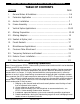
Series 5900 Silicone Structural Glazed Curtain Wall Installation SECTION TABLE OF CONTENTS PAGE I. General Notes & Guidelines …………………………………………….……. 3-4 II. Perimeter Application ………...…….…………………………………….…… 5-6 III. Anchor Installation ………………..………………………………………..….. 7 IV. Frame Assembly .………………….…………………………………………..… 8-9 V. Vertical Splice Applications ……….……………………………….……….. 10-12 VI. Glazing Preparation …………………………………………………………….. 13-14 VII. Glazing Adaptors ………………………………………………………..….…… 15 VIII.
Series 5900 Silicone Structural Glazed Curtain Wall Installation Section I: General Notes & Guidelines I. II. HANDLING / STORING / PROTECTING ALUMINUM - The following precautions are recommended to assure early acceptance of your products and workmanship. A. HANDLE CAREFULLY - Store with adequate separation between components so the material will not rub together. Store material off the ground. Protect materials against weather elements and other construction trades. B.
Series 5900 Silicone Structural Glazed Curtain Wall Installation Section I: General Notes & Guidelines F. Follow EFCO framing installation and glazing instructions. G. Verify contents of all material shipments received upon arrival. Verify quantity and correct finishes. NOTIFY EFCO IMMEDIATELY OF ANY DISCREPANCIES OR DAMAGE, THAT MAY HAVE OCCURRED. H. Throughout these instructions the term “SEALANT” will appear.
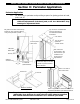
Series 5900 Silicone Structural Glazed Curtain Wall Installation Section II: Perimeter Application Perimeter Application A.) For anchoring to perimeter and providing a spacer for glazing pockets at head, jamb, and sill. Note: Anchoring surfaces of perimeter constructions must be level and plumb within the adjustments of the head, jamb, or sill. See “APPROVED” shop drawings for adjustment limits. Fill gasket race with sealant in top bottom of each vertical mullion to marry with perimeter sealant.
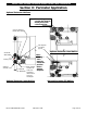
Series 5900 Silicone Structural Glazed Curtain Wall Installation Section II: Perimeter Application Optional Perimeter Mullions Note: The caulking must overlap the metal to metal joint at the critical seal line. Cap seal fastener heads with sealant. Set adaptors in sealant typical. CRITICAL SEAL LINE. Primary seal Optional cosmetic seal Optional Perimeter Head Mullion Note: Setting chair must be rolled into position Miter adaptor before and filler at glazing ½” Nominal vertical to adaptors.
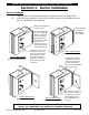
Series 5900 Silicone Structural Glazed Curtain Wall Installation Section III: Anchor Installation Anchor Installation A.) B.) Attach anchors to mullions with temporary alignment screws as shown below. Install the vertical mullions in position and attach anchors to the building structure per the “APPROVED” shop drawings. High impact polystyrene horseshoe shim Weld to building structure per “APPROVED” shop drawings. After final alignment of mullion, align drill mullion in best hole location.
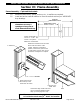
Series 5900 Silicone Structural Glazed Curtain Wall Installation Section IV: Frame Assembly Frame Assembly – Captured Horizontals A.) B.) Assemble shear blocks, splices, anchors, etc., to mullions as required. Install and anchor vertical mullions to form the vertical sections per “APPROVED” shop drawings OVERALL DIMENSION CHECK Note: Check overall frame dimensions on every 5 openings on long runs to avoid dimensional build-up. * DIMENSION CHECK EVERY 5 UNITS Interior horizontals are cut D.L.O. – 1/32”.
Series 5900 Silicone Structural Glazed Curtain Wall Installation Section IV: Frame Assembly Frame Assembly – Silicone Structural Glazed Horizontals A.) B.) Assemble shear blocks, splices, anchors, etc., to mullions as required. Install and anchor vertical mullions to form the vertical sections per “APPROVED” shop drawings. Rotate the horizontal over the shear block from the interior of the system.
Series 5900 Silicone Structural Glazed Curtain Wall Installation V: Vertical Splice Applications Vertical Splice Joints Space vertical mullion expansion joints per “APPROVED” shop drawings and in conjunction with SSG splice locations. B.) Keep in mind that spacing may vary with job site temperature. On multiple stacked applications, key horizontals must be installed to establish grades regardless of expansion joint dimension. C.) Splice joints should occur at spandrel areas. D.
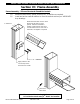
Series 5900 Silicone Structural Glazed Curtain Wall Installation V: Vertical Splice Applications Vertical Splice Joints at SSG Verticals and Captured Horizontals Splice should occur at the spandrel areas. B.) Fabrication Note: Match drill the splice for shear block attachment. C.) Splice Note: The vertical mullions that are structurally glazed must be spliced at the horizontal locations. (All mullion splice locations must be reviewed by a factory engineer.) 2 1/2" A.
Series 5900 Silicone Structural Glazed Curtain Wall Installation V: Vertical Splice Applications Vertical Splice Joints at SSG Verticals and Horizontals A.) Splice should occur at the spandrel areas. B.) Fabrication Note: Match drill the splice for shear block attachment. 2 1/2" C.) Splice Note: The vertical mullions that are structurally glazed must be spliced at the horizontal locations. (All mullion splice locations must be reviewed by a factory engineer.
Series 5900 Silicone Structural Glazed Curtain Wall Installation VI: Glazing Preparation Glazing Preparation at Structural Glazed Mullions Note: All thermal isolators should be removed from the reels and allowed to shrink prior to installation. Prior to installing the mullion plugs, seal all three sides of the pocket, making sure all cavities are filled. Install thermal isolator prior to installing the mullion plugs.
Series 5900 Silicone Structural Glazed Curtain Wall Installation VI: Glazing Preparation Glazing Preparation At Captured Mullions A.) Install the thermal isolator in the vertical mullion, run continuously, and butt joint as required. B.) Seal vertical mullion raceway 1” long prior to the installation of the joint plugs. C.) Place and seal the joint plug. D.) Tool off all excess sealant. E.) Apply sealant to the face of the joint plug prior to installation of the pressure plate. See page #19.
Series 5900 Silicone Structural Glazed Curtain Wall Installation VII: Glazing Adaptors Installation of Glazing Adaptors at Silicone Structural Glazed Mullions A.) Vertical adaptor length without a mullion expansion joint equal D.L.O. plus 1”. B.) Vertical adaptor length with a mullion expansion joint, see the “APPROVED” shop drawings. C.) Horizontal adaptor length equal D.L.O. minus 1/16”. D.) Install the vertical adaptors first, and attach with #8 X 1 ¼” PLPH SMS at a minimum of 18” on center.
Series 5900 Silicone Structural Glazed Curtain Wall Installation VIII: Sealant At Splice Joint Installation of Backer Rods at Structurally Glazed Mullion Splices Closed cell sponge joint plug Expansion joint Splice sleeve Note: At corner mullions, use more than one backer rod as required, and miter it to fit the corner joint. Install backer rod foam at expansion joint.
Series 5900 Silicone Structural Glazed Curtain Wall Installation IX: Preset Gaskets Apply Preset Glazing Gaskets to Mullions A.) Apply sealant into gasket race a minimum of 2” each direction at each corner. B.) Remove glazing gaskets from the reel and allow to shrink. C.) Cut vertical gaskets D.L.O. plus 1 ¾”. D.) Cut horizontal gaskets D.L.O. plus ½”. E.) Seal all gasket corners: Pull horizontal gaskets back, seal end, and compress into the vertical gasket to insure a snug fit.
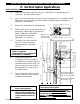
Series 5900 Silicone Structural Glazed Curtain Wall Installation X: Miscellaneous Applications Clean A.) Clean all metal and infill surfaces that will come in contact with the structural silicone sealant with the proper cleaner. B.) Apply silicone primer as recommended by the silicone manufacturer. Setting Blocks A.) Position and install the setting blocks per the “APPROVED” shop drawings. Position Glazing Infill A.
Series 5900 Silicone Structural Glazed Curtain Wall Installation XI: Pressure Plate Attachment Pressure Plate Attachment A.) Attach pressure plates with ¼” X 1” stainless steel hex washer head pressure plate screws. Typical spacing is 6” on center. B.) Torque all pressure plate screws to 80 inch pounds. In cold weather, first torque all screws to 40 inch pounds. When possible, work from the center outward on horizontal and from sill upward on verticals.
Series 5900 Silicone Structural Glazed Curtain Wall Installation XI: Pressure Plate Attachment CL MULL Pressure Plate Attachment 2 1/2" 4" TYPICAL 1/4" Weep slots Seal joints with sealant Note: Reference pages 11 through 13 for recommended pressure plates at splice locations. Install the first screw approximately 3” from the end. Typical screw spacing is 6” on center.
Series 5900 Silicone Structural Glazed Curtain Wall Installation XII: Temporary Retainers and Sealant Temporary Retainers A.) B.) Temporary retainers are supplied by EFCO based on the lineal footage of structural glazed members divided by 2. The location of the temporary exterior infill retainers should not exceed a maximum of 24”* on center. *(If high wind conditions are anticipated, additional retainers may be required.
Series 5900 Silicone Structural Glazed Curtain Wall Installation Section XIII: Exterior Cover Installation Snap-On Exterior Covers A.) Set vertical covers as shown on “APPROVED” shop drawings. 7/16" Drill 5/16” diameter weep holes in the horizontal covers 2” from each end. Note: Care must be taken to avoid damage to the covers during installation. Use a nominal 12” long 2 X 4 and mallet or hammer to seat the cover. Approx. 12” long wood block Mallet or hammer B.) C.) D.) E.
Series 5900 Silicone Structural Glazed Curtain Wall Installation Section XIV: Steel Reinforcement Steel Reinforcement A.) At large spans or in high wind load areas, steel reinforcement may be necessary. B.) Reinforcement requirements will vary on a per job basis. C.) Reference the “APPROVED” shop drawings for steel requirements and locations. D.) When steel reinforcement is factory installed in the mullions, use fasteners to prevent damage or slippage of the steel during shipping.