Series T200 / t300 Tie rod door Installation Instructions Part NO.
TABLE OF CONTENTS PAGE 1 SECTION I II III IV V VI VII VIII IX X XI XII XIII XIV GENERAL NOTES AND GUIDELINES DOOR PACKAGE IDENTIFICATION PARTS IDENTIFICATION OFFSET JACK SCREW ASSEMBLY TIE ROD CUT LENGTH TIE ROD ASSEMBLY GLAZING AND REGLAZING DOORS PUSH/PULL ASSEMBLY OFFSET PIVOT APPLICATION BUTT HINGE APPLICATION HEADER PREPARATION FOR C.O.C.
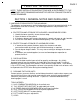
PAGE 2 T200/T300 TIE ROD DOOR NOTE: THESE INSTALLATION INSTRUCTIONS ARE A SUPPLEMENT TO THE APPROVED SHOP DRAWINGS AND MUST BE USED IN CONJUNCTION WITH THOSE DRAWINGS. SECTION I: GENERAL NOTES AND GUIDELINES I. HANDLING-STORING-PROTECTING ALUMINUM Tie rod doors and components are finished products that must be protected while in the packing boxes and after assembly. The following procedures and precautions are recommended. A. PROTECTION AND STORAGE OF PACKAGED, UNASSEMBLED DOORS 1.
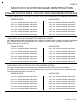
PAGE 3 SECTION II: DOOR PACKAGE IDENTIFICATION AVAILABLE DOOR SIZES, COLORS, AND HARDWARE PACKAGES BLANK T200 DOORS: INCLUDES 1/4" GLASS STOPS (NO HARDWARE OR HARDWARE PREPARATION) SINGLE DOORS: PAIR DOORS: 3’0" X 7’0" CLEAR, BRONZE, OR BLACK 6’0" X 7’0" CLEAR, BRONZE, OR BLACK 3’6" X 7’0" CLEAR, BRONZE, OR BLACK 7’0" X 7’0" CLEAR, BRONZE, OR BLACK 4’0" X 7’0" CLEAR, BRONZE, OR BLACK 8’0" X 7’0" CLEAR, BRONZE, OR BLACK 3’0" X 8’0" CLEAR, BRONZE, OR BLACK 6’0" X 8’0" CLEAR, BRONZE, OR BLACK 3’6" X
PAGE 4 SECTION II: DOOR PACKAGE IDENTIFICATION (CONTINUED) T200 DOORS WITH BUTT HINGES FOR CONCEALED OVERHEAD CLOSER: INCLUDES MAXIMUM SECURITY DEAD LOCK, INTERIOR THUMB TURN CYLINDER, EXTERIOR CYLINDER, BUTT HINGES, EFCO EXTRUDED PUSH/PULLS, AND 1/4" GLASS STOPS.
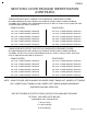
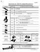
PAGE 5 SECTION III: PARTS IDENTIFICATION DETAIL PART # DESCRIPTION/ PARTS IN PACKAGE M120 M151 36" TIE ROD 48" TIE ROD IQT1 3/8"-16 SERRATED LOCK NUT FS75 TIE ROD WASHER (TR200 ONLY) OFFSET JACK SCREW ASSEMBLY PART # STILE K421 T200 HB17 - OFFSET JACK SCREW BLOCK WM62 - FOAM SPRING BLOCK IHP2 - OFFSET JACK SCREW 1/4"-20 X 3/4" HX-MS K432 T300 HB17 - OFFSET JACK SCREW BLOCK WM62 - FOAM SPRING BLOCK M103 - OFFSET JACK SCREW 1/4"-20 X 2" HX-MS # / DESCRIPTION HB18 1/4" OFFSET JACK SCREW CA
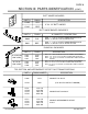
PAGE 6 SECTION III: PARTS IDENTIFICATION (CONT.) BUTT HINGE PACKAGES PART # FINISH HY90 CLR. DESCRIPTION 4" X 4 1/2" BUTT HINGES HY92 BRZ. BUTT HINGE BACKER PACKAGES # / QUANTITY / DESCRIPTION PART # FINISH K900 CLR. F528 - 1 - 4" X 4 1/2" BUTT HINGE BACKER PLATE M100 - 4 - #12-24 X 3/4" PH-FH-MS 18-8 K901 BRZ. F528 - 1 - 4" X 4 1/2" BUTT HINGE BACKER PLATE M108 - 4 - #12-24 X 3/4" PL-FH-MS 18-8 OX PUSH/PULL PACKAGES PART # FINISH 36" & BELOW LEAF SIZES K415 K416 K417 CLR. BRZ. BLK.
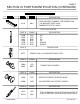
PAGE 7 SECTION III: PARTS IDENTIFICATION (CONTINUED) DESCRIPTION K110 MILL LOCK SUPPORT CHANNEL FOR REGENT 2333 1 1/8" BACKSET DEAD LOCK (T300 BEVELED STILE ONLY) LOCK FACE PLATES PART # FINISH HZ80 HZ82 HZ81 HZ83 HZ78 HZ79 CLR. CLR. BRZ. BRZ. CLR. BRZ. PART # HZ77 TIE ROD DOORS DESCRIPTION RH LH RH LH RADIUS RADIUS DESCRIPTION REGENT 2333 1 1/8" BACKSET DEAD LOCK PART # FINISH DESCRIPTION HZ0N H20P CLR. BRZ. PART # FINISH HZ0L CLR. KEYED DIFFERENT OR KEYED ALIKE HZ0M BRZ.
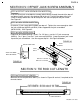
PAGE 8 SECTION IV: OFFSET JACK SCREW ASSEMBLY STEP #1 OFFSET JACK SCREW BLOCK INSERTION Insert the offset jack screw block assembly (#K421/K432) through the end of the top rail and down into the slot cut in the glazing side of the rail. Position the edge of the jack screw assembly toward the side of the top rail with the hole prep for the jack screw. See Figure #1. STEP #2 JACK SCREW INSERTION Insert one (1) jack screw (#IHP2/M103) per top rail.
PAGE 9 SECTION VI: TIE ROD ASSEMBLY STEP #5 TOP AND BOTTOM RAIL ADAPTOR INSERTION Slide the top rail adaptors (#FS76) into the vertical stiles and center the hole in the adaptors over the top hole in the door stiles, as shown in Figure #4. Note: Position the bottom rail adaptors by aligning the bottom hole of the adaptor with the hole in the bottom of the stile, as shown in figure #5. STEP #6 TIE ROD AND RAIL ASSEMBLY Insert the tie rod (#M120 or #M150) through the adaptor and door stile.
PAGE 10 SECTION VII: GLAZING AND REGLAZING DOORS STEP #7 SETTING BLOCKS APPLICATION Insert three (3) setting blocks (#H348 or #H159) at approximately 6" from the inside corners. Setting blocks are used at the door stiles and the bottom rail only. An adjustable jack screw will be used at the top rail. Refer to Figure #1 on page 8. If required, apply silicone to the back of the setting blocks to keep them in the correct position until the glass is installed. See Figure #8.
SECTION VIII: PUSH/PULL ASSEMBLY PAGE 11 STEP #10 PUSH BAR END CAPS If required, cut the push bar to length. The push bar must be cut from the hinge end. Consult the chart below for the correct cut length formula. Insert the push bar end caps into the ends of the push bar as shown in Figure #10. Note: To ensure a tight fit, EFCO recommends applying a thin coat of two part epoxy to the legs of the end caps prior to being inserted into the push bar. See Figure #10.
PAGE 12 SECTION IX: OFFSET PIVOT APPLICATION STEP #15 SETTING THE DOOR INTO THE FRAME The top pivot will be attached to the door stile and requires no adjustment after the door has been set into the frame. All adjustments to the door are by the intermediate offset pivot if used, and the bottom offset pivot. To set the door, depress the top pivot pin and hold down with your index finger. Place the door portion of the bottom pivot onto the frame portion of the bottom pivot.
PAGE 13 SECTION IX: OFFSET PIVOT APPLICATION (CONT.) STEP #16 SETTING THE DOOR INTO THE FRAME Use a flat tipped screwdriver to remove the cap from the bottom of the intermediate offset pivot. Turn the pivot pin counterclockwise to lower the pin. After the pin has been retracted, rotate the door open to 90˚ and set the door on the bottom pivot. Then, raise the pivot pin on the intermediate pivot by turning the pivot pin clockwise. See Figure #13.
PAGE 14 SECTION IX: OFFSET PIVOT APPLICATION (CONT.) STEP #17 BOTTOM OFFSET PIVOT Attach the bottom offset pivot frame portion to the bottom of the jamb using three (3) #12-24-1/4" F.H.M.S., and attach the threshold to the bottom pivot with two (2) #12-24 x 1/4" PL-FH-MS. Adjust the door clearance by turning the pin clockwise to lower the door, and counterclockwise to raise the door. After the proper door clearances are reached, tighten the set screw on the pivot with a 3/32" Allen wrench. See Figure #14.
PAGE 15 SECTION XI: HEADER PREPARATION FOR C.O.C. STEP #19 HEADER PREPARATION For C.O.C. header preps, see chart below for dimensions based on application. 1. DIMENSION ’A’, face of jamb to center line of spindle must be maintained. 2. DIMENSION ’B’, pivot or hinge side of header to center line of spindle regardless of header width. See Figure #16. STEP #20 C.O.C. INSTALLATION 1. Install the closer in the prepared header. 2.
PAGE 16 SECTION XIII: CLEARANCE ADJUSTMENTS STEP #22 MINOR CLEARANCE ADJUSTMENT Open and support the door with a wedge. Use the wedge to raise the door to the desired position. With a 7/16" socket and ratchet, turn the jack screw clockwise until pressure is applied to the glass. To lower the corner, turn the jack screw counterclockwise. Readjust the wedge and tighten the jack screw until pressure is applied to the glass. The door can be adjusted again, if required. See Figure #18.
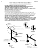
PAGE 17 SECTION XIV: TIE ROD DOOR CUT LENGTH ALTERATIONS STEP #23 LOCK STILE LENGTH ALTERATIONS The minimum cutoff for the lock stile is 9/16" as shown in Figure #19. The minimum cutoff needs to be taken from the top of the lock stile only. This will prevent having to relocate the M.S. lock. STEP #24 HINGED STILE LENGTH ALTERATIONS The minimum cutoff for the hinged stile is 9/16" as shown in Figure #20. When using a C.O.C., the cutoff must be taken from the bottom of the hinged stile only.