SpeedStreamª Router Family Command Line Interface Guide
January 2000 Copyright Efficient Networks provides this publication Òas isÓ without warranty of any kind, either expressed or implied, including, but not limited to, the implied warranties of merchantability or fitness for a particular purpose. All rights reserved. No part of this book may be reproduced in any form or by any means without written permission from Efficient Networks. Changes are periodically made to the information in this book. They will be incorporated in subsequent editions.
WhatÕs New in Release 4? This version of the Command Line Interface (CLI) manual has been updated to document features available with Release 4 of the kernel software. The following list directs you to the CLI documentation for these new features: See page 18 to read about: Telephony Services ¥ A Voice over DSL (VoDSL) router allows delivery of both telephony (voice) and data services over a single DSL line.
¥ Clear command to reset filter counters. ¥ Watch message control via -q (quiet) and -v (verbose) parameters. See page 99 to read about: Software Option Keys ¥ New command to enter a software option key See page 176 and page 203 to read about: Setting a Management Address ¥ Assignment of an IP address for management use only See page 293 to read about: Debugging Commands ¥ 4 Debugging commands should be used with caution because they are not fully supported.
About This Guide The Command Line Interface guide contains information on the syntax and use of the Command Line Interface for the family of DSL routers. It provides the steps and information needed to configure the router software and troubleshoot problems using the Command Line Interface. Configuration of network connections, bridging, routing, and security features are essentially the same for all DSL routers, unless otherwise noted.
References User Guide. Contains an overview of the routerÕs software and hardware features and details on hardware installation and software configuration using the Windows-based Configuration Manager. Quick Start Guide. Describes the configuration process involved in setting up a specific router model.
Table of Contents WhatÕs New in Release 4? . . . . . . . . . . . . . . . . . . . . . . . . . . . . . . . . . . . . . . . . . . . . . . . . . . . . . . . . . . . .3 About This Guide. . . . . . . . . . . . . . . . . . . . . . . . . . . . . . . . . . . . . . . . . . . . . . . . . . . . . . . . . . . . . . . . . . .5 How This Guide is Organized. . . . . . . . . . . . . . . . . . . . . . . . . . . . . . . . . . . . . . . . . . . . . . . . . . . . .5 References . . . . . . . . . . . . . . . . . . . . . . . . . .
Configuring RFC 1483 / RFC 1490 with IP Routing . . . . . . . . . . . . . . . . . . . . . . . . . . . . . . . . . . 50 Configuring RFC 1483 / RFC 1490 with IPX Routing . . . . . . . . . . . . . . . . . . . . . . . . . . . . . . . . 51 Configuring RFC 1483 / RFC 1490 with Bridging . . . . . . . . . . . . . . . . . . . . . . . . . . . . . . . . . . . 52 Configuring MAC Encapsulated Routing: RFC 1483MER / RFC 1490MER with IP Routing . 53 Configuring FRF8 with IP Routing . . . . . . . . . . . . . . . . . . . .
Filter Actions. . . . . . . . . . . . . . . . . . . . . . . . . . . . . . . . . . . . . . . . . . . . . . . . . . . . . . . . . . . . . . . .104 IP Filter Commands . . . . . . . . . . . . . . . . . . . . . . . . . . . . . . . . . . . . . . . . . . . . . . . . . . . . . . . . . .105 Special Notes. . . . . . . . . . . . . . . . . . . . . . . . . . . . . . . . . . . . . . . . . . . . . . . . . . . . . . . . . . . . . . . .105 L2TP Tunneling Ñ Virtual Dial-Up . . . . . . . . . . . . . . . . . . . . . . . . . .
Manual Boot Menu . . . . . . . . . . . . . . . . . . . . . . . . . . . . . . . . . . . . . . . . . . . . . . . . . . . . . . . . . . . 269 Identifying Fatal Boot Failures . . . . . . . . . . . . . . . . . . . . . . . . . . . . . . . . . . . . . . . . . . . . . . . . . . 273 Software Kernel Upgrades . . . . . . . . . . . . . . . . . . . . . . . . . . . . . . . . . . . . . . . . . . . . . . . . . . . . . . . . . 273 Booting and Upgrading from the LAN. . . . . . . . . . . . . . . . . . . . . . . . . . . . . .
IPX Routing Concepts . . . . . . . . . . . . . . . . . . . . . . . . . . . . . . . . . . . . . . . . . . . . . . . . . . . . . . . . . . . . .309 Configure IPX Routing . . . . . . . . . . . . . . . . . . . . . . . . . . . . . . . . . . . . . . . . . . . . . . . . . . . . . . . . . . . .309 Step 1: Collect Your Network Information for the Target (Local) Router . . . . . . . . . . . . . . . . .310 Step 2: Review your Settings . . . . . . . . . . . . . . . . . . . . . . . . . . . . . . . . . . . . . . . . . .
Introduction This manual describes the Command Line Interface for your router. The Command Line Interface gives you access to all the capabilities of your router. Many of the router configuration capabilities are also available through an easy-to-use, point-and-click graphic interface.Your router supports use of the Microsoft¨ Windowsª-based ConÞguration Manager, Quick Start, and/ or Web-based GUI programs. To learn how to access those programs, see the documentation that came with the router.
Introduction
Chapter 1. Router Concepts This chapter provides background information applicable to the router on topics useful to network administrators.
Numerous network protocols have evolved, and within each protocol are associated protocols for routing, error handling, network management, etc. The following chart displays the networking and associated protocols supported by the router.
IP/IPX Routing On Bridging to/from Remote Router Off Data packets carried IP (TCP, UDP), IPX Operational characteristics Basic IP, IPX connectivity Typical usage When only IP/IPX trafÞc is to be routed and all other trafÞc is to be ignored. For IP, used for Internet access. Note: This is the most easily controlled configuration. IP/IPX Routing On Bridging to/from Remote Router On Data packets carried IP/IPX routed; all other packets bridged.
¥ Routing is performed to all remote routers entered into the remote router database. All routing can be enabled or disabled with a system-wide control. Operation of the router is influenced by routing and bridging controls and filters set during router configuration as well as automatic spoofing and filtering performed by the router. For example, general IP or IPX routing, and routing or bridging from specific remote routers are controls set during the configuration process.
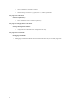
Phone system Ethernet Phone lines Voice Gateway DSLAM Voice over DSL Router DSL Line Class 5 Switch PSTN ATM/Frame Network Router Internet LAN Configuring Your Telephony Services Router models are available to support telephony services over both ATM and Frame Relay networks. For telephony over ATM, the VPI/VCI is automatically set (to 0*39 for most routers). For telephony over Frame Relay, the DLCI is automatically set to 22. The value must match your service providerÕs value.
PAP/CHAP Security Authentication The router supports PAP (Password Authentication Protocol) and CHAP (Challenge Handshake Authentication Protocol) under PPP. Security authentication may not be required due to the nature of the connection in a DSL environment (traffic occurs on a dedicated line/virtual circuit. However, authentication may be specifically required by the remote end, the ISP, or the NSP. When authentication is not required, security can be disabled with the command remote disauthen (page 190).
Authentication Process The authentication process occurs regardless of whether a remote router connects to the local router or vice versa, and even if the remote end does not request authentication. It is a bi-directional process, where each end can authenticate the other using the protocol of its choice (provided the other end supports it). During link negotiation (LCP), each side of the link negotiates which protocol to use for authentication during the connection.
router. This allows you to set a unique CHAP or PAP authentication password for authentication of the local site by the remote site only when the router connects to that remote site. A common use is for the system override password is to set a password assigned to you by Internet Service Providers (ISPs). Similarly, the system name of the local router can be overridden for connecting to a specific remote with the command remote setOurSysName (page 204).
Interoperability Between the Router and Other Equipment The router uses industry-wide standards to ensure compatibility with routers and equipment from other vendors. To interoperate, the router supports standard protocols on the physical level, data link level for frame type or encapsulation method, and network level. For two systems to communicate directly, they must use the same protocol at each level. Most protocols do not support negotiable options, except for PPP.
¥ ¥ ¥ ¥ ¥ ¥ ¥ ¥ ¥ ¥ ¥ ¥ ¥ ¥ ¥ ¥ ¥ ¥ ¥ ¥ ¥ ¥ ¥ ¥ RFC 1877 RFC 1962 RFC 1969 RFC 1973 RFC 1974 RFC 1990 RFC 1994 RFC 2104 RFC 2131 RFC 2132 RFC 2364 RFC 2419 RFC 2401 RFC 2402 RFC 2403 RFC 2404 RFC 2405 RFC 2406 RFC 2407 RFC 2408 RFC 2409 RFC 2410 RFC 2412 RFC 2451 Automatic IP / DNS PPP Compression Control Protocol (CCP) DES PPP in Frame Relay Stac LZS compression protocol Multi-Link Protocol (MLP) User Authentication PAP / CHAP Dynamic Host Configuration Protocol (DHCP) DHCP Client PPP over ATM DES v2 Sec
0x0021 IP 0x002d Van Jacobson compressed TCP/IP 0x002f Van Jacobson uncompressed TCP/IP 0x8031 Bridge NCP 0x0031 Bridge Frame The command for this encapsulation option is: remote setProtocol PPP See page 204. Note: With PPP over ATM, the address and control fields (i.e., FF03) are never present; this also is the case for LCP packets.
MAC Encapsulated Routing: RFC 1483MER (ATM) or RFC 1490MER (Frame Relay) MER encapsulation allows IP packets to be carried as bridged frames, but does not prevent bridged frames from being sent as well, in their normal encapsulation format: RFC 1483 (ATM) or RFC 1490 (Frame Relay). If IP routing is enabled, then IP packets are prepended with the sequence 0xAAAA0300 0x80c20007 0x0000 and sent as bridged frames. If IP routing is not enabled, then the packets appear as bridged frames.
L2TP Tunneling Database ATOM.DAT SDSL.DAT DMT.DAT IPSEC.DAT IKE.DAT AUTOEXEC.BAT : Autoexec file of commands to run on next reboot. AUTOEXEC.OLD: Autoexec file that has run already Note: Users should not delete any of these files, unless advised by Tech Support. Any file contained within the system may be retrieved or replaced using the TFTP protocol. Specifically, configuration files and the operating system upgrades can be updated.
Chapter 1.
Chapter 2. Planning for Router ConÞguration This chapter describes the terminology and the information that you need to obtain before configuring the router. The information needed to configure the router is contingent on the chosen Link Protocol. It is therefore important to know which Link Protocol you are using (this is determined by your Network Service Provider) so that you can refer to the configuration sections that apply to your setup.
Essential ConÞguration Information This section describes the configuration information associated with each Link Protocol/Network Protocol combination and also provides configuration information for the Dual-Ethernet router. If you are using Link and Network Protocols: 1. Determine which Link Protocol/Network Protocol association you are using from your Network Service Provider (NSP). 2.
PPP Link Protocol (over ATM or Frame Relay) The PPP Link Protocol is an encapsulation method that can be used over ATM (for ATM routers) or Frame Relay (for Frame-Relay routers) Combined with the IP, IPX, or Bridging Network Protocols, PPP over ATM and PPP over Frame Relay share the same configuration characteristics, except for the connection identifiers: VPI/VCI numbers are used for ATM, and a DLCI number is used for Frame Relay.
¥ DNS Internet Account Information (optional) This information is obtained from your Network Service Provider. Consult with you Network Service Provider to find out if you need to enter the following information: ¥ ¥ DNS server address ¥ DNS second server address ¥ DNS domain name IP Routing Addresses For the Ethernet Interface This information is defined by the user or your Network Administrator.
IPX Routing Network Protocol ¥ System Names and Authentication Passwords For the Target Router This information is defined by the user. You must choose a name and authentication password for the target router. They are used by a remote router to authenticate the target router. For the Remote Site(s) This information is obtained from the Network Service Provider. For each remote site, you must have the site name and its authentication password.
Internal Network Number It is a logical network number that identifies an individual Novell server. It is needed to specify a route to the services (i.e., file services, print services) that Novell offers. It must be a unique number. External Network (a.k.a. IPX Network Number) It refers to a physical LAN/wire network segment to which servers, routers, and PCs are connected (Ethernet cable-to-router segment). It must be a unique number.
Bridging Network Protocol ¥ System Names and Authentication Passwords For the Target Router This information is defined by the user. You must choose a name and authentication password for the target router. They are used by a remote router to authenticate the target router. ¥ For the Remote Site(s) This information is obtained from the Network Service Provider. For each remote site, you must have the site name and its authentication password.
RFC 1483/RFC 1490 Link Protocols The Link Protocol RFC 1483 is a multiprotocol encapsulation method over ATM and is used by ATM routers. RFC 1490 is a multiprotocol encapsulation method over Frame-Relay and is used by Frame-Relay routers. RFC 1483 and RFC 1490 combined with the IP, IPX, or Bridging Network Protocols share the same configuration characteristics, except for the connection identifiers: VPI/VCI numbers are used for RFC 1483 and a DLCI number is used for RFC 1490.
TCP/IP Ethernet Routes You normally do not need to define an Ethernet IP route. An Ethernet IP route consists of an IP address, a mask, a metric, and a gateway. An Ethernet route is usually defined when there are multiple routers on the Ethernet that cannot exchange routing information. For the WAN Interface This information is obtained from the Network Administrator.
Internal Network Number This is a logical network number that identifies an individual Novell server. It is needed to specify a route to the services (i.e., file services, print services) that Novell offers. It must be a unique number. External Network (a.k.a. IPX Network Number) This number refers to a physical LAN/wire network segment to which servers, routers, and PCs are connected (Ethernet cable-to-router segment). It must be a unique number.
¥ DNS Internet Account Information (optional) This information is obtained from the Network Service Provider. Consult with your Network Service Provider to find out if you need to enter the following information: ¥ DNS server address ¥ DNS second server address ¥ DNS domain name MAC Encapsulated Routing MAC Encapsulated Routing (MER) allows IP packets to be carried as bridged frames (bridged format).
¥ DNS second server address ¥ DNS domain name Note: If you intend to only connect to the Internet, enter this information using the Internet Quick Start configurator. ¥ IP Routing Entries For the Ethernet Interface This information is defined by the user or the Network Administrator. Ethernet IP Address (Local LAN) An Ethernet LAN IP address and subnet mask are required for the routerÕs local Ethernet LAN connection. TCP/IP Ethernet Routes You normally do not need to define an Ethernet IP route.
FRF8 Link Protocol The FRF8 Link Protocol is an encapsulation method that allows an ATM router to interoperate with a Frame- Relay network. FRF8 is only used in conjunction with the IP Network Protocol. Obtain the information described below. This data will be used later to configure your router using the Command Line Interface (see Configuration Tables, on page 45). IP Routing Network Protocol ¥ VPI and VCI Numbers Your router may have been preconfigured with VPI/VCI numbers.
For the ATM WAN Interface This information is obtained from the Network Administrator or the Network Service Provider. Source (Target/Local) WAN Port Address and Mask You must specify a Source WAN IP address for the WAN connection to the remote router (whether or not Network Address Translation is enabled. The Source WAN address is the address of the local router on the remote network. The mask is the mask used on the remote network. Check with your system administrator for details.
Configuring the Dual-Ethernet Router for IP Routing The eth commands are used to configure the Dual-Ethernet router for IP routing. Refer to the section DualEthernet Router Commands (ETH), on page 213, for usage and syntax information. The last argument of each ETH command determines which interface is being configured (0 for ETH/0, 1 for ETH/1). Each interface (ETH/0 and ETH/1) must be set. A minimum of one route must be defined to have a working configuration.
Chapter 3. ConÞguring Router Software This chapter covers configuration tables and verifying the router configuration. It also provides sample configurations. Configuration commands are outlined for each Link Protocol/Network Protocol supported by the router. The information needed to configure the router is contingent on the chosen Link Protocol.
ConÞguration Tables The following tables give you step-by-step instructions for standard configurations of the following Network Protocol/Link Protocol associations, as well as a configuration table for a Dual-Ethernet Router: ¥ PPP Link Protocol with IP Routing Network Protocol ¥ PPP Link Protocol with IPX Routing Network Protocol ¥ PPP Link Protocol with Bridging Network Protocol ¥ RFC 1483/RFC 1490 Link Protocols with IP Routing Network Protocol ¥ RFC 1483/RFC 1490 Link Protocols with IPX Routin
Configuring PPP with IP Routing This table outlines configuration commands for the PPP Link Protocol with the IP Routing Network Protocol.
Configuring PPP with IPX Routing This table outlines configuration commands for the PPP Link Protocol with the IPX Routing Network Protocol. Note: Appendix B provides step-by-step information on how to configure IPX routing.
Configuring PPP with Bridging This table outlines configuration commands for the PPP Link Protocol with the Bridging Network Protocol.
Configuring PPP over Ethernet (PPPoE) This table outlines configuration commands for the PPP Link Protocol with the Bridging Network Protocol over Ethernet.
Configuring RFC 1483 / RFC 1490 with IP Routing This table outlines configuration commands for the RFC 1483 and the RFC 1490 Link Protocols with the IP Routing Network Protocol.
Configuring RFC 1483 / RFC 1490 with IPX Routing This table outlines configuration commands for the RFC 1483 and RFC 1490 Link Protocols with the IPX Routing Network Protocol. Note: Appendix B provides step-by-step information on how to configure IPX routing.
Configuring RFC 1483 / RFC 1490 with Bridging This table outlines configuration commands for the RFC 1483 and RFC 1490 Link Protocols with the Bridging Network Protocol.
Configuring MAC Encapsulated Routing: RFC 1483MER / RFC 1490MER with IP Routing This table outlines configuration commands for the RFC 1483MER and RFC 1490MER Link Protocols with the IP Routing Network Protocol.
Configuring FRF8 with IP Routing This table outlines configuration commands for the FRF8 Link Protocol with the IP Routing Network Protocol.
Configuring Mixed Network Protocols Several network protocols can be configured concurrently in the same router. The possible combinations are: ¥ ¥ ¥ ¥ Bridging + IP routing Bridging + IPX routing Bridging + IP routing + IPX routing IP routing + IPX routing General configuration rules: ¥ IP (and IPX) routing takes precedence over bridging. ¥ Each network protocol in the combination is individually configured as described in the preceding tables.
Configuring a Dual-Ethernet Router for IP Routing This table outlines commands used to configure a Dual-Ethernet router for IP routing.
Verify the Router ConÞguration Test IP Routing Test IP Routing over the Local Ethernet LAN (from PC) ¥ Use the TCP/IP ping command or a similar method to contact the configured target router specifying the Ethernet LAN IP address. ¥ If you cannot contact the router, verify that the Ethernet IP address and subnet mask are correct and check the cable connections. ¥ Make sure that you have saved and rebooted after setting the IP address. ¥ Check Network TCP/IP properties under Windows 95.
Test IPX Routing One way to test IPX routing is to check for access to servers on the remote LAN. Under Windows, use the NetWare Connections selection provided with NetWare User Tools. Under DOS, use the command pconsole or type login on the login drive (usually F:). Select the printer server and verify that the server you have defined is listed. When you attempt to access the server, the router will connect to the remote router using the DSL line.
Sample ConÞgurations Sample Configuration 1: PPP with IP and IPX This configuration example comprises: ¥ A scenario describing the configuration ¥ A diagram showing the configuration of the SOHO router ¥ Tables containing the configuration settings for this example ¥ Several list command outputs that are used to check the information entered for this particular configuration ¥ Information about the names and passwords that are used in this configuration example (required for PPP) Note: Appendix A
Sample Configuration 1: Diagram for Target Router (SOHO) Small Home Office SOHO (Target/Local Router) IPX = 456 0,39 (HQ) SOHO Target Router IP:192.168.254.254 255.255.255.0 Workstation/Server 192.168.254.3 255.255.255.0 PC/Client 192.168.254.2 255.255.255.0 2 Virtual Circuits 0,38 (ISP) DSL / ATM Network PPP/IP 192.168.200.20 IPX WAN = 789 Remote Router HQ 0.0.0.0 255.255.255.255 ISP IP:172.16.0.1 255.255.255.0 PPP/IP and IPX IPX NET = 123 Network Service Provider (ISP) DNS: 192.168.200.
Sample Configuration 1: Tables for Target Router (SOHO) SOHO System Settings ConÞguration Section Item Commands System Settings Name System Name system name SOHO Message Message (optional) system msg ConÞgured_Dec_1998 Authentication Password Authentication Password system password SOHOpasswd Ethernet IP Address Ethernet IP Address and Subnet Mask (default IP eth ip addr 192.168.254.254 255.255.255.
SOHO Remote Router Database Entry: HQ ConÞguration Section Item Commands Remote Routers New Entry Remote RouterÕs Name remote add HQ Link Protocol Link Protocol remote setProtocol PPP HQ PVC VPI Number/VCI Number remote setPVC 0*39 HQ Security Minimum Authentication (PAP is the default) remote setauthen PAP HQ Remote RouterÕs Password remote setpasswd HQpasswd HQ Bridging Bridging on/off (Bridging is off by default) remote disbridge HQ TCP/IP Route Addresses Remote NetworkÕs IP Addresse
SOHO Remote Router Database Entry: ISP ConÞguration Section Item Commands Remote Routers New Entry Remote RouterÕs Name remote add ISP Link Protocol Link Protocol remote setProtocol PPP ISP PVC VPI Number/VCI Number remote setPVC 0*38 ISP Security Minimum Authentication remote setauthen PAP ISP (PAP is the default) Remote RouterÕs Password remote setpasswd ISPpasswd ISP Bridging Bridging on/off (Bridging is off by default) remote disbridge ISP TCP/IP Route Addresses Remote NetworkÕs IP
Sample Configuration 1: Check the Configuration with the LIST Commands Type the following commands to obtain a list of your configuration. system list GENERAL INFORMATION FOR System started on.................... Authentication override.............. WAN to WAN Forwarding................. BOOTP/DHCP Server address............ Telnet Port.......................... SNMP Port..............................
Total IPX remote routes.............. Total IPX SAPs....................... Bridging enabled..................... Exchange spanning tree with dest... 0 0 no yes dhcp list bootp server ................. none bootp file ................... n/a DOMAINNAMESERVER (6) ......... 192.168.200.1 DOMAINNAME (15) .............. myISP.com WINSSERVER (44) .............. 172.16.0.2 Subnet 192.168.254.0, disabled - other DHCP servers detected When DHCP servers are active . stop Mask ......................... 255.255.255.
Information About Names and Passwords for Sample Configuration 1 In this configuration example, the PPP Link Protocol requires using system names and passwords. ¥ System Passwords SOHO has a system password ÒSOHOpasswd,Ó which is used when SOHO communicates with HQ for authentication by that site and at any time when HQ challenges SOHO. HQ has a system password ÒHQpasswd,Ó which is, likewise, used when HQ communicates with site SOHO for authentication by SOHO and at any time SOHO challenges HQ.
Sample Configuration 2: RFC 1483 with IP and Bridging This configuration example comprises: ¥ A scenario describing this configuration of the router SOHO ¥ A diagram showing the configuration information needed for this example ¥ Tables containing the configuration settings for this example ¥ Several list command outputs that are used to check the information entered for this particular configuration Note 1: Names and passwords are not required with the RFC 1483 Link Protocol.
Sample Configuration 2: Diagram for Target Router SOHO Small Home Office SOHO (Target Router) 0,39 (HQ) SOHO Target Router Workstation/Server 192.168.254.3 255.255.255.0 PC/Client 192.168.254.2 255.255.255.0 IP:192.168.254.254 255.255.255.0 2 Virtual Circuits 0,38 (ISP) DSL / ATM Network RFC 1483 / IP 192.168.200.20 Remote Router HQ 0.0.0.0 255.255.255.255 IP:172.16.0.1 255.255.255.0 ISP RFC 1483 / IP + Bridging Network Service Provider (ISP) DNS: 192.168.200.1 DNS Domain: myISP.
Sample Configuration 2 : Tables for Target Router (SOHO) SOHO System Settings ConÞguration Section Item Commands System Settings Message Message (optional) system msg RFC1483_dec98 Ethernet IP Address Ethernet IP Address and Subnet Mask eth ip addr 192.168.254.254 255.255.255.0 (default IP address) DHCP Settings DNS Domain Name dhcp set valueoption domainname myISP.com DNS Server dhcp set valueoption domainnameserver 192.168.200.1 WINS Server address dhcp set valueoption winsserver 172.16.0.
SOHO Remote Router Database Entry: ISP ConÞguration Section Item Commands Remote Routers New Entry Remote RouterÕs Name remote add ISP Link Protocol Link Protocol remote setProtocol RFC1483 ISP PVC VPI Number/VCI Number remote setPVC 0*38 ISP Bridging Bridging On/Off remote disbridge ISP (Bridging is Off by default) TCP/IP Route Addresses Remote NetworkÕs IP Addresses, Subnet Masks, and Metric remote addiproute 0.0.0.0 255.255.255.
Sample Configuration 2: Check the Configuration with the LIST Commands system list GENERAL INFORMATION FOR System started on.................... Authentication override.............. WAN to WAN Forwarding.................. BOOTP/DHCP Server address............ Telnet Port.......................... SNMP Port.............................. System message: ADSL RFC1483 sample 12/1/1998 at 17:48 NONE yes none default (23) default (161) eth list ETHERNET INFORMATION FOR Hardware MAC address.
Compression Negotiation.............. Source IP address/subnet mask........ Remote IP address/subnet mask........ Send IP RIP to this dest............. Send IP default route if known..... off 192.168.200.20/255.255.255.255 0.0.0.0/0.0.0.0 no no Receive IP RIP from this dest......... .no Receive IP default route by RIP.... no Keep this IP destination private..... yes Total IP remote routes............... 1 0.0.0.0/255.255.255.255/1 IPX network number................... 00000000 Total IPX remote routes.....
Sample Configuration 3: Configuring a Dual-Ethernet Router for IP Routing Scenario: The following example provides a simple sample configuration for a Dual-Ethernet router (eth_router) with IP routing enabled. The routerÕs hub (ETH/0) belongs to the 192.168.254.0 subnet. The routerÕs ETH/1 belongs to the 192.168.253.0 subnet. ETH/0 will route packets to ETH/1 at the address 192.168.253.254. DHCP is enabled for both subnets.
Chapter 3.
Chapter 4. ConÞguring Special Features The features described in this chapter are advanced topics. They are primarily intended for experienced users and network administrators to perform network management and more complex configurations. ¥ Bridge Filtering and IP firewall ¥ IP protocol controls (RIP) ¥ Dynamic Host Configuration Protocol (DHCP) ¥ Network Address Translation (NAT ) ¥ Management security The folowing features can be purchased as software option keys.
Multiple IP Subnets You may configure the router to provide access to multiple IP subnets on the Ethernet network. (This feature does not apply to IPX or bridged traffic.) Each IP subnet is referenced as a logical Ethernet interface. You may define multiple logical interfaces for each physical Ethernet interface (that is, port) in the router. Each logical interface is referenced by its port number and logical interface number (port #:logical#).
Virtual Routing Tables The virtual routing feature allows you to define multiple routing tables. This is also known as IP virtual router support. To define a new routing table, you must specify a name for the routing table and a range of IP source addresses that use that table. The router determines which routing table to use based on the source address in the packet. For example, if the router receives a packet whose source address is 192.168.254.
Bridge Filtering and IP Firewall You can control the flow of packets across the router using bridge filtering. Bridge filtering lets you ÒdenyÓ or ÒallowÓ packets to cross the network based on position and hexadecimal content within the packet. This enables you to restrict or forward messages with a specified address, protocol, or data content. Common uses are to prevent access to remote networks, control unauthorized access to the local network, and limit unnecessary traffic.
Enable/Disable Internet Firewall Filtering The router supports IP Internet Firewall Filtering to prevent unauthorized access to your system and network resources from the Internet. This filter discards packets received from the WAN that have a source IP address recognized as a local LAN address. Caution: This is a simple firewall check; it does not add much security. For more elaborate firewall features, see IP Filtering, page 103.
IP (RIP) Protocol Controls You can configure the router to send and receive RIP packet information, respectively, to and from the remote router. This means that the local site will ÒlearnÓ all about the routes beyond the remote router and the remote router will ÒlearnÓ all about the local siteÕs routes. You may not want this to occur in some cases. For example, if you are connecting to a site outside your company, such as the Internet, you may want to keep knowledge about your local siteÕs routes private.
DHCP (Dynamic Host ConÞguration Protocol) This section describes how to configure DHCP using the Command Line Interface. Configuring DHCP can be a complex process; this section is therefore intended for network managers. For a complete list and explanation of the DHCP commands, see DHCP (Dynamic Host Configuration Protocol) Commands, page 227. Note: Some DHCP values can be set using the Windows Quick Start application, the Windows Configuration Manager, or the web-based EZ Setup application.
DHCP Administration and Configuration The DHCP administration and configuration process is divided into the following parts: ¥ Manipulating subnetworks and explicit client leases ¥ Setting option values ¥ Managing BootP ¥ Defining option types ¥ Configuring BootP/DHCP relays ¥ Other information Note: To save the DHCP conÞguration or changes to ßash memory in the router, remember to use the command dhcp save.
dhcp add To remove a subnetwork, use: dhcp del Note: All client leases associated with this subnetwork are automatically deleted. Example 1: The following command creates a subnetwork 192.168.254.0 with a subnet mask of 255.255.255.0: dhcp add 192.168.254.0 255.255.255.0 Example 2: The following command deletes the subnetwork 192.168.254.0 and deletes all client leases associated with that subnetwork: dhcp del 192.168.254.0 Chapter 4.
¥ Adding Explicit or Dynamic Client Leases Client leases may either be created dynamically or explicitly. Usually client leases are created dynamically when PCs boot and ask for IP addresses. Explicit client leases To add an explicit client lease, a subnetwork must already exist (use dhcp add to add the subnetwork) before the client lease may be added.
¥ 3. If the client and subnetwork lease options are both ÒdefaultÓ, then the server goes up one level (global) and uses the lease time defined at the global level (server). 4. Lease time: The minimum lease time is 1 hour. The global default is 168 hours. Commands The following commands are used by network administrators to control lease time.
Concepts The server returns values for options explicitly requested in the client request. It selects the values to return based on the following algorithm: 1. If the value is defined for the client, then the server returns the requested value for an option. 2. If the value for the option has not been set for the client, then the server returns the value option if it has been defined for the subnetwork. 3.
Commands for Specific Option Values for a Client Lease To set the value for an option associated with a specific client, use: dhcp set valueoption ... To clear the value for an option associated with a specific client, use: dhcp clear valueoption Example: dhcp set valueoption 192.168.254.251 winserver 192.168.254.
Enable/Disable BootP To allow BootP request processing for a particular client/subnet, use the command: dhcp bootp allow | To disallow BootP request processing for a particular client/subnet, type: dhcp bootp disallow | Use BootP to Specify the Boot Server The following commands let the administrator specify the TFTP server (boot server) and boot file name. The administrator should first configure the IP address of the TFTP server and file name (kernel) from which to boot.
Usually users will not need to define their own option types. The list of predefined option types based on RFC 1533 can be shown by typing dhcp list definedoptions. Commands The following commands are available for adding/deleting option types: dhcp add To list option types that are currently defined, use: dhcp list definedoptions...
BootP/DHCP Relays are enabled and disabled using the command: system bootpserver DHCP Information File DHCP information is kept in the file DHCP.DAT, a self-contained file. This file contains all DHCP information including: ¥ the option definitions ¥ the subnetworks that have been added ¥ the client lease information ¥ the option values that have been set This file can be uploaded/downloaded from one router to another. 90 Chapter 4.
Network Address Translation (NAT) The router supports classic NAT (one NAT IP address assigned to one PC IP address) and a NAT technique known as masquerading (one single NAT IP address assigned to many PC IP addresses). General NAT Rules 1. IP routing must be enabled. 2. NAT can be run on a per-remote-router basis. 3. Any number of PCs on the LAN may be going to the same or different remote routers at the same time.
¥ Obtain an IP Address for NAT The IP address (the IP address ÒknownÓ by the remote ISP) used for this type of NAT can be assigned in two ways. The ISP dynamically assigns the IP address. Use the commands: remote setSrcIpAddr 0.0.0.0 0.0.0.0 save The IP address is assigned locally. Use the commands: remote setSrcIpAddr ww.xx.yy.zz 255.255.255.255 save Note: ww.xx.yy.zz is the IP address that the user on the local LAN assigns.
Example 1: Assume that the local LAN network is 192.168.1.0 255.255.255.0. The following commands are typed to enable a Telnet server on the local LAN with the IP address 192.168.1.3, and an FTP server with the IP address 192.168.1.2. remote addServer 192.168.1.3 tcp telnet router1 remote addServer 192.168.1.2 tcp ftp router1 When the local router receives a request from router1 to communicate with the local Telnet server, the local router will send the request to 192.168.1.3.
The following two commands are used to globally enable/disable a local IP address (on your LAN) as the server for that particular protocol. system addServer discard|me tcp|udp ftp|telnet|smtp|snmp|http [[]] system delServer discard|me tcp|udp ftp|telnet|smtp|snmp|http [[]] where first port: this is the first or only port as seen by the remote end.
6. RouterÕs IP address Ñ The local router selects itself (the local router) as the server. Classic NAT With classic NAT, one PC IP address is translated to one NAT IP address. This NAT technique is primarily used to make certain hosts on a private LAN globally visible and give them the ability to remap these IP addresses as well.
¥ Multiple-Host Remapping Entries Users may enter as many host remapping entries as they wish. Example: remote addHostMapping 192.168.207.40 192.168.207.49 10.0.20.11 remoteName remote addHostMapping 192.168.207.93 192.168.207.99 10.0.20.4 remoteName remote addHostMapping 192.168.209.71 192.168.209.80 10.12.14.16 remoteName The above entries create three mappings: 192.168.207.40 through 192.168.207.49 are mapped to 10.0.20.11 through 10.0.20.20 192.168.207.93 through 192.168.207.99 are mapped to 10.0.20.
Controlling Remote Management With the following security control features, the user can control remote management of the router via Telnet, HTTP, Syslog, and/or SNMP. Disabling SNMP stops the Configuration Manager from accessing the router, which in some environments is desirable. Router system event messages can be automatically sent to a Unix Syslog server. The system syslogport and system addsyslogfilter commands control the access and port numbers.
To delete client ranges previously defined, use these commands: system deltelnetfilter [] | LAN system delsnmpfilter [] | LAN system delhttpfilter [] | LAN system delsyslogfilter [] | LAN To list the range of allowed clients, use the command: system list Restricting Remote Access To allow remote management while making it more difficult for non-authorized persons to access the router, you
Software Option Keys This router has several optional software features that can be purchased as software option keys when ordering the router. These optional features are: ¥ IP routing ¥ DES or 3DES encryption (see Encryption, page 100) ¥ IP filters (see IP Filtering, page 103) ¥ L2TP tunneling (see L2TP Tunneling Ñ Virtual Dial-Up, page 106) ¥ IPSec (see IPSec (Internet Protocol Security), page 119) These options are usually ordered with the router.
Encryption Note: Encryption is a software option. The following section applies only for routers with this option. For routers shipped with the following encryption options, two variants of encrypted data links over PPP have been implemented: ¥ PPP DES (Data Encryption Standard) (RFC1969) ¥ Diffie-Hellman Encryption requires PPP. Caution: PPP DES and Diffie-Hellman encryption options may not be exported outside the United States or Canada.
Use this sample configuration with the additional encryption commands as a guideline to configure your own routers.
remote setEncryption DESE_1_KEY dh96.num SOHO save reboot File Format for the Diffie-Hellman Number File The file consists of 192 bytes, in binary format. There are two 96-byte numbers stored, with the most significant byte in the first position. For example, the number 0x12345678 would appear as 000000...0012345678. The first 96 bytes form the modulus. In the equation x' = g^x mod n, n is the modulus. According to Diffie and Hellman, the modulus should be prime, and (n-1)/2 should also be prime.
IP Filtering IP Filtering is a type of firewall used to control network traffic. The process involves filtering packets received from one interface and deciding whether to route them to another interface or discard them. When it is filtering packets, the router examines information such as the source and destination address contained in the IP packet, the type of connection, etc.
If NAT translation is enabled for the Input interface, NAT translation is performed. Forward Phase At this stage, the router uses its routing table to determine to which interface or link the packet is sent . It then applies the Forward filters based on the Input interface information. Next the router applies the Forward filters based on the Output interface information. Output Phase If NAT translation is enabled for the Output interface, then NAT translation is performed.
action is for packets coming from the local protected network; it passes the packet to IPSec so it can be encrypted and sent to the other IPSec gateway. Although filters are the mechanism by which packets are passed to IPSec, it is recommended that you use IKE, rather than your own filters, to manage your IP Security (see IPSec (Internet Protocol Security), page 119). IP Filter Commands To define and manage IP filters on an Ethernet interface, use the command eth ip filter.
L2TP Tunneling Ñ Virtual Dial-Up This section has four parts: ¥ The Introduction provides a general overview of L2TP tunneling. ¥ The L2TP Concepts section explains LNS, L2TP client, LAC, dial user, tunnels, and sessions. ¥ Configuration describes preliminary configuration steps and verification steps and lists commands associated with the configuration of L2TP and PPP sessions.
LNS, L2TP Client, LAC, and Dial User An L2TP tunnel is created between an L2TP client and LNS. The L2TP client and LNS control the tunnel using the L2TP protocol. Since routers are more often configured as L2TP clients or LNS than as LACs, this section, therefore, emphasizes L2TP client- and LNS-related information. ¥ LNS (L2TP Network Server) The LNS is the point where the call is actually managed and terminated (e.g., within a corporate network).
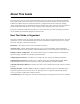
Figure 1 Company Remote User Logical Link PPP session running over the tunnel PC L2TP Client: Dial User+LAC (ISDN router) LNS Router TUNNEL Physical Link Company LAN/server Physical Link IP traffic to the Internet PPP session ISDN line DSL/ATM traffic INTERNET LNS and L2TP Client Relationship The LNS acts as the supervising system. The L2TP client acts both as the dial user and the LAC. One end of the tunnel terminates at the L2TP client. The other end of the tunnel terminates at the LNS.
Sessions Sessions can be thought of as switched virtual circuit ÒcallsÓ carried within a tunnel and can only exist within tunnels. One session carries one ÒcallÓ. This ÒcallÓ is one PPP session. Multiple sessions can exist within a tunnel. The following briefly discusses how sessions are created and destroyed. ¥ Session creation Traffic destined to a remote entry (located at the end of the tunnel) will initiate a tunnel session.
a.ÒPingingÓ from the L2TP client or LNS to the opposite tunnel endpoint will succeed (this tests the tunnel path). b.ÒPingingÓ from a tunnel endpoint IP address to an IP address within the tunnel will probably fail due to the existence of the IP firewall.
Miscellaneous commands: Commands used to delete a tunnel, close a tunnel, or set up advanced L2TP configuration features such as traffic performance fine-tuning are discussed in the L2TP Commands section of Chapter 5. PPP Session Configuration Two commands are used to extend a PPP link from a remote site to a corporate site across the Internet and establish a tunnel. For additional information on the syntax of the commands listed below, refer to the Remote Commands section of Chapter 5.
remote remote remote remote remote remote remote eth ip eth ip ¥ add internet disauthen internet setoursysname name_isp_expects internet setourpass secret_isp_expects internet addiproute 0.0.0.0 0.0.0.0 1 internet setphone isdn 1 5551000 internet setphone isdn 2 5553000 internet enable address 192.168.254.254 255.255.255.
PPP remote configuration PPP remote-specific questions: 1. What is the home routerÕs name for PPP authentication? 2. What is the home routerÕs secret for PPP authentication? 3. Does the home router need PPP authentication for the remote router (company router)? If yes: a. What is the remote routerÕs name for PPP authentication? b. What is the remote routerÕs secret for PPP authentication? If no: a.
remote remote remote remote remote add ppp_work setlns Work_Router ppp_work setpasswd ppp_work_secret ppp_work setiptranslate on ppp_work addiproute 172.16.0.0 255.240.0.0 1 ppp_work l2tp set oursysname ppp_soho Work_Router l2tp set ourpassword ppp_soho_secret Work_Router Complete LNS and L2TP Client Configuration Example The following information and illustration (Figure 2) provide a configuration example of an LNS and L2TP Client. ¥ Assumptions IP Addresses The LNS serverÕs LAN IP address is 192.168.
Remote User Company PPP session running over the tunnel TUNNEL soho router PC lnsserver (see Note 3) lacclient (see Note 1) L2TP Client: tunnelAtWork (see Note 2) tunnelAtHome (see Note 2) (ISDN) LNS: LNSserver router (DSL) 192.168.100.1 Router on the LAN side: 192.168.101.1 CO LAN 192.168.110.1 LAN: 192.168.100.0 IP traffic to the Internet IP traffic to the Internet LAN: 192.168.101.0 Frame Relay ATM traffic isp router 172.16.0.254 INTERNET internet router CO end: 172.16.0.
Set up ISDN parameters: isdn set switch ni1 isdn set dn 5551000 5553000 isdn set spids 0555100001 0555300001 Define DHCP settings for DNS servers, domain, wins server: dhcp set value DOMAINNAMESERVER 192.168.100.68 dhcp set value DOMAINNAME flowpoint.com dhcp set value WINSSERVER 192.168.100.
dhcp add 172.16.0.0 255.255.255.0 dhcp del 192.168.254.0 dhcp set addr 172.16.0.2 172.16.0.20 Set up DSL parameters: sd term co sd speed 1152 Define a remote LNSserver remote remote remote remote remote remote save reboot ¥ add lnsserver setauthen chap lnsserver setpasswd serverpassword lnsserver addiproute 192.168.110.1 255.255.255.255 1 lnsserver setprotocol ppp lnsserver setpvc 0*38 lnsserver Configuration commands for isp Note: isp is an ISDN router. The router soho calls the router isp.
¥ Configuration commands for LNSserver Note: LNSserver is a DSL router. Define LNSserver: system system system system name lnsserver passwd serverpassword msg Script_for_LNS_called_HQ securitytimer 60 Enable IP routing: eth ip enable eth ip addr 192.168.100.1 255.255.255.0 Define DHCP settings for DNS servers, domain: dhcp set value domainname flowpoint.com dhcp set value domainnameserver 192.168.100.
IPSec (Internet Protocol Security) Note: IPSec security is a software option for your router. It can be purchased as a software option key (see Software Option Keys, page 99). The following section applies only to routers with this option. IPSec is an open standard that defines optional authentication and encryption methods at the IP packet level. It is a true network layer protocol that provides authentication, privacy, and data integrity.
for L2TP over IPSec. The routers at either end of the L2TP tunnel do both the IPSec and L2TP encapsulations so the routers can use transport mode for communications. Tunnel Mode: Device Transport Mode: Device or router Secure Packet Traffic Between Routers Router Router Device Secure Data Traffic Between Devices Router Router Device or router ESP and AH Security Protocols An IPSec connection must use either the AH or the ESP security protocol.
The following figure shows the transformed IP packet after the ESP or AH protocol has been applied in tunnel mode.
Main Mode and Aggressive Mode The router supports two Phase 1 IKE modes: main mode and aggressive mode. These modes apply only to the Phase 1 negotiations, not to the ensuing data transmission. Main mode is used when both source and destination IP addresses are known. In main mode, only two options require definition initiallyÑthe remote peer IP address and the shared secret. Aggressive mode is used when either the source or destination IP address could change, as with a remote modem or DSL connection.
Security Associations (SAs) A Security Association (SA) is an instance of security policy and keying material applied to a data flow. Both IKE and IPSec use SAs. An IKE SA is used by IKE only, and unlike IPSec SAs, it is bi-directional. Because it is bidirectional, only one IKE SA is needed for a secure connection. After an IKE SA is established, any number of IPSec SAs may be created. Although IPSec SAs can be configured manually, most networks rely on IKE to set them up.
IKE Peer Commands The IKE peer commands establish the identity of the local and remote peers. ike peers add Defines the name of a new IKE peer. ike peers delete Deletes an existing IKE peer. ike peers list Lists the IKE peers. The following commands define the peer connection. ike peers set mode Sets the peer connection to either main or aggressive mode. Main mode is used when the IP addresses of both ends are known.
ike peers set peeridtype Sets the type of the peer ID (IP address, domain name, or e-mail address).This must match the local ID type on the other end. IKE Proposal Commands The IKE proposal commands define the proposals exchanged during the Phase 1 SA. ike proposals add Defines the name of a new IKE proposal. ike proposals delete Deletes an existing IKE proposal. ike proposals list Lists the IKE proposals.
Note: The following three commands determine the encapsulation method (AH or ESP) used and the authentication and/or encryption performed. You cannot request both AH and ESP encapsulation in the same proposal. You can request any one of the following: AH authentication, ESP encryption, ESP authentication, or ESP encryption and authentication.
Proposes the maximum number of kilobytes for the IPSec SA; 0 means unlimited. After the maximum data is transferred, IKE renegotiates the connection. By limiting the amount of data that can be transferred, you reduce the likelihood of the key being broken. IKE IPSec Policy Commands The IKE IPSec policy commands specify the filtering parameters for the IPSec SA. ike ipsec policies add Defines the name of a new IPsec policy.
Requires a specific destination port for the data or allows any destination port (*). (Because port numbers are TCP and UDP specific, a port filter is effective only when the protocol filter is TCP or UDP.) IKE Configuration Examples This section shows two simple IKE configurations. The installation CD also contains sample configuration files. These files can be edited for your installation and copied to the router using TFTP or the Windows Quick Start application.
ike peers set secret ThisIsASecret12345;) branch_peer #Describe the branch office IKE phase 1 connection # DES encryption # MD5 authentication # Diffie-Hellman group 2 key exchange # 24-hour timeout # Unlimited data ike proposals add branch_proposal ike proposals set encryption des branch_proposal ike proposals set message_auth md5 branch_proposal ike proposals set dh_group 2 branch_proposal ike proposals set lifetime 86400 branch_proposal #Describe the desired IPSec connection # Triple-DES encryption # S
#Home router public address is 192.168.17.200 #Branch router private network addresses are 192.168.19.X #Branch router public address is 192.168.18.201 #Describe the home office peer # IKE main mode is used because the home office has a fixed IP address # (192.168.17.200). The shared secret is ýThisIsASecret12345;)ý ike peers add home_peer ike peers set mode main home_peer ike peers set address 192.168.17.
#Enable the IKE connection ike ipsec policies enable home_policy #Save the setup and reboot save reboot Aggressive Mode Example This example supposes, like the preceding main mode example, that a secure connection is needed between a home office router and a branch office router. However, now the DSL connection for the branch office router does not provide a fixed IP address for the branch office router. Thus, an aggressive mode IKE configuration is required. 192.168.16.
ike peers set address 192.168.17.200 home_peer ike peers set secret ThisIsASecret12345;) home_peer ike peers set peeridtype ipaddr home_peer ike peers set peerid 192.168.17.200 home_peer ike peers set localidtype domainname home_peer ike peers set localid branchoffice.big.com home_peer IPSec Commands The following commands allow you to define an IPSec connection without IKE. Note: If you define a tunnel using IPSec commands, the keys will remain static.
Specifies the authentication key (hexadecimal). ipsec set ident Specifies the identifier (SPID) for the IPSec tunnel. It must match the SPID at the other end of the tunnel, that is, the tx SPID on this end must match the rx SPID on the other end. ipsec set service Selects the authentication and/or encryption services used: AH authentication, ESP encryption, or both ESP encryption and ESP authentication (encryption applied first and then authentication).
Chapter 4.
Chapter 5. Command Line Interface Reference This chapter lists the formats of the commands you can enter using the Command Line Interface.
Sample command responses are shown in this chapter. In many cases, only the command prompt # is returned. If you have not entered the correct parameters, the syntax of the command is displayed. ? OR HELP By entering ? or help, you can list the commands at the current level as well as subcommands. At the lowest subcommand level, entering a ? may return the syntax of the command. Note that some commands require a character string and the ? will be taken as the character string if entered in that position.
arp delete |all ipaddr IP address in the format of 4 decimals separated by periods. all Deletes all existing arp table entries Example: arp delete 128.1.2.0 ARP LIST Lists Address Resolution Protocol (ARP) table entries in an IP routing environment. ARP is a tool used to find the appropriate MAC addresses of devices based on the destination IP addresses.
Example: # bi list BRIDGE GROUP 0: 00206F024C34: 0180C2000000: FFFFFFFFFFFF: 02206F02E70D: ETHERNET/0 00C04F2E1AEB: ETHERNET/0 0060081BD761: ETHERNET/0 P US P P FLD SD A A A 325 143 95 MC BC MC FWD FWD FWD Here are the meanings of some of the output flags: FWD US BC P Forward This router Broadcast Permanent CALL Dials a remote router. This command can be used to test the ISDN link or L2TP secession and the configuration settings for the remote router.
IPIFS Lists the IP interface. ipifs Response: ATM_VC/1 192.168.254.1 (FFFFFF00) dest 192.168.254.2 sub 192.168.254.0 net 192.168.254.0 (FFFFFF00) P-2-P 192.84.210.12 (FFFFFF00) dest 0.0.0.0 sub 192.84.210.0 net 192.84.210.0 (FFFFFF00) BROADCAST ETHERNET/0 IPROUTES Lists the current entries in the IP routing table. iproutes Response: # iproutes IP route / Mask --> Gateway Interface Hops Flags 0.0.0.0 192.84.210.0 192.84.210.12 192.168.254.0 192.168.254.1 192.168.254.2 224.0.0.9 255.255.255.
00000456: (DIRECT) ETHERNET/0 where: STATIC DOD FORWARD DIRECT Static route Initiate link dial-up 0 1 FORWARD IPXSAPS Lists the current services in the IPX SAPs table. ipxsaps Response: # ipxsaps Service Name SERV312_FP Type 4 Node number Network Skt 000000000001:00001001:045 Hops 1 LOGOUT Logs out to reinstate administrative security after you have completed changing the routerÕs configuration. logout MEM The mem command report the amount of ram installed in the router.
MLP SUMMARY Lists the status of the protocols negotiated for an active remote connection. The following are the most common protocols: ¥ ¥ ¥ ¥ ¥ MLP (Multilink Procedure) IPNCP (IP routing Network Protocol) CCP (Compression Control Protocol) BNCP (Bridging Network Protocol) IPXCP (IPX Network Protocol) Open indicates that the protocol is in ready state. Stopped means that the protocol is defined, but did not successfully negotiate with the remote end. No message means that the link is not active.
# ping -c 2 -i 7 -s 34 192.168.254.2 ping: reply from 192.168.254.2: bytes=34 (data), time<5 ms ping: reply from 192.168.254.2: bytes=34 (data), time<5 ms ping: packets sent 2, packets received 2 The following command sends packets with the source IP address 192.168.254.254 to the IP address 192.4.210.122. Default values are used for the other options. ping -I 192.168.254.254 192.4.210.122 The following command uses management address 192.168.1.
REBOOT This command causes a reboot of the system. You must reboot to put your initial configuration or later configuration changes into effect. Caution: If you have not saved your changes, a reboot erases your changes. Remember to enter the save command before the reboot command.
save all Saves the configuration settings for the system, Ethernet LAN, DSL line, and remote router database into FLASH memory. save atom Saves the ATM configuration settings. save dhcp Saves the DHCP configuration settings into FLASH memory. save dod Saves the current state of the remote router database. save eth Saves the configuration settings for the Ethernet LAN into FLASH memory. save filter Saves the bridging filtering database to FLASH memory.
erase filter Erases the current bridging filtering database from FLASH memory.When you issue this command you must reboot (without a save). erase sys Erases the name, message, and authentication password system settings from FLASH memory.. TCP STATS Displays the TCP statistics and open connections. tcp stats Example: tcp stats VERS Displays the software version level, source, software options, and amount of elapsed time that the router has been running. All software options are listed.
File System Commands The file system commands allow you to perform maintenance and recovery on the router. These commands allow you to: ¥ Format the file system ¥ List the contents of the file system ¥ Copy, rename, and delete files The router file system is DOS-compatible, and the file system commands are similar to the DOS commands of the same name. COPY Copies a file from the source to the destination.
DELETE Removes a file from the file system. delete filename Name of the file to be deleted. The filename is in the format xxxxxxxx.xxx. Example: delete kernel.f2k Response: kernel.f2k deleted. DIR Displays the directory of the file system. The size of each file is listed in bytes. dir Example: dir EXECUTE This command loads batch files of configuration commands into the router. This allows for customization and simpler installation of the router.
indicates the file system is corrupted, you may wish to reformat the disk, reboot the router, and recopy the router software. format disk Example: format disk Response: NEWFS: erasing disk... NEWFS: fs is 381k and will have 762 sectors NEWFS: 128 directory slots in 8 sectors NEWFS: 747 fat entries in 3 sectors NEWFS: writing boot block...done. NEWFS: writing fat tables...done. NEWFS: writing directory...done. Filesystem formatted! MSFS Checks the structure of the file system.
RENAME Renames a file in the file system. rename oldName Existing name of the Þle. The Þlename is in the format xxxxxxxx.xxx. newName New name of the Þle. The Þlename is in the format xxxxxxxx.xxx. Example: rename ether.dat oldeth.dat Response: Ôether.datÕ renamed to Ôoldeth.datÕ SYNC Commits the changes made to the file system to FLASH memory. sync Example: sync Response: Syncing file systems...done. Warning: Syncing is not complete until you see the message ÒdoneÓ.
FRAME LMI Turns frame LMI either on or off. frame < on | off> Example: # frame on LMI is on FRAME VOICE Displays the voice DLCI for voice routers. frame voice Example: # frame voice Voice DLCI is 22 FRAME STATS Displays frame relay statistics. frame stats Example: # frame stats FR/0 Frame Relay Statistics ANSI LMI: Protocol Errors........................ Unknown Msg Recv....................... T391 Timeouts.......................... PVC Status Changes..................... StatusEnq Sent................
Data Packets Out................... Data Packets Out Queued............ Data Packets Out (dropped Q Full).. Voice Cells In..................... Voice Cells In (with errors)....... Voice Cells Out.................... 0 0 0 0 0 0 LMI Stats for DLCI................. LMI State.......................... Status State Changes............... Active to Not Active Changes....... Not Active to Active Changes....... Data Packets In.................... Data Packets Out................... Data Packets Out Queued.......
Router ConÞguration Commands Configuration commands are used to set configuration information for each functional capability of the router.
Target Router System Configuration Commands (SYSTEM) The following commands set basic router configuration information: ¥ name of the router ¥ optional system message ¥ authentication password ¥ security authentication protocol ¥ management security ¥ system administration password ¥ IP address translation ¥ NAT configuration ¥ host mapping ¥ WAN-to-WAN forwarding ¥ filters SYSTEM ? Lists the supported keywords.
SYSTEM ADDHOSTMAPPING This command is used to remap a range of local-LAN IP addresses to a range of public IP addresses on a systemwide basis. These local addresses are mapped one-to-one to the public addresses. Note: The range of public IP addresses is defined by only. The rest of the range is computed automatically (from to + number of addresses remapped - 1) inclusive.
If the source address of a packet is not within the address ranges for any virtual routing table, the default routing table is referenced to route the packet. For more information, see Virtual Routing Tables, on page 77. system addIPRoutingTable [] first ip addr First IP address of the range (4 decimals separated by periods). last ip addr Last IP address of the range (4 decimals separated by periods).
SYSTEM ADDSNMPFILTER This command is used to validate SNMP clients by defining a range of IP addresses that are allowed to access the router via SNMP. This validation feature is off by default. Note 1: This command does not require a reboot and is effective immediately. Note 2: To list the range of allowed clients, use the command system list when you are logged in with read and write permission (be sure to log in with password).
SYSTEM ADDUDPRELAY This command is used to create a UDP port range for packet forwarding. You can specify a port range from 0 to 65535; however, 137 to 139 are reserved for NetBIOS ports. Overlap of UDP ports is not allowed. system addUDPrelay |all [] ipaddr IP address of the server to which the UDP packet will be forwarded. Þrst port First port in the UDP port range to be created. all Incorporates all the available UDP ports in the new range.
SYSTEM BLOCKNETBIOS The router can block all netbios and netbui requests from being sent over the wan. This command sets the defaultvalue for the entire router when a remote router is defined. system blockNetBIOS Default yes|no After a remote device is deÞned, the command remote blockNetBIOS on|off can enable or disable this feature. SYSTEM BOOTPSERVER Lets the router relay BootP or DHCP requests to a DHCP server on the WAN when a PC attempts to acquire an IP address using DHCP.
Þrst public addr DeÞnes the range of public IP addresses, in the format of 4 decimals separated by periods. The rest of the range is computed automatically. Example: system delHostMapping 192.168.207.40 192.168.207.49 10.1.1.7 SYSTEM DELHTTPFILTER Deletes an IP address range created by the system addHTTPFilter command. system delHTTPFilter [] | LAN Þrst ip addr First IP address of the range. last ip addr Last IP address of the range.
SYSTEM DELSERVER Is a Network Address Translation (NAT) command that can be used to delete an entry created by the system addServer command. system delServer | discard|me |tcp|udp |ftp|telnet|smtp|snmp|http [ []] ipaddr IP address of the host selected as server in the format of 4 decimals separated by periods discard Used to discard the incoming server request.
Note 1: This command does not require a reboot and is effective immediately. Note 2: To list the range of allowed clients, use the command system list when logged in with read and write permission (be sure to log in with password). system delTelnetFilter [] | LAN Þrst ip addr First IP address in the client range. last ip addr Last IP address in the client range; may be omitted if the range contains only one IP address. LAN Local Ethernet LAN.
SYSTEM LIST Lists the target routerÕs system name, security authentication protocol, callerID and data-as-voice status, and system message. system list Example: system list Response: GENERAL INFORMATION FOR System started on.................... 1/7/1998 at 13:29 Authentication override.......... NONE WAN to WAN Forwarding.............. yes BOOTP/DHCP Server address........ none Telnet Port...................... default (23) SNMP Port............................
Example: system msg Configured _on_ 10/21/98 SYSTEM MOVEIPROUTINGTABLE Moves a range of IP addresses to another virtual routing table. The command first looks at the address ranges defined for other virtual routing tables, searching for the addresses to be moved. If it finds addresses to be moved, it deletes them from the address ranges for the other virtual routing tables. The command then adds the specified address range to the virtual routing table named on the command.
SYSTEM ONEWANDIALUP This command is useful when security concerns dictate than the router have only one connection active at a time. For example, the command can prevent from connecting to the Internet and to another location such as your company at the same time. The command system oneWANdialup on forces the router to have no more than one connection to a remote entry active at one time. (Multiple links to the same remote are allowed.
minutes Length of time in minutes. Auto logout can be disabled by setting the to zero. Example: system securityTimer 15 SYSTEM SNMPPORT Manages SNMP port access including disabling SNMP, reestablishing SNMP services, or redefining the SNMP port for security reasons. Refer to Chapter 4. Controlling Remote Management on page 97. Note: This command requires a save and reboot to take effect. system snmpport default|disabled | default Restores the default values to 161.
system supporttrace Example: system supporttrace SYSTEM TELNETPORT The router has a built-in Telnet server. This command is used to specify which routerÕs TCP port is to receive a Telnet connection. Note: This command requires a save and reboot to take effect. system telnetport default|disabled| default The default value is 23. disabled The router will not accept any incoming TCP request. port Port number of the Ethernet LAN.
Target Router Ethernet LAN Bridging and Routing (ETH) The following commands allow you to configure the Ethernet interfaces in your router. You can: ¥ Set the Ethernet LAN IP address ¥ Define logical interfaces to provide service to multiple IP subnets ¥ Manage the contents of the default routing table and any virtual routing tables ¥ Enable and disable IP routing ¥ List the current configuration settings Note: In general, these commands require a save and reboot before they take effect.
Note: This command requires a save and reboot before it takes effect. eth add : port# Ethernet interface (0 for a single-port router; 0 or 1 for a dual-port router). logical# New logical interface number. It cannot be 0 because logical interface 0 always exists. Example: eth add 0:1 ETH DELETE Deletes a logical interface from an Ethernet port.
The following command sets the IP address and subnet mask for the default Ethernet interface (0:0). eth ip addr 192.168.1.254 255.255.255.0 The following command sets the IP address and subnet mask for logical interface 1 on Ethernet port 0. eth ip addr 10.0.27.1 255.255.255.0 0:1 ETH IP ADDROUTE Adds a route to the default routing table for the Ethernet interface.
Note: A route change in an IP virtual routing table takes effect immediately. However, the change is lost if it is not saved before the next reboot. eth ip bindRoute [] [] ipaddr Ethernet LAN IP address (4 decimals separated by periods). ipnetmask IP network mask (4 decimals separated by periods). hops Number of routers through which the packet must go to get to its destination.
ipaddr Ethernet LAN IP address (4 decimals separated by periods). interface Ethernet interface. This parameter may be omitted if the router has only one Ethernet interface. If the router has two physical Ethernet interfaces (an Ethernet hub router), the port number (0 or 1) must be specified. To specify a logical interface other than logical interface 0, specify both the port number and the logical interface number (:, for example, 0:1). Example: eth ip defgateway 192.168.1.
eth ip directedbcast on | off on Enables the forwarding of packets. off Disables the forwarding of packets. Example: eth ip directedbcast on ETH IP DISABLE Disables IP routing across the Ethernet LAN. This commands acts as a master switch allowing you to disable all IP routing for testing or control purposes. Note: This command requires a save and reboot before it is effective. eth ip disable Example: eth ip disable ETH IP ENABLE Enables IP routing across the Ethernet LAN.
eth ip filter append [] [] [] Appends a filter to the list of filters for this and . The filter is specified by the and optional . If no line number is specified, the filter is appended to the end of the list; otherwise, it is appended after the specified line. To see the line numbers, use the eth ip filter list command. Filters are used in the order they appear in their list.
However, if the parameter -q (quiet) was specified for a filter, no message is printed when that filter matches a packet. If the parameter -v (verbose) was specified for a filter, a message is printed whenever that filter matches a packet, regardless of the filter action. To see the messages, Telnet to the router and enter system log start. The watch does not continue after a reboot; to resume the watch after a reboot, you must enter the eth ip filter watch on command again.
specified, the packet must have that destination IP address. If no destination IP address is specified, the filter matches any address in the range 0.0.0.0:255.255.255.255. -dm The filter uses the specified mask when comparing the ... with the destination IP address in the IP packet. If no destination mask is specified, the mask used is 255.255.255.255.
If -v (verbose) is specified, a message is printed every time this filter matches a packet, regardless of the filter action. The optional interface determines which Ethernet interface the Þlter applies to. If the router has only one Ethernet interface, may be omitted. If the router has two physical Ethernet interfaces (that is, a dual-port router), you must specify the port by its number (0 or 1).
The management IP address is separate from the IP address used for IP address translation. The IP address used for address translation is generally a public IP address valid on the Internet. It is set by the eth ip addr command (page 168). Note: The management address is not effective until after the next save and reboot. Note: To use the management address as the source address for a ping, you must specify it using the -I option on the ping command (page 141). For example, to use management address 192.
If the router has two physical Ethernet interfaces (an Ethernet hub router), the port number (0 or 1) must be specified. To specify a logical interface other than logical interface 0, specify both the port number and the logical interface number (:, for example, 0:1). Example: The following command decreases the MTU size for Ethernet interface 0:1 to 1400 bytes. eth ip mtu 1400 0:1 ETH IP OPTIONS RIP is a protocol used for exchanging IP routing information among routers.
ETH IP RIPMULTICAST Changes the multicast address for RIP-1 compatible and RIP-2 packets. The default address is 224.0.0.9. For more information, see IP (RIP) Protocol Controls, on page 80. eth ip ripmulticast ipaddr IP address of the remote network or station (4 decimals separated by periods). Example: eth ip ripmulticast 239.192.0.9 ETH IP UNBINDROUTE Removes an Ethernet route from the named IP virtual routing table. To list the routes, use the iproutes command, page 139.
ipxnet IPX network number represented by 8 hexadecimal characters. port# Port number of the Ethernet LAN. This number must be 0 or 1, or it may be omitted. Example: eth ipx addr 123 ETH IPX DISABLE Disables IPX routing across the Ethernet LAN. This acts as a master switch allowing you to disable IPX Routing for testing or control purposes. Note: This command requires a reboot. eth ipx disable [port#] port# Port number of the Ethernet LAN. This number must be 0 or 1, or it may be omitted.
ETH LIST Lists information about the Ethernet interfaces including the status of bridging and routing, IP protocol controls, and IP address and subnet mask. eth list [] interface Ethernet interface for which information is listed. If the parameter is omitted, information is listed for all Ethernet interfaces in the router. For a dual-port router, you may specify the port number (0 or 1).
Remote Router Access ConÞguration (REMOTE) The following commands allow you to add, delete, and modify remote routers to which the target router can connect.
delIpxsap listBridge delBridge setmtu listIpxsaps setBrOptions enaBridge setIpxOptions addBridge disBridge REMOTE ADD Adds a remote router entry into the remote router database. remote add remoteName Name of the remote router (character string). The name is case-sensitive. Example: remote add HQ REMOTE ADDHOSTMAPPING Remaps a range of local LAN IP addresses to a range of public IP addresses on a per-remote-router basis. These local addresses are mapped one-to-one to the public addresses.
remote addIpRoute [] ipaddr IP address of the remote network or station (4 decimals separated by periods). ipnetmask IP network mask of the remote network or station (4 decimals separated by periods). hops Perceived cost to reach the remote network or station by this route (number between 1 and 15). ipgateway Address of a router on the remote LAN (4 decimals separated by periods). Enter a gateway only if you are configuring a MER interface.
REMOTE ADDIPXSAP Adds an IPX SAP to the server information table for a service on the LAN network connected beyond the remote router. The target routerÕs SAP table must be seeded statically to access services beyond this remote router. After the connection is established, standard SAP broadcast packets will dynamically add to the table. Note: A reboot must be performed on the target router for the addition of a SAP to take effect.
remoteName Name of the remote router (character string). Example: remote addServer 192.168.1.5 tcp smtp remote addServer 192.168.1.10 tcp 9000 9000 telnet router2 REMOTE BINDIPVIRTUALROUTE Adds a remote route to the named IP virtual routing table. To list the remote routes, use the remote listIProutes command, page 196. To remove a route from a virtual routing table, use the remote unbindIPVirtualRoute command, page 207. Note: A route change in an IP virtual routing table takes effect immediately.
remoteName Name of the remote router (character string). Example: remote del HQ REMOTE DELATMNASP This command deletes the ATM snap setting. remote delATMNasp REMOTE DELENCRYPTION Deletes encryption files associated with a remote router. remote delEncryption remoteName Name of the remote router (character string).
ipaddr IP address of the remote network or station (4 decimals separated by periods). remoteName Name of the remote router (character string). Example: remote delIpRoute 10.1.2.0 HQ REMOTE DELIPXROUTE Deletes an IPX address for a network on the LAN connected beyond the remote router. Note: The reboot command must be issued on the target router for a deleted static route to take effect. remote delIpxroute ipxNet IPX network number represented by 8 hexadecimal characters.
REMOTE DELOURPASSWD Removes the unique CHAP or PAP authentication password entries established by the command remote setOurPasswd. remote delOurPasswd remoteName Name of the remote router (character string). Example: remote delOurPasswd HQ REMOTE DELOURSYSNAME Removes the unique CHAP or PAP authentication system name entries established by the command remote setOurSysName. remote delOurSysName remoteName Name of the remote router (character string).
Example: remote delServer 192.168.1.5 tcp ftp router1 REMOTE DISABLE Disables communications with the remote router. This command allows you to enter routers into the remote router database, but it sets them inactive. Note: The routing information defined for is still in effect when the entry is disabled until you save and reboot. However, no calls will be made to that remote router. remote disable remoteName Name of the remote router (character string).
remoteName Name of the remote router (character string). Example: remote enaAuthen HQ REMOTE ENABLE Enables communications with the remote router. This command allows you to activate the entry in the remote router database when you are ready. remote enable remoteName Name of the remote router (character string). Example: remote enable HQ REMOTE ENABRIDGE Enables bridging from the target router to the remote router.
If no line number is specified, the filter is appended to the end of the list; otherwise, it is appended after the specified line. To see the line numbers, use the remote ipfilter list command. Filters are used in the order they appear in their list. remote ipfilter insert Inserts a filter in the list of filters for this (Input, Output, or Forward) for this remote router entry.
To see the messages, Telnet to the router and enter system log start. The watch does not continue after a reboot; to resume the watch after a reboot, you must enter the remote ipfilter watch on command again. The Þlter type speciÞes at which point the Þlter is compared to the IP packet (see the illustration under IP Filtering, on page 103): input Filter is used when the packet enters the interface, before any IP address translation is performed.
-dm The filter uses the specified mask when comparing the ... with the destination IP address in the IP packet. If no destination mask is specified, the mask used is 255.255.255.255. -dp | [:] The packet must have a destination port that matches the specified ICMP type or that is within the specified port range. If only one port is specified, the packet must have that destination port.
The remote name specifies the entry in the remote router database that the command applies to. The remote name is the name given the entry when it was created by a remote add command. Examples: This command deletes all IP filters of type Forward for the remote interface internet. remote ipfilter flush forward internet Both of the following commands have the same effect: they deny all IP traffic for the remote interface internet from the specified destination addresses.
Receive IP RIP from this dest........ Receive IP default route by RIP.... Keep this IP destination private..... Total IP remote routes............... 10.0.0.0/255.255.0.0/1 IPX network number................... Use IPX RIP/SAP (negotiate with PPP): Total IPX remote routes.............. Total IPX SAPs....................... Bridging enabled..................... Exchange spanning tree with dest... TX Encryption........................ RX Encryption........................ mtu..................................
Receive IP RIP from this dest........ rip-1 compatible Receive IP default route by RIP.... no Keep this IP destination private..... yes Total IP remote routes............... 5 192.168.210.0/255.255.255.0/1 10.0.0.0/255.0.0.0/1 172.16.0.0/255.240.0.0/1 192.168.0.0/255.255.0.0/1 10.1.2.0/255.255.255.0/1 through REMOTE LISTIPXROUTES Lists all network IPX route addresses defined for the LAN connected beyond the remote router. The network number, hop count, and ticks are displayed.
REMOTE LISTPHONES Lists the PVC numbers available for connecting to the remote router. remote listPhones remoteName Name of the remote router (character string). Example: remote listPhones HQ Response: PHONE NUMBER(s) FOR Connection Identifier (VPI*VCI)...... 0*38 Note: If the remote name is not specified, a list of phone numbers is displayed for each remote router in the database.
remote setAuthen protocol chap, pap, or none. The default is pap. remoteName Name of the remote router (character string). Example: remote setAuthen pap HQ REMOTE SETBROPTIONS Sets controls on the bridging process. Warning: Do not change this setting without approval from your system administrator. remote setBrOptions
REMOTE SETENCRYPTION (RFC 1969 Encryption) This command is used to specify a PPP DES (Data Encryption Standard) 56-bit key with fixed transmit and receive keys. remote setEncryption DESE RX|TX RX Receive key TX Transmit key key Key in the format of an eight-hexadecimal number. remoteName Name of the remote router (character string).
REMOTE SETIPOPTIONS RIP is a protocol used for exchanging IP routing information among routers. The following RIP options allow you to set IP routing information protocol controls over a point-to-point WAN. remote setipoptions
REMOTE SETIPSLAVEPPP remote setIPSlavePPP yes|no If SetIPSlaveModePPP is yes, the router will accept the IP address that the remote end informs the router that it has without reguard to how the router was previously configured. If setIPSlaveModePPP is no the router will try to use the address that it was configured for.
remote setLNS REMOTE SETMGMTIPADDR This command assigns to the remote router entry an IP address which is to be used for management purposes only and not for IP address translation. This management IP address is generally a private network address used solely by the ISP. The management IP address is separate from the IP address used for IP address translation. The IP address used for address translation is generally a public IP address valid on the Internet.
Example: remote setOurPasswd s1dpxl7 HQ REMOTE SETOURSYSNAME Sets a unique CHAP or PAP authentication system name for the local router that is used for authentication when the local router connects to the specified remote router. This system name overrides the system name set in the system name command. A common use is to set a password assigned to you by Internet Service Providers. remote setOurSysName name System name of the target router.
RAWIP RawIP protocol. remoteName Name of the remote router (character string). Example: remote setProtocol ppp fp1 REMOTE SETIPSLAVEPPP If SetIPSlaveModePPP is yes, the router will accept the IP address that the remote end informs the router that it has without reguard to how the router was previously configured. If setIPSlaveModePPP is no, the router will try to use the address that it was configured for.
REMOTE SETSRCIPADDR Sets the IP address for the target WAN connection to the remote router. You may set this address when the remote router requires the target and the remote WAN IP addresses to be on the same subnetwork. Another instance is to force numbered mode and to prevent the remote router from changing the target WAN IP address through IPCP address negotiation. The target WAN IP address defaults to the Ethernet LAN IP address.
Current state: connected, not connected, currently connecting, currently attempting to connect, currently closing, out of service, or not known. Bandwidth state: idle, increasing, decreasing, decreasing hold, unknown, or idle. REMOTE STATSCLEAR Allows the user to reset the statistics counter for a given remote router. remote statsclear remoteName Name of the remote router (character string).
Asymmetric Digital Subscriber Line Commands (ADSL) The following ADSL commands are used to manage the ADSL link for an ADSL router. ADSL ? Lists the supported keywords. adsl ? Response: ADSL commands: ? restart stats speed ADSL RESTART Resynchronizes the modem with the CO (Central Office) equipment.
ADSL STATS Shows the current error status for the ADSL connection. adsl stats [clear] clear Option used to reset the counters. Example: adsl stats Response: ASDL Statistics: Out of frame errors ..... HEC errors received ..... CRC errors received ..... FEBE errors received .... Remote Out-of-frame ....... Remote HEC errors ......... 0 0 0 0 0 0 Chapter 5.
Asynchronous Transfer Mode Commands (ATM) The following ATM commands are used to manage the ATM link for an ATM router. ATM ? Lists the supported keywords. atm ? Example: atm ? Response: ATM commands: ? help echoPVC voicePVC findPVC ATM PCR Sets the speed of the ATM link in cells per second. This command is similar to atm speed (speed in kilobytes). Refer to the command atm speed.
ATM SPEED Sets the speed of the ATM link in kilobits per second. This command is similar to atm pcr (speed in cells per second). Refer to the command atm pcr. The upstream speed default is 326 Kb/s. Use this command if the upstream speed exceeds 326 Kb/s. The speed value is generally obtained from your Network Service Provider. atm speed [upstream speed in Kb/S] upstream speed in Kb/S Number provided by the Network Service Provider. The default value for the upstream speed is 326 Kb/s.
DMT Commands The command manages the ADSL DMT router. To see additional DMT debug commands, see ADSL DMT Router Debug Commands, on page 297. DMT MODE The dmt mode command can request one of three modes: ANSI, no_Trellis_ANSI, and UAWG. UAWG mode is becoming obsolete. No Trellis encoding for T1.413 ANSI ADSL is only needed where auto-negotiation is not supported for Trellis. dmt mode ansi | no_trellis_ansi | uawg 212 Chapter 5.
Dual-Ethernet Router Commands (ETH) The following Ethernet commands are used to manage the Ethernet interfaces for the Dual-Ethernet (Ethernet-toEthernet) router and thus are specific to this type of router only. Note: For non-specific Ethernet commands, refer to Target Router Ethernet LAN Bridging and Routing (ETH), on page 167. General information This Dual-Ethernet router may be configured via the Web Browser GUI or from the Command Line Interface (CLI).
ETH IP ADDHOSTMAPPING Remaps a range of local LAN IP addresses to a range of public IP addresses on a per-interface basis. These local addresses are mapped one-to-one to the public addresses. Note: The range of public IP addresses is deÞned by <Þrst public addr> only. The rest of the range is computed automatically (from <Þrst public addr> to <Þrst public addr> + number of addresses remapped - 1) inclusive.
ETH IP DELHOSTMAPPING Undoes an IP address/ host translation (remapping) range that was previously established with the command eth ip addHostMapping on a per-interface basis. eth ip delHostMapping <Þrst private addr> <Þrst public addr> Þrst private addr First IP address in the range of IP address, in the format of 4 decimals separated by periods. second private addr Last address in the range of IP address, in the format of 4 decimals separated by periods.
ETH IP TRANSLATE This command is used to control Network Address Translation on a per-interface basis. It allows several PCs to share a single IP address to the Internet. eth ip translate on|off port# Ethernet interface number. Can be 0 or 1. Example: eth ip translate on 0 216 Chapter 5.
High-Speed Digital Subscriber Line Commands (HDSL) The following HDSL commands are used to manage the HDSL link for an HDSL router. General Information about HDSL t Line activation Line activation is independent of network settings. During activation, the Link light (on the front panel of the router) first is yellow and then turns green when the link becomes active.
hdsl ? Example: hdsl ? Response: HDSL commands: ? save help speed terminal HDSL SPEED CO end: Sets the speed manually on the Central Office (CO) end only. CPE end: The router on the Customer Premises End (CPE) is always in auto-speed mode: it uses an auto-speed algorithm to attempt to match the CO speed. The command hdsl speed noauto is used to override auto-speed. Note 1: The command hdsl speed (with no option) displays the current speed if the modem has activated successfully.
hdsl terminal cpe defines the CPE end (default configuration) hdsl terminal co defines the CO end. hdsl terminal displays the current settings. hdsl terminal [cpe|co] co This option lets you deÞne the router as the CO. Example: hdsl terminal Response: Customer Premises Example: hdsl terminal co Chapter 5.
ISDN Digital Subscriber Line (IDSL) General Information about IDSL t Data Link Connection Identifier (DLCI) The IDSL router can support several DLCI virtual circuits over a Frame-Relay IDSL link. However, a typical connection to the Internet will require only one DLCI. The DLCI number must match the DLCI of the remote end. An activated router should show all green lights for LINE, CH1, CH2, and NT1 LEDs. The following IDSL commands are used to manage the IDSL link for an IDSL router.
ISDN SET SWITCH Specifies link speeds of 64, 128, or 144 Kbps for the IDSL connection. isdn set switch [FR64 | FR128 | FR144] FR64 Link speed of 64 Kbps FR128 Link speed of 128 Kbps FR144 Link speed of 144 Kbps Example: isdn set switch fr144 REMOTE SETDLCI This command allows the user to set the Data Link Connection IdentifierÑan address identifying a logical connectionÑin a Frame-Relay environment. This number is generally provided by the Network Service Provider.
SDSL Commands The commands in this section can manage the Symmetric Digital Subscriber Line (SDSL) link for an SDSL router. ¥ sdsl speed Displays and sets the line speed. ¥ sdsl stats Displays and clears SDSL statistics. ¥ sdsl terminal Redefines the router as CO equipment. ¥ sdsl eoc Enables the embedded operations channel (EOC) if it is available in the router. Line activation Line activation is independent of network settings.
03/09/1998-17:15:19:DOD: connecting to co @ 0*38 over ATM-VC/1 03/09/1998-17:15:35:DOD: link to co over ATM-VC/1 is now up 03/09/1998-17:15:57:SDSL: Line Rate at last activation saved SDSL ? Lists the supported keywords for the sdsl command. sdsl ? Example: # sdsl ? SDSL commands: ? save help stats speed terminal SDSL EOC Manages the embedded operations channel (EOC) if it is available in the router. To determine if this command is available, enter an sdsl ? command.
SDSL commands: ? help eoc save speed stats terminal # sdsl eoc EOC disabled # sdsl eoc enable EOC enabled # sdsl save # sdsl speed SDSL Current Speed (CO-controlled): 192 Kb/s # sdsl stats FRAMER Statistics: Framer Interrupts...... 1217 Out of frame errors.... 0 HEC errors received.... 0 CRC errors received.... 0 FEBE errors received... 0 Remote Out-of-frame.... 7 Remote HEC errors...... 0 EOC enabled EOC Statistics: Receive EOC interrupts. Good frames received... Overruns received ..... Aborts received ...
¥ Manually set the speed (sdsl speed ) ¥ Override auto-speed detection (sdsl speed noauto) Note: To re-instate auto-speed detection, enter an sdsl speed command. Note: If the EOC is enabled, the line speed is controlled by the CO and cannot be changed by an sdsl speed command. (See the sdsl eoc command on page 223.) Note: Remember to enter an sdsl save or save command to save SDSL changes across reboots. sdsl speed [ | noauto] speed Speed in kbps.
Remote Out-of-frame.... 16 Remote HEC errors...... 0 EOC disabled Note: For an SDSL statistics example with the EOC enabled, see the sdsl eoc command, page 223. SDSL TERMINAL Displays and/or changes the routerÕs status as CO or CPE. The router is, by default, configured as Customer Premises Equipment (CPE). Use this command if you intend to configure the router as Central Office equipment (CO). To determine the current CO/CPE setting, enter sdsl terminal.
DHCP (Dynamic Host Configuration Protocol) Commands The following DHCP commands allow you to: ¥ Enable and disable subnetworks and client leases. ¥ Add subnetworks and client leases. ¥ Set the lease time. ¥ Change client leases manually. ¥ Set option values globally, for a subnetwork, or for a client lease. ¥ Enable/disable BootP. ¥ Use BootP to specify the boot server. ¥ Define option types.
min Minimum number of value(s). max Maximum number of value(s). type Byte | word | long | longint | binary | ipaddress | string Example 1: dhcp add 192.168.254.0.255.255.255.0 (adds this subnetwork) Example 2: dhcp add 192.168.254.31 (adds this client lease Example 3: dhcp add 128 1 4 ipAddress (adds this option type Note: In example 3, 128 allows IP addresses, the server has a minimum of one IP address, the server can have up to four IP addresses, and the type is ÒipaddressÓ).
dhcp bootp file [|] net IP address of the subnetwork lease in the format of 4 decimals separated by periods. ipaddr IP address of the client lease in the format of 4 decimals separated by periods. name Name of the Þle to boot from; the default name for this Þle is KERNEL.F2K. Example: dhcp bootp file 192.168.254.0 Kernel.f2k DHCP BOOTP TFTPSERVER Specifies the TFTP server (boot server).
Note: The client does not get updated; it will still have the old value. DHCP CLEAR VALUEOPTION Clears the value for a global option, for an option associated with a subnetwork, or with a specific client. dhcp clear valueoption [|] net IP address of the subnetwork lease in the format of 4 decimals separated by periods. ipaddr IP address of the client lease in the format of 4 decimals separated by periods. code Code can be a number between 1 and 61 or a keyword.
ipaddr IP address of the client lease in the format of 4 decimals separated by periods. Examples: dhcp disable 192.168.254.0 dhcp disable 192.168.254.17 DHCP ENABLE Enables a subnetwork or a client lease. dhcp enable all | | all Enables all subnets. net IP address of the subnetwork lease in the format of 4 decimals separated by periods. ipaddr IP address of the client lease in the format of 4 decimals separated by periods. Examples: dhcp enable 192.168.254.0 dhcp enable 192.168.254.
Example 2: To list information for client 192.168.254.3, enter dhcp list 192.168.254.3 Response: Client 192.168.254.3, Enabled lease ............................ expires .......................... bootp ............................ bootp server ..................... bootp file ....................... HOSTNAME (12) .................... CLIENTIDENTIFIER (61) ............ Example 3: Default 1998/5/16 11:31:33 not allowed none JO 1 2 96 140 76 149 180 To list information for the subnetwork 192.168.254.
Response: code TIMEOFFSET (2), 1 occurrence, type LONG code GATEWAY (3), 1 to 63 occurrences, type IPADDRESS code TIMESERVER (4), 1 to 63 occurrences, type IPADDRESS code NAMESERVER (5), 1 to 63 occurrences, type IPADDRESS code DOMAINNAMESERVER code SUBNETMASK (1), 1 occurrence, type IPADDRESS-RESERVED (6), 1 to 63 occurrences, type IPADDRESS code LOGSERVER (7), 1 to 63 occurrences, type IPADDRESS code COOKIESERVER (8), 1 to 63 occurrences, type IPADDRESS code LPRSERVER (9), 1 to 63 occurrences, type IPADDR
code code code code code code code code code code code code code code code code code code code code code code code code MESSAGETYPE (53), 1 occurrence, type BYTE-RESERVED SERVERIDENTIFIER (54), 1 occurrence, type IPADDRESS-RESERVED PARAMREQUESTLIST (55), 1 to 255 occurrences, type BYTE-RESERVED MESSAGE (56), 1 to 255 characters, type STRING-RESERVED MAXDHCPMSGSIZE (57), 1 occurrence, type WORD-RESERVED RENEWALTIME (58), 1 occurrence, type LONGINT REBINDTIME (59), 1 occurrence, type LONGINT CLASSIDENTIFIER
dhcp relay ipaddr IP address of the target router in the format of 4 decimals separated by periods. Example: dhcp relay 128.1.210.64 DHCP SET ADDRESSES Creates or changes a pool of IP addresses that are associated with a subnetwork. dhcp set addresses Þrst ipaddr First address in a pool of addresses for a particular subnetwork. last ipaddr Last address in a pool of addresses for a particular subnetwork. Example: dhcp set addresses 192.168.254.1 192.168.254.
ipaddr IP address of the client lease in the format of 4 decimals separated by periods. hours Lease time; minimum is 1 hour; the global d efault is 168 hours. default Lease time that has been speciÞed at the subnetwork or global level. inÞnite No lease time limit; the lease becomes permanent. Example 1: dhcp set lease 192.168.254.17 default (sets client lease time to default) Example 2: dhcp set lease 192.168.254.
DHCP SET MASK Used to conveniently change the mask of a DHCP subnet without having to delete and recreate the subnet and all its entries. dhcp set mask net IP address of the subnetwork lease in the format of 4 decimals separated by periods. mask IP network mask, in the format of 4 decimals separated by periods. Example: dhcp set mask 192.168.254.0 255.255.255.0 DHCP SET VALUEOPTION Sets values for global options, options specific to a subnetwork, or options specific to a client lease.
L2TP Ñ Virtual Dial-Up Configuration (L2TP) The following L2TP commands allow you to add, delete, and modify tunnels. L2TP router information that can be conÞgured includes: ¥ Names ¥ Security authentication protocols and passwords ¥ Addresses ¥ Management of trafÞc performance Note: Two remote commands speciÞc to L2TP are also included in this section. L2TP ? Lists the supported keywords. l2tp ? Response: L2tp Sub-commands: ? add forward list call close del set L2TP ADD Creates a tunnel entry.
l2tp set address ipaddr IP address of the remote LAC or LNS. TunnelName Name of the tunnel (character string). The name is case-sensitive. Example: l2tp set address 192.168.100.1 PacingAtWork L2TP SET AUTHEN Enables or disables authentication of the remote router during tunnel establishment using the CHAP secret, if it exists.
Example: l2tp set CHAPSecret PacingAtWork L2TP CLOSE Closes an L2TP tunnel and/or session. l2tp close |-n|-t|-s|-c L2TP unit number -n TunnelName Name of the tunnel (character string). The name is case sensitive. -t tunnelid Local tunnel id. -s serialnum Serial number of the call within the tunnel. -c callid ID of the local call for the session. Note: Either or must be speciÞed.
L2TP LIST Provides a complete display of the current conÞguration settings for tunnel(s), except for the authentication password/secret. l2tp list || TunnelName Name of the tunnel (character string). The name is case sensitive. Example: l2tp list PacingAtWork # l2tp list INFORMATION FOR type ........................... All Incoming Calls Tunneled here . CHAP challenge issued .......... hidden AVPs used ............... sequencing/pacing .............. sequencing/pacing is .....
Example: l2tp set dialout yes PacingAtWork L2TP SET HIDDENAVP ConÞgures the router to protect some L2TP control information (such as names and passwords for a PPP session) using hidden AVPs. This command is often used to turn off hidden AVPs (no option), in cases where the other end of the tunnel does not support hidden AVPs. l2tp set hiddenAVP yes|no yes This option lets the router hide AVPs. The default is yes. no This option disables hidden AVPs.
Note: If this command is not used, then, if it has been speciÞed, the from the l2tp set ourSysName command or the from the command system name is used. l2tp set ourTunnelName name Host name of the local router. This is the fully qualiÞed domain name of the local router. The name is case-sensitive TunnelName Name of the tunnel (character string). The name is case sensitive.
L2TP SET WINDOW Enhances trafÞc performance in a tunneling environment. The commandÕs options affect the way incoming payload packets are processed. The router is conÞgured with the following default options: sequencing, required, and size 10. l2tp set window sequencing|pacing|nosequencing|optional|required|size sequencing Sequence numbers are placed in the L2TP payload packets. With this option, one end instructs the other end to send sequence packets.
Note: The remote entry must also have appropriate information such as PPP authentication, IP routing, IPX routing, bridging, or Caller ID. remote setLNS TunnelName Name of the tunnel (character string). The name is case-sensitive. RemoteName Name of the remote entry (character string). Example: remote setLNS PacingAtWork lnsServer Chapter 5.
Bridge Filtering Commands (FILTER BR) Bridge filtering allows you to control the packets transferred across the router. This feature can be used to enhance security or improve performance. Filtering is based on matched patterns within the packet at a specified offset. Two filtering modes are available. ¥ Deny mode will discard any packet that matches the deny filter database and let all other packets pass.
FILTER BR LIST Lists the bridging filters in the filtering database. filter br list Example: filter br list Response: Allow Filter: Deny Filter: pos:12, len=2, <80><35> FILTER BR USE Sets the mode of filtering to either deny, allow, or none. filter br use none | deny | allow Example: filter br use allow Chapter 5.
Internet Key Exchange (IKE) Commands The IKE software option and the IKE commands are described in IPSec (Internet Protocol Security), on page 119. IKE FLUSH Clears all IKE configuration information from the router. For more information about IKE, see IPSec (Internet Protocol Security), on page 119. ike flush IKE IPSEC POLICIES ADD Defines the name of an IPsec policy to be used for filtering. Other IPSec Policy commands define the filtering parameters (see IKE IPSec Policy Commands, on page 127).
IKE IPSEC POLICIES ENABLE Enables an IPSec policy. An enable command is required for each new policy; the enable command indicates that the specification of the policy is complete and the policy is ready to be used. The enable command can also be used to re-enable a disabled policy. For more information, see IKE IPSec Policy Commands, on page 127. ike ipsec policies enable PolicyName Example: Name of the IPsec policy. To see the policy names, use the ike ipsec policies list command.
IKE IPSEC POLICIES SET DESTPORT Defines a destination port filtering parameter value for the policy. The destination port parameter requires a specific destination port for the data or allows any destination port (*). (Because port numbers are TCP and UDP specific, a port filter is effective only when the protocol filter is TCP or UDP.
IKE IPSEC POLICIES SET PROPOSAL Defines a proposal filtering parameter value for the policy. The proposal parameter specifies an IKE IPSec proposal that may be used for the connection. (It must have been defined by IKE IPSec proposal commands; see IKE IPSec Proposal Commands, on page 125.) Unlike the other filtering parameters, the policy may allow more than one value for the proposal parameter.
IKE IPSEC POLICIES SET SOURCEPORT Defines a source port filtering parameter value for the policy. The source port parameter requires a specific source port for the data or allows any source port (*) (Because port numbers are TCP and UDP specific, a port filter is effective only when the protocol filter is TCP or UDP.) ike ipsec policies set sourceport PortNumber Source port whose data is allowed by the policy.
# ike ipsec proposals list IKE IPSEC PROPOSALS: myproposal ESP encryption: 3DES ESP authentication: SHA1 IPComp: None Lifetime 600 Lifedata 50000 IKE IPSEC PROPOSALS SET AHAUTH Sets the proposal parameter that determines whether AH message authentication is requested and, if it is requested, the hash algorithm used. Note: The proposal must select either the AH or ESP encapsulation methods. It cannot request AH authentication if it requests ESP encryption and/or ESP authentication.
ProposalName Example: Name of the IPsec proposal to which the ESP authentication parameter is added. To see the proposal names in use, use the ike ipsec proposals list command. ike ipsec proposals set espauth sha1 myproposal IKE IPSEC PROPOSALS SET ESPENC Sets the proposal parameter that determines whether ESP encryption is requested and, if it is requested, the encryption method used. For more information, see ESP and AH Security Protocols, on page 120 or IKE IPSec Proposal Commands, on page 125.
For more information on proposal parameters, see IKE IPSec Proposal Commands, on page 125. ike ipsec proposals set lifedata kbytes Maximum number of kilobytes transferred before renegotiation; 0 means unlimited. ProposalName Name of the IPsec proposal to which the lifedata parameter is added. To see the proposal names in use, use the ike ipsec proposals list command.
ike peers list Example: # ike peers list IKE Peers: IKE Peers: my_aggressive_peer IP address = 0.0.0.0 preshared secret = "confidential_hushhush" aggressive, peer id = example.flowpoint.com (Domain name) local id = test.flowpoint.com (Domain name) my_main_peer IP address = 1.2.3.4 preshared secret = "Shipsailsatmidnight" main mode IKE PEERS SET ADDRESS Sets the IP address of the other endpoint of the secure IKE peer connection.
PeerName Example: Name of the IKE peer whose local ID is specified. To see the peer names, use the ike peers list command. ike peers set localid test.flowpoint.com my_aggressive_peer IKE PEERS SET LOCALIDTYPE Sets the type of the local ID for the IKE peer connection. This command is used only when aggressive mode has been selected by the ike peers set mode command for this peer name. The local ID type must match the peer ID type on the other end of the connection.
AggressiveModeID IP address (4 decimals separated by periods), domain name, or e-mail address. PeerName Name of the IKE peer whose peer ID is specified. To see the peer names, use the ike peers list command. Example: ike peers set peerid example.flowpoint.com my_aggressive_peer IKE PEERS SET PEERIDTYPE Sets the type of the peer ID for the IKE peer connection. This command is used only when aggressive mode has been selected by the ike peers set mode command for this peer name.
IKE PROPOSALS DELETE Deletes an existing IKE proposal. See IKE Proposal Commands, on page 125. ike proposals delete ProposalName Example: Name of the IKE proposal to be deleted. To see the proposal names in use, use the ike proposals list command. ike proposals delete my_ike_proposal IKE PROPOSALS LIST Lists the IKE proposals. See IKE Proposal Commands, on page 125.
IKE PROPOSALS SET ENCRYPTION Sets the IKE proposal parameter that requests ESP encryption and specifies the encryption method used. (See IKE Proposal Commands, on page 125.) ike proposals set encryption One of the following: DES Use DES (56-bit) encryption. 3DES Use 3DES (168-bit) encryption (if 3DES is enabled in the router; see Software Option Keys, on page 99). ProposalName Name of the IKE proposal to which the encryption parameter is added.
IKE PROPOSALS SET SESSION_AUTH Sets the IKE proposal parameter that specifies the session authentication; preshared key is currently the only option. For more information on IKE proposals, see IKE Management, on page 121. ike proposals set session_auth PRESHARE Preshared key. ProposalName Name of the IKE proposal to which the session authentication parameter is added. To see the proposal names in use, use the ike proposals list command.
Example: ipsec disable show_rx IPSEC ENABLE Enables a defined IPSec SA entry, indicating it is complete and ready to be used. The command can also re-enable a disabled SA entry. ipsec enable SAname Example: Name for the IPSec SA to be enabled.To see the IPSec SA names in use, use the ipsec list command. ipsec enable show_rx IPSEC FLUSH Clears all IPSec definitions. ipsec flush IPSEC LIST Lists one or all IPSec SA entries.
BOTH 3DES key=012345678901234567890123456789012345678901234567 SHA1 key=abcdefabcdefabcdefabcdefabcdefabcdefabcd (20) No compression id =123456 seq=6734 IPSEC SET AUTHENTICATION Selects authentication for the IPSec SA using either SHA-1 (Secure Hashing Algorithm 1) or MD5 (Message Digest 5). ipsec set authentication One of the following: MD5 Authenticate using the MD5 algorithm. SHA1 Authenticate using the SHA1 algorithm. SAname Example: Name of the IPSec SA.
IPSEC SET DIRECTION Defines the direction of the IPSec SA. ipsec set direction One of the following: INBOUND OUTBOUND SAname Name of the IPSec SA.To see the IPSec SA names in use, use the ipsec list command. Example: ipsec set direction inbound show_rx IPSEC SET ENCKEY Specifies the encryption key. ipsec set enckey key Hexadecimal encryption key (64 bits for DES or 192 bits for 3DES). SAname Name of the IPSec SA.
Example: ipsec set gateway 207.135.89.233 show_rx IPSEC SET IDENT Specifies the identifier (SPID) for the IPSec tunnel. It must match the SPID at the other end of the tunnel, that is, the tx SPID on this end must match the rx SPID on the other end. ipsec set ident ident SPID for the IPSec tunnel. SAname Name of the IPSec SA.To see the IPSec SA names in use, use the ipsec list command.
Chapter 5.
Chapter 6. Managing the Router This chapter describes the options available for booting software, tells you how to upgrade the router with new releases of software, and explains the process for maintaining copies of configuration files. Simple Network Management Protocol (SNMP) SNMP, a member of the TCP/IP protocol suite, was designed to provide network management interoperability among different vendorsÕ management applications and equipment.
Telnet Remote Access The router supports Telnet access. Telnet allows you to log in to the router as if you are directly connected through the Console port. You can issue commands, using the command line interface, to configure the router and perform status monitoring from any remote location. You can use one of the available TCP/IP packages containing the Telnet application. To access the router using Telnet, issue the appropriate command syntax and assign the IP address of the router.
BootP Server BootP is the Bootstrap Protocol server; it is installed on your PC with the DSL Tools software. The BootP Server waits for incoming BootP broadcasts from BootP clients. The server looks up the MAC addresses of the incoming BootP request in its database. If the MAC Address is found, the server normally responds to the requestor with an IP address, the IP address of a TFTP server, and the name of a file to use for booting.
To return to automatic boot mode 1. When you are ready to return to automatic boot mode, set switch 6 up. 2. Reboot by selecting options 1, 2, 3, or 4. If you reboot with switch 6 in the up position, the router will boot router software automatically in the order and manner that you have specified. Option 1: Retry Start-Up If you are in Manual Boot mode, you can reboot the router in the boot procedure order by selecting option 1, ÒRetry start-upÓ.
¥ the router software filename on the server The boot IP address is the router LAN IP address used during the boot procedure. This address may differ from the LAN IP address that the router is ultimately assigned. This address is different so that a system can be booted from one subnetwork and then moved to its operational network, if necessary. The boot IP address is in the form: zzz.zzz.zzz.zzz. The TFTP boot server address is specified as: xxx.xxx.xxx.xxx (where xxx.xxx.xxx.
If the date is set to zero, the real-time clock is disabled for long-term storage. The time and date fields are overwritten by the GUI, when the router is configured by a PC. The time and date values are then read from the PC. Option 7: Set Console Baud Rate Select option 7 to alter the baud rate that is used by the router to communicate over the Console port with the terminal-emulation program. You can override the default rate of 9600.
Identifying Fatal Boot Failures Fatal boot failures can be identified by the LEDs light patterns displayed on the front panel of the router. Note: Normal LED states are described in the Hardware Reference section of the Quick Start Guide.
the network into the routerÕs FLASH memory. When it first connects to the router, the GUI backs up all the files to a directory called Sxxxxx, where x is the routerÕs serial number. Note: We strongly recommend that you use the Configuration ManagerÕs Upgrade/Backup tool to upgrade or back up the kernel. The Configuration ManagerÕs tool is more convenient to use than the Command Line Interface. Upgrade Instructions Read the following steps very carefully before you perform an upgrade: 1.
copy tftp@xxx.xxx.xxx.xxx:sfilename kernel.f2k sync where xxx.xxx.xxx.xxx is the TFTP server IP address, SFILENAME is the server filename of the kernel, and KERNEL.F2K is the name of the file loaded from FLASH memory by the boot procedure. If you do not specify the server address, a permanent or more recent override TFTP server address will be used, if you have previously defined one. Enter the sync command to commit the changes to FLASH memory.
Backup and Restore ConÞguration Files To successfully save configuration files to the server, those files must already exist and be writeable by everyone. This restriction is part of the TFTP protocol. Moreover, all the files accessed by the TFTP server must be under a single root directory. Multiple sub-directories can exist below this root directory, but they must be created manually at the server. Neither the sub-directories nor the files can be created remotely.
FLASH Memory Recovery Procedures Recovering Kernels for Routers with Configuration Switches In the unlikely event that the FLASH file system should become corrupted, there is a series of steps that you can take to attempt to recover. Perform the following procedures in the order listed: 1. Try to repair the file system by issuing the msfs command. While logged in, issue a sync command followed by an msfs command.
Recovering Kernels for Routers with a Reset Button A router that fails to boot may be an indication that the kernel has been corrupted. The following recovery steps can help, but you need to have a kernel for your particular router model. If you installed the DSL Tools and successfully connected to the router, an automatic backup process was started that saved a copy of the kernel and other files to the PC in a subdirectory under DSL Tools called Sxxxxxx, where xxxxxx is the serial number of the unit.
12. Select a kernel file and click OK. Wait until the file is copied, and click Yes to reboot the rooter. Recovering Passwords and IP Addresses Routers with Configuration Switches Recover a password: Set switches 5 and 6 in the down position after the router has booted. With this step, the system password is overridden, thus allowing a forgotten password to be re-entered. Recover an IP address: Connect to the console terminal and type the eth list command to find out what the routerÕs IP address is.
¥ Select the Tools | Execute Script menu item and choose the script file you just prepared. When you click OK, the script file is loaded to the router (under the name AUTOEXEC.BAT) and the router is restarted, thus executing the script. Alternatively, you can manually transfer the script file from your PC to the router using the following method: ¥ Start the TFTP server on your PC and set the root directory where the script file is located.
Chapter 7. Troubleshooting Software problems usually occur when the routerÕs software configuration contains incomplete or incorrect information. This chapter discusses: ¥ Diagnostic tools that are available to help identify and solve problems that may occur with your router ¥ Symptoms of software configuration problems ¥ Actions for you to take ¥ System messages Diagnostic Tools This section describes three diagnostic tools available to you: ¥ The LEDs on the front panel of your router.
Normal LED Sequence State Length State 1 Power ON PWR - green TEST - amber LINK - off 5 sec State 2 All lights flash Problem If the LED sequence stops at this stage: A hardware problem has been detected. Contact Technical Support. 1 sec State 3 PWR - green TEST - green LINK - off 5 sec State 4 PWR - green TEST - green LINK - amber 5 to 10 sec State 5 PWR - green TEST - green LINK - green Ready State 1. Check that the DIP switches are all up. 2. Check that the correct software was loaded. 1.
Accessing History Log through Configuration Manager 1. Select Tools and Terminal Window (the console cable is required). 2. Log in with your administration password into the router (e.g. ÒadminÓ). 3. Use the command system history to view the buffer contents. Other Logging Commands ¥ If you wish to monitor your router activity at all times, use the command system log start to view a continuous log, using Telnet. (This command will not work in a Terminal Window session; it only works from Telnet.
Interpretation and Troubleshooting To isolate a problem with the TCP/IP protocol, perform the following three tests: 1. 2. 3. Try to ping the IP address of your PC. If you get a response, proceed directly with step 2. If you donÕt get a response, check that: ¥ The network adapter card is installed. ¥ The TCP/IP protocol is installed. ¥ The TCP/IP protocol is bound to the network adapter. Try to ping the IP address of your router. If you get a response, proceed directly to step 3.
Investigating Software ConÞguration Problems This section suggests what to do if you cannot: ¥ connect to the router. ¥ log in. ¥ access the remote network. ¥ access the router via Telnet. ¥ download software. Finally, if you have a VoDSL router, it suggests how to trouble-shoot your telephony services.
5. Change your login password to a new password. 6. Store the configuration and reboot the router. Note: If you do not reset switches 5 and 6 to the up position and then reboot, the router is placed in maintenance mode. Set switches 5 and 6 up and turn the power off and then on again. Problems Accessing the Remote Network Bridging ¥ Make sure to reboot if you have made any bridging destination or control changes. ¥ All IP addresses must be in the same IP subnetwork (IP is being bridged).
¥ Check that you are using an Ethernet cable. ¥ Check that IP routing is enabled at both ends. ¥ The IP address must be within the valid range for the subnet. ¥ Verify that the IP and gateway addresses are correct on the PC. ¥ Windows 95 may remember MAC addresses: if you have changed MAC addresses, reboot the router and the PC. ¥ In Windows 3.1., check that the TCP driver is installed correctly. Ping (ping command) your PCÕs IP address from the PC.
¥ Check the frame types using the eth list command (page 181) and ensure that they are the same on both routers. ¥ Check that the Ethernet cable is correctly plugged in. ¥ Make sure that the Novell server is up. Incorrect VPI/VCI (ATM Routers) If you are given an incorrect VCI/VPI number or none at all to use for the remote, and you need to determine what the possible value might be, use the atom findpvc command (see ATM Debug Commands, on page 294).
frame voice Displays the voice DLCI. frame voice Changes the voice DLCI to the specified number x. frame stats Shows LMI statistics. For a frame stats example, see page 150. If the voice gateway is a Jetstream gateway, the following commands are available: voice l2stats Shows AAL2 statistics for control messages. voice l2clear Clears the AAL2 statistics to 0. To see the CRC and line errors for SDSL, enter: sdsl stats For an sdsl stats example, see page 225. Chapter 7.
System Messages System messages are displayed on the terminal and sent to a log file (if you have opened one). The messages listed in this section are time-stamped informational and error messages.
Duplicate IPX SAP to Explanation: There exist two IPX SAPs for the same IPX destination. Remove one of the SAPs. Duplicate route found on remote Explanation: There exist two IP routes to the same IP destination. One route needs to be removed. Idle Explanation: Data is not being transmitted.
Remote on refuses to authenticate with us Explanation: The remote destination refused to participate in the PAP/CHAP authentication process. Startup failed Explanation: The ATM modem could not synchronize with the remote end. Call Technical Support. Startup failed: failure code = , Status [code] Explanation: The ATM modem could not synchronize with the remote end. Call Technical Support TelnetD Explanation: Connection accepted. A remote configuration session has been established.
Debugging Commands The following commands may be available for debugging purposes. Please use them with caution because they are not fully supported. General Debug Commands ifs Shows which interfaces are configured or active. For an example of its output, see page 138. mlp debug [<0>] BNCP is for bridging, ECP for encryption, and NCPSTATES for state table changes. To turn off the trace, enter the command with the optional 0 at the end.
The information dumped includes the history log and information about the version, memory, processes, the file system, general system information, Ethernet, DHCP, Voice, remote database, interfaces, bridging, the ARP table, IP routes, IPX routes, IPX SAPs, L2TP tunnels, and IP filters. copy /RAW-IMAGE ttp@192.4.210.171:test Uses the special file name /RAW-IMAGE to copy all of flash memory to a backup file for system debugging. ATM Debug Commands atom findPVC Shows VPI*VCI of cells received.
factory.htm Resets all values to factory defaults. dump.htm Shows all values. SDSL Debug Commands sdsl * Displays all available SDSL commands. sdsl btstat Displays available status values. Example: # sdsl bts Available status: SLM ........................... DC_METER ...................... FELM .......................... at 1168 Kbs) NMR ........................... TIMING_RECOVERY_CONTROL ....... STARTUP_STATUS ................ BIT_PUMP_PRESENT .............. SELF_TEST ..................... REGISTER ...
SDSL State Trace [00000001]: states => s # sdsl states trace all SDSL State Trace [00000000]: off sdsl huh Dumps various registers. Example: # sdsl huh SDSL: Bitpump: 8973 CPE -- ACTIVATING Line Rate: [AUTO] 192 Kb/s [3072 KHz] Activation Interval: 99 [AUTO:20] [symbol_rate: 24] AutoSpeed: FastSearchAttemptsPerPass: 2 FastSearchPasses.........: 2 SlowSearchAttemptsPerPass: 5 SaveDelayInSeconds.......: 45 Two Symbol Time: 23 uS FW: V4.
ds cas 1 ds cas 2 ds ploop 1-2 ADSL DMT Router Debug Commands dmt * Displays the available DMT commands. dmt ver Displays the code version of line driver. dmt speed Displays the speed of the link. dmt ms Shows the modem status. dmt link Sets the link type. It is used to force the CPE into ANSI (T1.413), G_DMT, or G_LITE mode. DEFAULT and MULTIMODE are the same. The link type survives reboots. Frame Relay Debug Commands frame stats Displays statistics.
Prints the ATM statistics every n seconds. It shows good and bad cells and frames. IP Filtering Debug Commands The following commands can start and stop an IP filter watch. For more information about IP filters, see IP Filtering, on page 103. eth ip filter watch remote ipfilter watch Prints a message to the console if a packet to or from this remote is dropped or rejected. 298 Chapter 7.
Appendix A.
Configuring PPP with IP Routing PPP with IP Routing Steps Commands Your settings System Settings System Name system name .............................................. System Message system msg .............................................. Authentication system passwd .............................................. Ethernet IP Address eth ip addr [] ..............................................
Configuring PPP with IPX Routing PPP with IPX Routing Steps Commands Your Settings System Settings System Name system name ............................................... System Message system msg ............................................... Authentication Passwd system passwd ............................................... Ethernet IP Address eth ip addr [] ...............................................
Configuring PPP with Bridging PPP with Bridging Steps Commands Your Settings System Settings System Name system name .............................................. System Message system msg .............................................. Authorization Password system passwd .............................................. DHCP Settings dhcp set valueoption domainname ..............................................
Configuring RFC 1483 / RFC 1490 with IP Routing RFC 1483 / RFC 1490 with IP Routing Steps Commands Your Settings System Settings System Message system msg .............................................. Ethernet IP Address eth ip addr [port#>] .............................................. DHCP Settings dhcp set valueoption domainname .............................................. dhcp set valueoption domainnameserver < ipaddr> .........................
Configuring RFC 1483 / RFC 1490 with IPX Routing RFC 1483 / RFC 1490 with IPX Routing Steps Commands Your Settings System Settings System Message system msg .............................................. Ethernet IP Address eth ip addr [port#>] .............................................. DHCP Settings dhcp set valueoption domainname dhcp set valueoption domainnameserver ..............................................
Configuring RFC 1483 / RFC 1490 with Bridging RFC 1483 / RFC 1490 with Bridging Steps Commands Your Settings System Settings System Message system msg .............................................. DHCP Settings dhcp set valueoption domainname .............................................. dhcp set valueoption domainnameserver Change Login system admin .............................................. Remote Routers New Entry remote add ...
Configuring RFC 1483MER / RFC 1490MER with IP Routing RFC 1483MER/RFC 1490MER with IP Routing Steps Commands Your Settings System Settings System Message system msg .................................................... Ethernet IP Address eth ip addr [] .................................................... DHCP Settings dhcp set valueoption domainname < domainname> dhcp set valueoption domainnameserver ..................................................
Configuring FRF8 with IP Routing RFC 1483FR with IP Routing Steps Commands Your Settings System Settings System Message system msg .............................................. Ethernet IP Address eth ip addr [] .............................................. DHCP Settings dhcp set valueoption domainname < domainname> dhcp set valueoption domainnameserver .............................................. Change Login system admin .........
Configuring a Dual-Ethernet Router for IP Routing This table outlines commands used to configure a Dual-Ethernet router for IP Routing. Dual-Ethernet Router - IP Routing Steps Commands Your Settings System Settings System Name system name ............................................................. Message system msg ............................................................. Ethernet Settings Routing/ Bridging Controls eth ip enable eth br disable ...........................
Appendix B. ConÞguring IPX Routing IPX Routing Concepts To establish IPX Routing, you will need to enter all remote routers in the remote router database to which your router will connect. 1. For each remote router, enter the network addresses and services that may be accessed beyond the remote router. 2. Also enter a network number for the WAN link. 3. After you have specified the route addressing and services, you can then enable IPX routing across the Ethernet LAN.
Step 1: Collect Your Network Information for the Target (Local) Router The remote side of the WAN link has all of the file and print services. Enter the needed network information in the blank boxes of the diagram. Then match the boxesÕ numbers with the numbers in the Command Table below to configure the target router for IPX. 1 Enable IPX routing 2 External Network # (Local Wire address) Ex: 123 Server Name 3 IPX Frame Type Ex: 802.
Step 2: Review your Settings Commands used to review your IPX configuration: Ð eth list Ð remote list Ð ipxsaps > eth list ETHERNET INFORMATION FOR Hardware MAC address................. 00:20:6F:02:4C:35 Bridging enabled..................... no IP Routing enabled................... no Firewall filter enabled ........... yes Process IP RIP packets received.... yes Send IP RIP to the LAN............. yes Advertise me as the default router. Yes Receive default route using RIP....
Appendix B.
Appendix C. Accessing the Command Line Interface Th This section provides step-by-step instructions on how to connect the PC to the Console Port of the router. It then describes how to access the Command Line Interface from different environments. Connect the PC to the Console Port of the Router For local access, the PC (or ASCII) terminal is connected to the Console port of the router.
To access the terminal window from within the Quick Start application, click Tools and Terminal Window from the main menu. The menu selection Commands provides shortcuts to most of the commands described in this manual. These shortcuts will substantially reduce your amount of keying. Terminal Session under Windows (HyperTerminal) 1. To open the HyperTerminal emulator available in Windows, click Start on your desktop, select Programs, Accessories, and HyperTerminal. 2. Double-click Hypertrm.exe. 3.
Index Numerics 3DES encryption, 126, 254 A accessing the Command Line Interface, 313 address translation, 91 ADPCM voice encoding, 18 ADSL DMT router debug commands, 297 AH IPSec protocol, 119, 120 ATM, 210 ATM debug commands, 294 ATM tracing commands, 297 atom dumpunknowncells command, 294 atom echoPVC command, 294 atom empty command, 294 atom pls command, 294 atom voice command, 288 authentication ESP message, 126, 253 ESP protocol, 120 IKE, 122 IKE message, 125 IKE session, 125 Authentication Header pro
debugging, 293 delete, 147 dhcp ?, 227 dhcp add, 227 dhcp bootp allow, 228 dhcp bootp disallow, 228 dhcp bootp file, 228 dhcp bootp tftpserver, 229 dhcp clear addresses, 229 dhcp clear expire, 229 dhcp clear valueoption, 230 dhcp del, 230 dhcp disable, 230 dhcp enable, 231 dhcp list, 231 dhcp list definedoptions, 232 dhcp list lease, 234 dhcp relay, 234 dhcp set addresses, 235 dhcp set expire, 235 dhcp set lease, 235 dhcp set mask, 237 dhcp set otherserver, 236 dhcp set valueoption, 237 dir, 147 dmt, 297 dm
ike ipsec proposals set lifedata, 254 ike ipsec proposals set lifetime, 255 ike peers add, 255 ike peers delete, 255 ike peers list, 255 ike peers set address, 256 ike peers set localid, 256 ike peers set localidtype, 257 ike peers set mode, 257 ike peers set peerid, 257 ike peers set peeridtype, 258 ike peers set secret, 258 ike proposals add, 258 ike proposals delete, 259 ike proposals list, 259 ike proposals set dh_group, 259 ike proposals set encryption, 260 ike proposals set lifetime, 260 ike proposals
remote enable, 191 remote enaBridge, 191 remote ipfilter, 191 remote list, 195 remote listBridge, 196 remote listIpRoute, 196 remote listIpxroutes, 197 remote listIpxSaps, 197 remote listPhones, 198 remote setATMtraffic, 211 remote setAuthen, 198 remote setBrOptions, 199 remote setCompression, 199 remote setDLCI, 221 remote setEncryption (Diffie-Hellman), 200 remote setEncryption (PPP DES), 200 remote setIpOptions, 201 remote setIPTranslate, 202 remote setIpxaddr, 202 remote setl2tpclient, 202, 244 remote s
Router, 152 configuration examples IKE aggressive mode, 131 IKE main mode, 128 PPP with IP and IPX, 59 RFC 1483 with IP and Bridging, 67 configuration files, backup/restore, 276 configuration information Dual-Ethernet router, 42 FRF8 + IP, 41 PPP + bridging, 35 PPP + IP, 31 PPP + IPX, 33 RFC 1483 + bridging, 38 RFC 1483 + IP, 36 RFC 1483 + IPX, 37 RFC 1483MER + IP, 39 RFC 1490 + bridging, 38 RFC 1490 + IP, 31, 33, 35, 36 RFC 1490 + IPX, 37 RFC 1490MER + IP, 39 configuration tables dual-Ethernet router +IP r
G G_DMT mode setting, 297 G_LITE mode setting, 297 H history log, 282 host mapping, 95 I IAD, 18 IKE command formats, 248 IPSec policy commands, 127 IPSec proposal commands, 125 peer commands, 124 proposal commands, 125 proposal exchange, 123 protocol, 119 IKE configuration examples aggressive mode, 131 main mode, 128 IKE flush, 248 IKE IPSec policies add, 248 IKE IPSec policies delete, 248 IKE IPSec policies disable, 248 IKE IPSec policies enable, 249 IKE IPSec policies list, 249 IKE IPSec policies set d
test, 57 IP routing table, 77 defining, 154 deleting, 159 moving, 163 IP subnets, 76 IP virtual router support, 77 IP virtual routing, 169, 179, 186, 207 ipdebug command, 293 IPSec command formats, 261 connection without IKE, 132 RFCs, 24 security, 119 IPSec add, 261 IPSec del, 261 IPSec disable, 261 IPSec enable, 262 IPSec flush, 262 IPSec list, 262 IPSec set authentication, 263 IPSec set authkey, 263 IPSec set compression, 263 IPSec set direction, 264 IPSec set enckey, 264 IPSec set encryption, 264 IPSec
passwords for sample configuration, 66 PCM voice encoding, 18 peer commands, IKE, 123 ping command, 141, 283 policy commands, IKE, 123 port translation, 91 PPP Link Protocol, 31 proposal commands, IKE, 123 protocol standards, 23 R RAW-IMAGE special file name, 294 reboot command, 143 Release 4 feature list, 3 remote commands, 182 remote router database definition, 29 remote setMgmtIpAddr command, 203 replay detection, 120 restoring configuration files, 276 RFC 1483, 31, 36 RFC 1483MER, 39 RFC 1490, 31, 36 R
IP routing, 286 IPX routing, 287 login password, 285 normal LED sequence, 282 PC connection, 285 power light off, 281 remote network access, 286 terminal window display, 284 using LEDs, 281 using ping, 283 Trouble-Shooting voice routing, 288 tunnel mode for IPSec, 119 tunneling, 106 Dial User, 107 L2TP, 107 LAC, 107 LNS, 107 tunneling configurations, 109 W web GUI debug commands, 294 Y Y2K compliance, 271 U unbind IP virtual route command for a remote interface, 207 for an Ethernet interface, 179 upgradi