
Technical information

AUTOTRONIC CONTROLS CORPORATION • 1490 HENRY BRENNAN, EL PASO, TEXAS 79936 • (915) 857-5200 • FAX (915) 857-3344
www.msdignition.com email: msdtech@msdignition.com
44
MSD DIGITAL-6 PLUS, PN 6520, AND
DIGITAL-7 PLUS, PN 7520, IGNITIONS
This section covers the MSD Digital-6 Plus and the Digital-7 Plus. These ignitions share the same
wiring and functions. The main difference is that the Digital-7 Plus produces more spark energy
and is intended for racing applications only. The 6 Plus is designed for street/strip use and even
carries a CARB Approval Number.
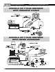
Both ignitions will install to most vehicles with a 12 volt electrical system and a distributor that
is triggered with points, electronic amplifiers or magnetic pickups.
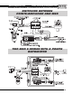
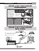
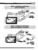
Wire Functions
The heavy Red connects to the battery positive (+) terminal. The heavy
Black connects the battery negative (-) terminal or other good engine
ground.
Connects to a switched 12 volts source.
Connects to the positive (+) coil terminal. This is the only wire that makes
electrical contact with the coil positive terminal.
Connects to the negative (-) coil terminal. This is the only wire that makes
electrical contact with the coil negative terminal.
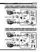
Connects to a points or amplifier trigger source. When this wire is used, the
Magnetic Pickup is not (Green and Violet).
These wires are routed into a 2-pin connector. It connects to the magnetic
pickup of an MSD Distributor or Crank Trigger. The Violet is mag positive
(+) and the Green is negative (-). If this connector is used, the White wire
will not be connected.
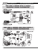
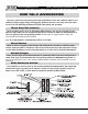
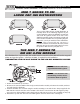
This wire is used to activate the Two Step Rev Limit. When 12 volts are
applied, the Launch rpm limit is activated.
This is the Retard activation wire. When 12 volts are applied, the Retard
stage is activated.
Magnetic Pickup Compensation circuit adjusts for different style pickups.
See page 45 for programming information.
PP
PP
P
oo
oo
o
wer Cables:wer Cables:
wer Cables:wer Cables:
wer Cables:
Red:Red:
Red:Red:
Red:
Orange:Orange:
Orange:Orange:
Orange:
Black:Black:
Black:Black:
Black:
WW
WW
W
hite:hite:
hite:hite:
hite:
Green/VGreen/V
Green/VGreen/V
Green/V
iolet:iolet:
iolet:iolet:
iolet:
Blue:Blue:
Blue:Blue:
Blue:
Pink:Pink:
Pink:Pink:
Pink:
Green Loop:Green Loop:
Green Loop:Green Loop:
Green Loop:
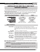
Operating Specifications Operating Specifications
Operating Specifications Operating Specifications
Operating Specifications
Digital-6 Plus Digital-6 Plus
Digital-6 Plus Digital-6 Plus
Digital-6 Plus
Digital-7 Plus Digital-7 Plus
Digital-7 Plus Digital-7 Plus
Digital-7 Plus
Operating VOperating V
Operating VOperating V
Operating V
oltage:oltage:
oltage:oltage:
oltage:
Current Requirements:Current Requirements:
Current Requirements:Current Requirements:
Current Requirements:
RR
RR
R
PP
PP
P
M Range:M Range:
M Range:M Range:
M Range:
Spark Series Duration:Spark Series Duration:
Spark Series Duration:Spark Series Duration:
Spark Series Duration:
PrimarPrimar
PrimarPrimar
Primar
y Vy V
y Vy V
y V
oltage:oltage:
oltage:oltage:
oltage:
Energy Output Max:Energy Output Max:
Energy Output Max:Energy Output Max:
Energy Output Max:
WW
WW
W
eight and Size:eight and Size:
eight and Size:eight and Size:
eight and Size:
12 - 18 Volts
.7 Amp per 1,000 rpm
12,500 w/ 14.4 Volts
20° Crankshaft
535 Volts
135 millijoules
3.7 lbs, 8.5”x4.5”x2.2
”
12 - 18 Volts
1.1 Amp per 1,000 rpm
12,500 w/ 14.4 Volts
20° Crankshaft
535 Volts
190 millijoules
3.7 lbs, 8.5”x4.5”x2.2”
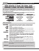
WARNING: When using a capacitive discharge ignition control, there is high voltage present
at the coil primary terminals. Never touch the coil or connect test equipment to
these terminals.
WARNING: During installation, disconnect the battery. When disconnecting the battery al-
ways remove the negative cable first and install it last.