
Technical information

AUTOTRONIC CONTROLS CORPORATION • 1490 HENRY BRENNAN, EL PASO, TEXAS 79936 • (915) 857-5200 • FAX (915) 857-3344
www.msdignition.com email: msdtech@msdignition.com
64
INSTALLING AN MSD 10 IGNITION CONTROL
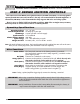
This section covers the MSD 10 Ignition Control. The MSD 10, PN 7500, is a race only ignition
system and is unique in that it incorporates two ignition coils. The MSD Pro Power Coil, PN 8201,
is the coil responsible for the Capacitive Discharge side of the ignition while the Pro Power Cou-
pler Coil, PN 8209R, is a high performance inductive coil. The coils run in parallel sending two
sparks that work as one. The CD is responsible for ionizing the spark plug gap, then the current
from both coils produce a high level of sustained spark for increased spark duration.
The MSD 10 also has a built-in Two Step Rev Control.
Operating Voltage: 12 - 18 volts
Current Requirements: 17 Amps @ 8,000 rpm
RPM Range: 13,000 rpm with 14.4 volt supply
Spark Duration: CD Coil; 20° Crankshaft
Inductive Coil; 20° - 30° Crankshaft
Primary Voltage Output: 520 Volts
Spark Energy: CD Coil; 130 milliJoules per spark
Inductive Coil; 500 milliJoules stored
Weight and Size: 4.8lbs., 9"L x 4"W x 5.75"H
Operating Specifications
Wire Functions
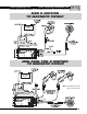
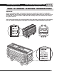
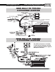
The MSD 10 features two terminal strips.
The heavy Red connects to the battery positive (+) terminal. The
heavy Black connects the battery negative (-) terminal or other
good engine ground.
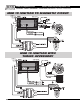
Connects to a switched 12 volts source.
Connects to the positive side of the Pro Power Coupler Coil.
Connects to the negative side of the Pro Power Coupler Coil.
Connects to the negative (-) coil terminal. This is the only wire
that makes electrical contact with the coil negative terminal.
Connects to the positive (+) coil terminal. This is the only wire that
makes electrical contact with the coil positive terminal.
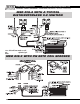
This is the trigger input terminal for points, amplifiers, a timing
control or from an ECU. If this is connected, the magnetic pickup
terminals will not be used.
These are the magnetic pickup terminals that connect to an MSD
Distributor or Crank Trigger. If these terminals are connected, the
Points terminal will not be used.
This is the tach output terminal. It provides a 12 volt square wave
signal that most tachometers will accept.
This is the Two Step activation terminal. When this wire is
grounded, Module 2 is activated. When not grounded, Module 1 is
active.
This can be used as an emergency kill switch. When grounded, the
ignition system is turned Off.
PP
PP
P
oo
oo
o
wer Cables:wer Cables:
wer Cables:wer Cables:
wer Cables:
Ignition (Red):Ignition (Red):
Ignition (Red):Ignition (Red):
Ignition (Red):
PP
PP
P
oo
oo
o
wer Coil + (Red):wer Coil + (Red):
wer Coil + (Red):wer Coil + (Red):
wer Coil + (Red):
PP
PP
P
oo
oo
o
wer Coil – (Blue):wer Coil – (Blue):
wer Coil – (Blue):wer Coil – (Blue):
wer Coil – (Blue):
CC
CC
C
D Coil - (Black):D Coil - (Black):
D Coil - (Black):D Coil - (Black):
D Coil - (Black):
CC
CC
C
D Coil + (Orange):D Coil + (Orange):
D Coil + (Orange):D Coil + (Orange):
D Coil + (Orange):
PP
PP
P
oints (Woints (W
oints (Woints (W
oints (W
hite):hite):
hite):hite):
hite):
Mag + (VMag + (V
Mag + (VMag + (V
Mag + (V
iolet):iolet):
iolet):iolet):
iolet):
TT
TT
T
ach (Graach (Gra
ach (Graach (Gra
ach (Gra
y):y):
y):y):
y):
TT
TT
T
wo Step (Ywo Step (Y
wo Step (Ywo Step (Y
wo Step (Y
elloello
elloello
ello
w):w):
w):w):
w):
Kill (BroKill (Bro
Kill (BroKill (Bro
Kill (Bro
wn):wn):
wn):wn):
wn):
Mag – (Green)Mag – (Green)
Mag – (Green)Mag – (Green)
Mag – (Green)