OPERATING MANUAL TRUNKED PORTABLE RADIO 7243 LTR-NET™ PORTABLE UHF
LAND MOBILE PRODUCT WARRANTY - The manufacturer’s warranty statement for this product is available from your product supplier or from E.F. Johnson Company, 299 Johnson Avenue, Box 1249, Waseca, MN 56093-0514. Phone (507) 835-6222. Copyright© 2001 by the E.F. Johnson Company The E.F. Johnson Company, which was founded in 1923, provides wireless communication systems solutions for public safety, government, and commercial customers.
SAFETY TRAINING INFORMATION SAFETY TRAINING INFORMATION WARNING This radio produces RF electromagnetic energy when transmitting and is designed and classified for “Occupational Use Only”. Radio equipment with this classification must be used only during the course of employment by individuals aware of the hazards and the ways to minimize such hazards. This radio is NOT intended for use by the General Population in an uncontrolled environment.
SAFETY TRAINING INFORMATION • DO NOT transmit more than 50% of total radio use time (50% duty cycle). Transmitting for more than 50% of the time can cause FCC RF exposure compliance requirements to be exceeded. This radio is transmitting whenever Tx is indicated in the lower right corner of the display. Pressing the PTT switch on the side usually causes the radio to transmit. • DO NOT use any accessories not specifically authorized by the E.F.
TABLE OF CONTENTS TABLE OF CONTENTS SAFETY TRAINING INFORMATION . . . . . . . . . . . . . . . . . . . . . . . . 4 QUICK REFERENCE GUIDE . . . . . . . . . . . . . . . . . . . . . . . . . . . . . . . 9 FEATURES . . . . . . . . . . . . . . . . . . . . . . . . . . . . . . . . . . . . . . . . . . . . . 10 General Features . . . . . . . . . . . . . . . . . . . . . . . . . . . . . . . . . . . . . . . . 10 LTR-Net Features . . . . . . . . . . . . . . . . . . . . . . . . . . . . . . . . . . . . . . .
TABLE OF CONTENTS TELEPHONE CALLS. . . . . . . . . . . . . . . . . . . . . . . . . . . . . . . . . . . . . 30 General . . . . . . . . . . . . . . . . . . . . . . . . . . . . . . . . . . . . . . . . . . . . . . . 30 Placing Telephone Calls . . . . . . . . . . . . . . . . . . . . . . . . . . . . . . . . . . 30 Receiving a Telephone Call . . . . . . . . . . . . . . . . . . . . . . . . . . . . . . . 31 Landside-Originate Telephone Calls . . . . . . . . . . . . . . . . . . . . . . . .
TABLE OF CONTENTS CONVENTIONAL FEATURES . . . . . . . . . . . . . . . . . . . . . . . . . . . . . 48 Squelch Adjust . . . . . . . . . . . . . . . . . . . . . . . . . . . . . . . . . . . . . . . . . 48 Monitoring Before Transmitting . . . . . . . . . . . . . . . . . . . . . . . . . . . 49 Transmit Disable On Busy . . . . . . . . . . . . . . . . . . . . . . . . . . . . . . . . 50 Talk-Around . . . . . . . . . . . . . . . . . . . . . . . . . . . . . . . . . . . . . . . . . . . 51 Call Guard Squelch. . . . . .
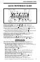
QUICK REFERENCE GUIDE QUICK REFERENCE GUIDE Phone Group System Scan List Dial Mode Low Power S L BUSY 8-Character Alphanumeric Display Group Scan List Monitor Scan Call Priority C P2 Tx UID Low UID/Aux Conv Ch Battery Group Busy G Keypad Transmitter Keyed Lock Change system number - Press SYS or or SYS (1-99) [pg 21] Change group number - Press GRP or or GRP (1-99) [pg 21] System scan on/off - FCN SCAN ( indicates scanning is enabled) [pg 40] Change scan list status of displayed system - FC
FEATURES FEATURES General Features • • • • • • • • • • LTR-Net™, LTR®, and conventional operating modes Unique 8-character system identification tags System and group scan User programmable system and group scan lists Menu mode to select various functions Three programmable option switches Call progress tones Call indicator Receive-only groups Companding LTR-Net Features • • • • • • Roaming (automatic locality search) Standard group (mobile-to-mobile) calls Special calls including telephone, unique ID
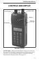
CONTROLS AND DISPLAY CONTROLS AND DISPLAY On-Off/Volume Option Switch Antenna Jack Speaker Accessory Connector Microphone Top Panel Controls On-Off Volume - Turning this knob clockwise turns power on and sets the volume level. Turning it counterclockwise to the detent turns power off. Power is on when information appears in the display. For more information on setting the volume, refer to page 20.
CONTROLS AND DISPLAY Option Switch 1 - This switch can be system operator programmed to control a specific function (see page 35). Antenna Jack - Connection point for the antenna. Accessory Connector - When the protective cover is removed, this connector can be used for connecting optional accessories. Battery Release Button (Not shown) - This button is located on the bottom end of the transceiver, and it is pressed to release the battery so that it can slide downward and be removed from the radio.
CONTROLS AND DISPLAY Phone Group System Scan List Dial Mode Low Power S L Scan Call C BUSY 8-Character Alphanumeric Display Group Scan List Monitor UID Low UID/Aux Conv Ch Battery Group Busy Priority P2 G Tx Keypad Transmitter Keyed Lock Display 8-Character Alphanumeric Display - This area of the display indicates the selected system/group (see “System/Group Display Mode” on page 20), the dialed number (see “Dial Mode” on page 37), error conditions, and other information.
CONTROLS AND DISPLAY - Indicates that the conventional monitor mode has been enabled by the Monitor option switch (see page 49). P2 - “P” indicates that the displayed group is an LTR-Net/LTR priority 1 group, and “P2” indicates that it is a priority 2 group (see page 45). G - Indicates that the displayed group is in the scan list and scanned normally (see page 42). BUSY - Indicates that the selected conventional channel is currently busy with voice or other traffic. - Indicates a low battery condition.
CONTROLS AND DISPLAY Front Panel Keys Most front panel keys have two or more functions. The function on the key is usually selected by simply pressing the key, and the function under the key is usually selected by first pressing another key such as the FCN key. In addition, some key functions may be available in the standard mode and others in the dial mode (see page 37). Also, all key functions except 0-9 can be assigned to an option switch and controlled by either (see page 35).
CONTROLS AND DISPLAY SYS (RCL) Standard Mode SYS - Selects the next higher system. SYS - Selects the next lower system. SYS (xx) - Directly selects specified system. FCN RCL - Momentarily displays the revert (selected) system if it is not already being displayed. Dial Mode RCL - Scrolls through the numbers programmed in memory. FCN RCL (0-9) - Recalls the number stored in the specified memory location. FCN RCL - Recalls the last number dialed from memory. FCN RCL - Recalls the last number dialed.
CONTROLS AND DISPLAY Dial Mode 2 - Dials the “2” digit. FCN PHONE - Exits the dial mode and sends the call termination code. 3 (DIAL) Standard Mode FCN DIAL - Selects the dial mode without changing the currently selected group. 3 - Pressing this key with the PTT switch pressed transmits the “3” digit. Dial Mode 3 - Dials the “3” digit. FCN DIAL - Exits the dial mode without sending the call termination code. 4 (PAGE) Standard Mode FCN PAGE - The page function is currently not available.
CONTROLS AND DISPLAY Dial Mode 6 - Dials the “6” digit. 7 (S.A/D) Standard Mode FCN S.A/D (System Add/Delete) - Changes the scan list status of the currently displayed system. The system is in the scan list and scanned normally if “ S ” is displayed when not scanning. 7 - Pressing this key with the PTT switch pressed transmits the “7” digit. Dial Mode 7 - Dials the “7” digit. 8 (SEND) Standard Mode 8 - Pressing this key with the PTT switch pressed transmits the “8” digit. Dial Mode 8 - Dials the “8” digit.
CONTROLS AND DISPLAY Dial Mode 0 - Dials the “0” digit. FCN STR (0-9) - Stores the displayed number in the specified memory location. ( ) Standard Mode - Pressing this key with the PTT switch pressed transmits the “ ” digit. SYS - Selects the next lower system (see preceding “SYS” key description). GRP - Selects the next lower group (see preceding “GRP” key description). Dial Mode - Dials the “ ” digit. FCN - Enters a pause when dialing a telephone number.
BASIC OPERATION BASIC OPERATION Power-Up Sequence When power is turned on using the top panel on-off/volume control, the backlight turns on, all segments and icons in the display are momentarily enabled, and the last seven digits of the transceiver part number are very briefly displayed. A beep then sounds (if tones are enabled) and the transceiver is operational. Backlight Operation The display and keypad backlight automatically turns on for 3 seconds whenever power is turned on or any key is pressed.
BASIC OPERATION modes, press FCN STR. Turning power off does not change the selected mode. These modes operate as follows: Numeric Mode - The system and group numbers are displayed as “Sxx Gxx” and the group alpha tag is not displayed. For example, System 1 and Group 2 are displayed as follows. When only group scanning is occurring, the group number is replaced by dashes and the system number continues to be displayed (see page 40).
BASIC OPERATION selected, a tone sounds and wrap-around to the highest system or group occurs. • To directly select a system or group number, press SYS or GRP and then the number of the desired system or group. For example, to select Group 9, press GRP, 0, 9. A leading “0” must be entered for digits 1-9 for the selected system or group to change.
BASIC OPERATION Low Battery Indication When the battery voltage drops to the point where recharging is required, the icon is indicated in the bottom part of the display. In addition, a beep sounds when this indication initially appears and when the push-to-talk switch is released (if the key press tone is enabled). The battery should be recharged as soon as possible after this indication appears (see page 57).
BASIC OPERATION LTR-Net and LTR Operation The LTR-Net and LTR modes provide automatic channel selection and monitoring before transmitting. Special tones and display messages indicate busy and out-of-range conditions, and telephone calls can be placed almost as conveniently as with your home telephone. Selecting a system selects a collection of up to 99 groups.
GENERAL FEATURES GENERAL FEATURES Bank Select A bank is a collection of selectable systems that have been set up for a specific application. For example, one bank could be programmed for operation in Minneapolis and another for operation in Milwaukee. Up to sixteen banks can be programmed, and each bank is identified by a unique alpha tag. Banks are selected by the BANK SEL menu parameter.
GENERAL FEATURES Home System/Group Select To select the preprogrammed Home system/group, simply press the FCN HOME. The Home system/group programmed for the current bank is then displayed and it becomes the selected system/group. If no home system/group has been programmed, this function is not available. Proceed (Clear-To-Talk) Tone This is a short tone that sounds shortly after the PTT switch is pressed to indicate that the radio system has been accessed and speaking can begin.
STANDARD GROUP CALLS Time-Out Timer The time-out timer disables the transmitter if it is keyed continuously for longer than the programmed time. It can be programmed for 0.5 - 5.0 minutes or disabled entirely. If the transmitter is keyed continuously for longer than the programmed time, the transmitter is disabled, “TIMEOUT” is indicated in the display and the intercept tone sounds. The timer and tone are reset by releasing the PTT switch.
STANDARD GROUP CALLS Placing a Standard Group Call 1. Turn transceiver power on and set the volume as described starting on page 20. With conventional operation, also make sure that the squelch is properly set as described on page 48. 2. Select the system and group of the mobile being called as described on page 21. 3. If a conventional call is being placed, monitor the channel manually or automatically as described on page 49. 4.
STANDARD GROUP CALLS • If the radio system could not be accessed because of an out-of-range condition or some other reason, the intercept tone sounds (see page 52) and “NO ACESS” is indicated in the display. The PTT switch must then be released and pressed again to make another access attempt. • When responding, busy or no access conditions may also occur, the same as when placing a call because the radio system is re-accessed for each transmission with these calls.
TELEPHONE CALLS TELEPHONE CALLS General NOTE: Telephone calls can be placed and received only if that service is available to you and your transceiver has been programmed appropriately. The telephone calling feature allows you to place and receive telephone calls using your transceiver. The following information describes how these calls are made with LTR-Net and LTR operation.
TELEPHONE CALLS • If the radio system is busy or could not be accessed, busy or no access conditions are indicated the same as described for standard group calls on page 28. • With LTR-Net operation, a short tone sounds to indicate that the number was accepted by the system. 5. When the other party answers, press the PTT switch and respond. The PTT switch must be pressed to talk and released to listen (the same as with standard group calls). 6.
LTR-NET AUXILIARY CALLS Landside-Originate Telephone Calls If telephone calls can be placed, it is usually possible to receive telephone calls from a landside telephone. With some radio systems, each mobile is assigned a unique telephone number so that it can be dialed directly. With others, the number of the radio system is dialed and then when a tone sounds, the number specifying the mobile being called is dialed. The mobile user hears “ringing” when a telephone call is received.
LTR-NET AUXILIARY CALLS 3. Select the dial mode by pressing FCN DIAL. This mode is indicated when the handset portion of the telephone icon is displayed. 4. Dial the desired number which specifies the mobile or group of mobiles being called. If it has been previously stored, this number can be recalled from memory by pressing FCN RCL and the location number (0-9). Refer to the dial mode description starting on page 37 for more information. 5.
OPTION SWITCHES AND MENU MODE The transceiver may be programmed so responses always occur on the last selected group. In this case, the group may need to be manually changed to respond to these calls (see “Transmitting In The Scan Mode” on page 43). Unique ID and Directed Group calls can also be placed from a landside telephone. The same numbers are dialed as when the call is mobile originated. Contact your system operator for more information on how to place these calls.
OPTION SWITCHES AND MENU MODE Option Switches The push-button switch on the top panel (see page 11) and the switch immediately above and the switch immediately below the PTT switch on the side panel (see page 12) are programmable by your system operator. The functions which can be controlled by these switches are basically the functions that are selectable by the front panel keys plus monitor mode select (see “Option Switch” column of the preceding table).
OPTION SWITCHES AND MENU MODE • To display the selected option for a parameter, press the STR key. • To change the selected option, press the • To exit back to the parameter and save the selected option, press FCN STR. • To exit back to the parameter without changing the selected option, press STR. and keys. 3. When the desired condition of each menu parameter is selected, exit the menu mode by pressing FCN MENU again.
DIAL MODE DIAL MODE Introduction When placing calls that require a number be dialed (telephone and auxiliary), using the dial mode allows the number to be dialed at any convenient rate, dialing errors to be corrected, and then the radio system to be automatically accessed and number transmitted when desired. The dial mode also allows up to ten 16-digit numbers to be stored in memory and later recalled. When in the dial mode, the SYS and GRP keys become RCL (Recall) and CLR (Clear) keys.
DIAL MODE Dialing a Number Enter the desired number by pressing the 0-9, # , and dialing functions are as follows: keys. Other • Only the last 8 digits dialed are displayed. To momentarily display the upper 8 digits, press FCN . • To erase the last digit, press the CLR key (hold it down to repeat). To erase the entire number, press FCN CLR. • To enter a pause, press FCN (each pause equals one character). Sending the Number Briefly press the PTT switch to access the radio system.
DIAL MODE NOTE: The character is stored and sent normally (no pause occurs), and the # character should not be stored because it may terminate the call when it is sent. Recalling Numbers From Memory From Specific Location - FCN RCL 0-9 (location number) Stored in Next Location - RCL (hold down to repeat). If a number is already displayed, the number in the next higher location is indicated; if display is blank, the number in location 1 is indicated first.
SYSTEM AND GROUP SCANNING SYSTEM AND GROUP SCANNING General Introduction The scan feature monitors, in sequence, the systems and/or groups in the scan list. When a message is detected that the transceiver is programmed to receive, scanning stops and the message is received. Shortly after the message is complete, scanning resumes (unless it has been disabled). System and group scanning or group scanning only may be used (see next page), and the operation of each type is as follows.
SYSTEM AND GROUP SCANNING System Scan List S System or Group Scanning Selected Group Scan List G Group Scanning Occurring Scan Types The type of scanning selected is determined by the menu mode SCN TYPE parameter (see page 35). If it is not selectable, the scan type is fixed by system operator programming. The available scan types are as follows.
SYSTEM AND GROUP SCANNING systems are not scanned). If roaming is enabled, registration on other sites occurs normally and scanning of LTR-Net systems occurs as just described. However, if the current LTR-Net site is lost and no other LTR-Net site can be located, the LTR and conventional systems in the scan list are also scanned. Searching for an LTR-Net site continues and if one is again detected, registration on that site occurs and the LTR and conventional systems are no longer scanned.
SYSTEM AND GROUP SCANNING Systems and groups can be deleted from the scan list in the normal manner while listening to a message on the system or group by simply pressing the S.A/D or G.A/D key. Scanning resumes shortly after the system or group is deleted. Saving Scan List If the menu mode SCN SAVE parameter is available (see page 35), you can select if scan list changes are saved. If “On” is selected, changes are saved as they are made and the scan list does not change when power is turned off.
SYSTEM AND GROUP SCANNING to the new system/group, or changes temporarily. This in turn affects the system/group on which responses occur. The display always indicates the system/group on which a call is received, but this may not be the system/ group on which a response occurs. The three programmable configurations operate as follows: Last Selected - Transmissions always occur on the system/group that was selected manually by the SYS and GRP keys or automatically by roaming.
LTR-NET AND LTR FEATURES LTR-NET AND LTR FEATURES Transmit Inhibit The Transmit Inhibit feature prevents the transmitter from keying if the mobile you are calling is busy with another call. When the transmitter is disabled by this feature, the intercept tone sounds and “TX INHIB” is displayed (see following illustration). To make another call attempt, the PTT switch must be released and pressed again.
LTR-NET FEATURES LTR-NET FEATURES NOTE: Other LTR-Net features are described starting on page 45. LTR-Net Standard Calls Standard group calls are between two mobiles or between a mobile and a control station. To place these calls in the LTR-Net or LTR mode, simply select the desired group and press the PTT switch (no number is dialed) as described starting on page 27.
LTR-NET FEATURES Roaming LTR-Net radio localities (sites) can be linked together to provide wide area coverage. Calls can then be automatically routed to your current location as you travel from locality to locality. Both standard group and special calls may be routed in this manner. If your transceiver is programmed for roaming, this feature is utilized as follows: 1. Enable roaming using the ROAMING menu parameter (see page 34) if available.
LTR FEATURES LTR FEATURES NOTE: Other LTR features are described starting on page 45. Standard Group Calls Standard group calls are between two mobiles or between a mobile and a control station. To place these calls in the LTR or LTR-Net mode, simply select the desired group and press the PTT switch (no number is dialed). The procedure for placing and receiving these calls is described starting on page 27.
CONVENTIONAL FEATURES 3. Press the key until receiver noise is heard and then press until the noise just mutes. To decrease or increase the selected level in steps of 10 (or select the minimum or maximum level if this is not possible), press FCN or FCN , respectively. NOTE: Slight readjustment may be required if weak messages are not heard or unsquelching occurs when no messages are present. 4. To exit this mode, press the FCN SQL again. Exiting also occurs automatically after 2 seconds of no activity. 5.
CONVENTIONAL FEATURES Busy Indicator BUSY Monitor Mode There may be times when the Busy indication is displayed even though no one is using the channel. Monitoring should then be performed using the monitor mode. This mode is enabled and disabled by pressing the Monitor option switch (see page 35), and is indicated by in the display as shown in the following illustration.
CONVENTIONAL FEATURES While the PTT switch is pressed, the receiver is enabled so that activity on the channel can be monitored. The PTT switch must be released and then pressed again to make another call attempt. Occasionally, a busy condition may be detected even though no one is talking. To key the transmitter in this case, release the PTT switch and then immediately press it again.
MISCELLANEOUS MISCELLANEOUS Supervisory Tones The following tones are heard at various times when operating this transceiver. Some or all of these tones may be disabled by the TONES menu parameter or programming (see “Tone Select” on page 27). Busy Tone This tone is similar to the standard telephone busy tone, and it indicates that the radio system is currently busy. The display also indicates “BUSY” while this tone is sounding.
MISCELLANEOUS is displayed, the transmitter has been disabled by the Transmit Inhibit feature (see page 45). • Receive-Only Group - If this tone sounds when the push-to-talk switch is pressed and “TX DISBL” is displayed, the group is receiveonly (see page 26). Proceed (Clear-To-Talk) Tone - This is a short single or double tone which sounds after the push-to-talk switch is pressed to indicate when talking can begin (see page 26).
MISCELLANEOUS Proceed Dialing Tone - When placing a landside-to-mobile telephone call (see page 32), the landside caller may enter a special number which specifies the mobile being called. This tone indicates when that number should be dialed. LTR Telephone Call Tones The following tones are generated by LTR interconnect equipment and are heard when making LTR telephone calls. Reorder Tone - Three beeps which indicate that the call has been terminated by the system.
MISCELLANEOUS BUSY - Indicates that the LTR-Net or LTR radio system is currently busy (see “Busy Tone” on page 52). CALL SVC - Indicates that the transceiver is inoperative. Contact your system operator for service. DSBL BSY - Indicates that the transmitter is disabled by the conventional Transmit Disable On Busy feature (see page 50). It also indicates that the transmitter was keyed while receiving an LTR-Net or LTR call.
MISCELLANEOUS OUT-LOCK - Indicates that the synthesizer is unlocked. Refer to “Transceiver Service” on page 61 for more information. PROG ERR - Indicates an EEPROM read error. Refer to “Transceiver Service” on page 61 for more information. SLEEPING - Indicates that the transceiver has been temporarily disabled by the system operator. It will be automatically enabled again when operation can be resumed. SQUELCH - Indicates that the conventional squelch adjust mode is selected (see page 48).
MISCELLANEOUS SCN CONT - Scan continue on-off • ON or OFF SCN SAVE - Scan list save • ON = save, OFF = not saved SCN TYPE - Selects type of scanning • SYSTEM - Both system and group • GROUPS - Group scanning only • OFF - All scanning disabled S/G DISPL - System/group display mode • ALPHA • NUMERIC TONES - Beep tones select • SILENT - All tones disabled • KEYS - Only Select switch and key press tones sound • ALERTS - All tones sound except preceding Key Beeps sound • ALL - All the preceding tones sound Rec
MISCELLANEOUS Typical operating time before recharging is required is 7.3 hours. This assumes that the transceiver is transmitting at high power 5% of the time, receiving and producing audio 5% of the time, and in the standby mode (receive with audio muted) 90% of the time. If the low-power mode is selected or different times are spent in these modes, operating time varies accordingly. The charge of the battery and ambient temperature also affect operating time.
MISCELLANEOUS Battery Charger Operation Fast Charge Slot Fast Charge Slot Indicator Slow Charge Slot Slow Charge Slot Indicator The charger shown above has two slots in which to place a battery. The back slot is for fast charging and the front slot is for slow charging. Only the battery can be inserted in the fast charge slot and the entire transceiver can be inserted in the slow charge slot if desired. Batteries can be charged in both slots at the same time.
MISCELLANEOUS charging is occurring, and charging continues at the slow rate until the battery is removed from the charger. Approximate charge time in this slot for a fully discharged battery is 20 hours (with transceiver power off if applicable). If transceiver power is on, this slot basically maintains the charge of the battery.
INDEX Licensing A government license is usually required to operate this transceiver on the air. Your system operator will normally handle the licensing requirements. Transceiver Service If your transceiver is not operating properly, “OUT-LOCK”, “PROG ERR”, “SLEEPING”, or “CALL SVC” may be displayed. It may be possible to clear the first two conditions by turning power off and then on again to reset the control logic. Also, make sure that the controls are properly set and the battery is fully charged.
INDEX Controls On-Off/Volume 11 Option Switch 12 PTT Switch 12 Top Panel 11 Conventional Mode 24 Conventional Mode Scanning 42 D DIAL Key 17 Dial Mode 37 Exiting 39 Selecting 37 Dialing a Number 38 Directed Group Call 32, 46 Disabling Keypad 22 Display 13 Display Messages 54 Display Mode Alpha Tag 21 Numeric 21 F Fast Charge 59 FCN Key 15 Features Conventional 10 General 10 LTR 10 LTR-Net 10 Front Panel Keys 15 G G.
INDEX N Numeric Display Mode 21 O On-Off/Volume Control 11 Operating Modes 23 Operation at Extended Range 60 Option Switch 12, 23, 35 Monitor Mode Select 50 P PAGE Key 17 PHONE Key 16 Power-Up Sequence 20 Priority Calls 45 Proceed Tone 26 Push-to-Talk Switch 12 Q Quick Reference Guide 9 R RCL Key 16 Recalling a Number 39 Receive-Only Groups 26 Rechargeable Battery Pack 57 Roaming 47 S S.
002-7200-600 Part Number 002-7200-600 9-01 hph Printed in U.S.A.