LTR® 98xx SERIES HIGH TIER OPERATING MANUAL Part No.
LAND MOBILE PRODUCT WARRANTY - The manufacturer’s warranty statement for this product is available from your product supplier or from the E.F. Johnson Company, 299 Johnson Avenue, Box 1249, Waseca, MN 56093-0514. Phone (507) 835-6222. Copyright© 1999 by the E.F. Johnson Company The E.F. Johnson Company, which was founded in 1923, designs, manufactures, and markets radio communication products, systems, and services worldwide. E.F.
SAFETY INFORMATION SAFETY INFORMATION The FCC has adopted a safety standard for human exposure to RF energy. Proper operation of this radio under normal conditions results in user exposure to RF energy below the Occupational Safety and Health Act and Federal Communication Commission limits. WARNING DO NOT allow the antenna to touch or come in very close proximity with the eyes, face, or any exposed body parts while the radio is transmitting.
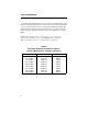
SAFETY INFORMATION FCC EXPOSURE LIMITS This mobile radio transceiver was tested by the manufacturer with an appropriate antenna in order to verify compliance with Maximum Permissible Exposure (MPE) limits set under Section 2.1091 of the FCC Rules and Regulations. The guidelines used in the evaluation are derived from Table 1 (B) titled “Limits For General Population/Uncontrolled Exposure” which is from FCC report OET bulletin #65.
SAFETY INFORMATION of a domestically manufactured 4-door passenger sedan. The radio manufacturer has determined that the user and service personnel should remain one (1) meter in distance away from the antenna when transmitting. By maintaining this distance, these individuals are not exposed to radio frequency energy or magnetic fields in excess of the guidelines set forth in Table 1.
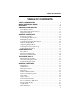
TABLE OF CONTENTS TABLE OF CONTENTS SAFETY INFORMATION . . . . . . . . . . . . . . . . . . . . . . . . . . . . . . . . . . 4 QUICK REFERENCE GUIDE . . . . . . . . . . . . . . . . . . . . . . . . . . . . . . . 9 FEATURES . . . . . . . . . . . . . . . . . . . . . . . . . . . . . . . . . . . . . . . . . . . . . 10 CONTROLS AND DISPLAY. . . . . . . . . . . . . . . . . . . . . . . . . . . . . . . 11 Front Panel Controls. . . . . . . . . . . . . . . . . . . . . . . . . . . . . . . . . . . . .
TABLE OF CONTENTS Tone Select . . . . . . . . . . . . . . . . . . . . . . . . . . . . . . . . . . . . . . . . . . . . 30 Transmitter Thermal Foldback . . . . . . . . . . . . . . . . . . . . . . . . . . . . . 30 OPTION SWITCHES AND MENU MODE . . . . . . . . . . . . . . . . . . . 30 Option Switches . . . . . . . . . . . . . . . . . . . . . . . . . . . . . . . . . . . . . . . . 30 Menu Mode Introduction . . . . . . . . . . . . . . . . . . . . . . . . . . . . . . . . . 32 Using Menu Mode . . . . . . . . . . .
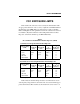
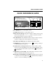
QUICK REFERENCE GUIDE QUICK REFERENCE GUIDE Red - Transmit Amber - Transmit (Reduced Pwr) Green - Busy Conv. Group (Channel) On-Off/Volume (Press/Rotate) Select Switch (Press/Rotate) Group Scan System Scan Encryption Monitor List List Phone Horn Scan Option Call Priority Group Alert Selected ID Power On/Off - Press on-off/volume control. Set Volume Level - Rotate on-off/volume control. Change System or Group - Press Select switch to enable system or group select mode (indicated by ←/→ or __).
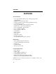
FEATURES FEATURES General Features • • • • • • • • • • • • • • • Up to approximately 100 1-group or 40 16-group systems programmable LTR® and conventional operation Unique 8-character system and group identification tags System and group scan User programmable system and group scan lists Menu mode to control various functions Five programmable option switches Up to 16 banks selectable Proceed (clear-to-talk) tone Call indicator Time-out timer Horn alert Emergency switch Receive-only groups Companding and
CONTROLS AND DISPLAY CONTROLS AND DISPLAY Transmit/Busy Indicator Microphone Jack Option Switches On-Off/Volume Speaker Select Switch Front Panel Controls On-Off Volume - Pressing this knob turns power on and off. The vehicle ignition switch may also control power as described in “Power Turn-Off Delay” on page 27. Rotating this knob sets the speaker volume (see page 15).
CONTROLS AND DISPLAY Option Switches - The five front panel option switches can be programmed by your system operator for the functions which follow. Refer to the section indicated for more information on a function. The key cap usually indicates the function controlled by the switch.
CONTROLS AND DISPLAY Speaker - The internal speaker is located behind the grille. An optional speaker can be connected to the external speaker jack located on the back. See “Speaker Jack” description which follows. Antenna Jack Power Jack Speaker Jack Rear Panel Jacks and Connectors Antenna Jack - Miniature UHF jack for connecting the 50-ohm antenna. Power Jack - Connection point for the power cable which attaches to the vehicle battery. A nominal 12-volt DC, negative ground power source is required.
CONTROLS AND DISPLAY System Scan List Encryption Phone Scan ID Selected Horn Alert Call 16-Character Message Area Priority Group Scan Groups List Option Monitor Display Description 16-Character Message Area - Indicates the selected system and group (see page 16) and also error conditions and status information. - Indicates that the displayed system is in the scan list and scanned normally (see page 35). - Indicates that the displayed group is in the scan list and scanned normally (see page 35).
GENERAL OPERATION - Indicates that a call has been received on a group programmed for a call indicator (see page 24). To turn this indication off, press any key. - Indicates that the monitor mode is enabled. This mode disables Call Guard squelch and other squelch control features so that all messages are heard on conventional systems (see page 44). - When only is displayed, the selected or displayed group is scanned as a first priority group.
GENERAL OPERATION Backlight Operation The display and keypad backlight can be controlled by the BACKLIGHT menu parameter (see page 38). The three states that can be selected are Bright, Dim, and Off. If this menu parameter is not selectable, the backlight is fixed in one of these states by programming. System/Group Display Information The currently selected system and group are displayed using either a Numeric or Alpha Tag display mode.
GENERAL OPERATION Selecting the System and Group The front panel Select switch is used to change the system and group. Pressing this switch toggles between the system and group select modes, and then rotating it increases or decreases the system or group. In the Numeric display mode (see preceding description), the system select mode is indicated when the arrow points to “Sxx”, and the group select mode is indicated when it points to “Gxx” (see following diagram).
GENERAL OPERATION Setting Squelch Control NOTE: This procedure sets the squelch level used for conventional calls only. The squelch level for LTR calls is preset and not affected by this adjustment. For more information on the various operating modes, refer to page 38. If conventional systems are programmed, the squelch level can be set if the FCN option switch is enabled. Proceed as follows: 1. Select a conventional system and then a group that is not busy.
STANDARD CALLS STANDARD CALLS Introduction Most calls you make are probably the standard type described in this section. These calls are between you and another mobile or control station. The main difference between these calls and the other type that can be placed (telephone calls) is that no number is dialed using a keypad. The following procedure applies to both LTR and conventional operation. Placing a Standard Call 1. Turn transceiver power on and set the volume as described starting on page 15.
STANDARD CALLS • If an out-of-range condition exists, the intercept tone sounds (see page 47) and “OUT-RNGE” is indicated on the lower line of the display. No more access attempts are made once this indication appears. Release the PTT switch and drive closer to the radio system or away from shielding structures and try again.
TELEPHONE CALLS TELEPHONE CALLS Placing Telephone Calls NOTE: Telephone calls can be placed and received only if that service is available to you and your transceiver has been programmed appropriately. A microphone equipped with a telephone keypad is required to dial the telephone number. The telephone calling feature allows you to place and receive telephone calls using your transceiver. The following information describes how these calls are made with LTR operation.
TELEPHONE CALLS Out-of-Range - If the System Search feature is selected (see page 42), that feature is automatically selected when the PTT switch is released. The System Search mode is indicated by “SYS SRCH” in the display. 4. With the dial tone sounding, dial the number using the 0-9 keys on the microphone keypad. If the microphone has a memory, you may also be able to recall the number from memory. The PTT switch does not need to be pressed while you are dialing if the transmitter automatically keys.
GENERAL FEATURES Landside-Originate Calls Calls can be placed from a landside telephone to your transceiver if the radio system and transceiver have that capability. With most systems, a mobile can be called directly (each has a unique telephone number). With others, a mobile may be called as follows: 1. Dial the number of the radio system in which the mobile is operating. 2. When the system answers, a short tone sounds to indicate that the number of the mobile should be dialed.
GENERAL FEATURES Call Indicator The call indicator is “C” in the upper part of the display as shown in the following illustration. The purpose of this indication is to show that a call was received while you were away from the vehicle. Individual groups can be programmed for this feature and it then turns on when a call is received on one of those groups. Call Indicator This indicator is turned off by pressing any button or turning transceiver power off and then on.
GENERAL FEATURES Each group can be programmed so that when it is selected, encryption is automatically enabled. When encryption is enabled, is indicated in the display as shown below. Encryption Indicator If you have the ENCRYPT menu parameter or ENCPT option switch, the encryption group programming can be temporarily overridden. Selecting another system or group causes encryption to revert to the status programmed for that group. Encrypted calls are received even if encryption is not enabled.
GENERAL FEATURES Squelch Adjust - Pressing FCN and then rotating the Select switch with a conventional system selected sets the squelch level as described on page 18. Home System/Group Select To select the preprogrammed Home system/group, simply press the FCN switch and then the Select switch. The Home system/group is then displayed and it becomes the selected system/group. If no home group has been programmed, the last selected group of the home system is selected.
GENERAL FEATURES Manual Off/On Mode The horn alert mode does not change when power is turned on and off by either the ignition switch or power switch. Therefore, the horn alert is entirely controlled by either the HORN option switch or menu parameter. Auto Off/On Mode Ignition Switch - The horn alert always turns off when the ignition switch is turned on, and always turns on when the ignition switch is turned off (if there is a turn-off delay).
GENERAL FEATURES A power turn-off delay allows features such as the horn alert and call indicator to remain active for a time after the ignition switch is turned off. At the same time, advantages of ignition switch control are utilized such as preventing battery discharge that may occur if the transceiver is accidentally left on for an extended period (see page 54).
GENERAL FEATURES Receive-Only Groups Any group can be programmed for monitoring only (transmitting is disabled). If the PTT switch is pressed with one of these groups selected, the intercept tone sounds and “TX DSBL” is displayed. Stealth Mode The stealth mode disables the following tones and indicators so that they do not reveal that you are transmitting or otherwise indicate your presence. The speaker audio and display remain enabled in this mode.
OPTION SWITCHES AND MENU MODE Tone Select If the TONES menu parameter is selectable, the tones that sound can be selected. Otherwise, the tones that sound are fixed by programming. The following choices are available. Refer to page 32 for more information on using the menu mode. Silent - All tones are disabled. Key Beep - Only the Select switch and key press tones are enabled. Alert - All tones except the preceding Key Beep tones are enabled. All Tones - Both the Key Beep and Alert tones are enabled.
OPTION SWITCHES AND MENU MODE Menu Mode and Option Switch Functions Function Menu Items Option Switch Add/delete (scan list prg) --A/D Backlight adjust BACKLGHT --Bank select BANK SEL --Call Guard Sq.
OPTION SWITCHES AND MENU MODE Menu Mode Introduction The menu mode is selected by pressing the FCN switch twice. If this switch is not programmed, the menu mode is not available. Functions which can be controlled by the menu mode are indicated by an entry in the “Menu Items” column of the table on page 31. Refer to the page listed in the table for a description of the function. Some functions may not be used, may be in a fixed state, or may be controlled by an option switch.
SYSTEM AND GROUP SCAN • • • Pressing the FCN switch again Pressing the PTT switch Automatically when time-out occurs 2 seconds after a change is made or 8 seconds after no changes are made. NOTE: Calls cannot be received or transmitted while the menu mode is selected. SYSTEM AND GROUP SCAN Introduction The scan feature monitors, in sequence, the programmed systems and/or groups in the scan list.
SYSTEM AND GROUP SCAN System Scan List System or Group Scanning Selected Group Scan List System or Group Scanning Occurring The type of scanning selected is determined by the menu mode SCN TYPE parameter (see page 32). If that parameter is not selectable, the type of scanning is fixed by programming. The available scan types are as follows.
SYSTEM AND GROUP SCAN Scan List Programming General NOTE: The selected (displayed) system and group are always scanned, even if they are deleted from the scan list. The system and group scan lists are programmed using the A/D (add/delete) option switch. Pressing this switch changes the status of the displayed system or group. The displayed system is in the scan list and scanned normally when is displayed.
SYSTEM AND GROUP SCAN “Off” is selected, they are no longer saved. Therefore, to store a list, select “On”, program the list, then select “Off”. Then when power is turned on, the scan list returns to the state that existed when “Off” was selected. If the menu SCN SAVE parameter is not selectable, the scan list save mode is fixed by programming. If “On” is programmed, all changes are saved and no change occurs in the scan lists when power is cycled.
SYSTEM AND GROUP SCAN Last Selected - The selected system/group does not change when calls are received on other system/groups. Therefore, to respond to a message not on the selected system/group, one of the following methods must be used. With this configuration, the display may not indicate the system/ group on which the response occurs. • Select the system/group of the call manually using the Select switch. • Before scanning resumes, exit the scan mode by pressing the SCAN switch.
LTR AND CONVENTIONAL MODES LTR AND CONVENTIONAL MODES General Each selectable system can be programmed for LTR or conventional operation by your system operator. The type or types of operation that are programmed in your transceiver are determined by the type of radio equipment being used in your radio system. The differences in operation are described in the following information and elsewhere in this manual as required.
LTR AND CONVENTIONAL MODES To properly receive calls in the conventional mode, the squelch control must be set as described in page 18. If this control is not set properly, weak messages could be missed or noise could be heard when no message is present. In the LTR mode, the squelch level is fixed and setting this control has no affect.
LTR FEATURES following illustration. The monitor mode can also be enabled by the MON or CG option switch if it is programmed. Refer to the monitor mode description on page 44 for more information. Monitor Mode Selected LTR FEATURES Standard and Telephone Calls Standard calls are between two mobiles or between a mobile and a control station. Telephone calls allow you to place and receive calls over the public telephone system using your transceiver.
LTR FEATURES If a call is received on one of the fixed priority ID codes, either “PRIORTY1” or “PRIORTY2” is displayed on the bottom line. The selectable groups are then checked to see if any have the same ID code. If a match is found, the transceiver changes to that group. If no match is found, the group does not change and a response cannot be made on that ID code. The “Transmitting in the Scan Mode” programming described on page 36 determines if a change is temporary or permanent.
LTR FEATURES Busy Queuing The LTR busy queuing feature places a telephone call in a queue if the radio system is busy when it is placed. Then when the system becomes available, the call is automatically placed. Standard (mobile-tomobile) calls are not queued by this feature. If queuing is programmed and a busy condition is encountered, the queue mode is entered automatically when the PTT switch is released.
LTR FEATURES for a system within range. If enabled, the system search mode is automatically entered when the PTT switch is released. This mode is indicated by a short tone and “SYS SRCH” on the bottom line of the display as shown in the following illustration. The transceiver then attempts to access, in succession, other systems that have a group programmed for telephone calls. As each system is accessed, a beep sounds.
CONVENTIONAL FEATURES CONVENTIONAL FEATURES Monitor Mode The monitor mode is used to monitor a channel before transmitting. When this mode is selected, it temporarily disables Call Guard squelch or other squelch control techniques and also scanning so that all messages occurring on the selected group (channel) are heard. The monitor mode is enabled by taking the microphone off-hook (unless off-hook detection is disabled by programming) or pressing the MON option switch.
CONVENTIONAL FEATURES pressed. When the transmitter is disabled by this feature, the busy tone sounds briefly and “DSBL BSY” is indicated on the lower line of the display. The monitor mode (see preceding section) is enabled while the PTT switch is pressed so that activity on the channel can be monitored. However, it is not possible to access a channel by holding down the PTT switch (it must be released to make another attempt). Occasionally, a busy condition may be detected even though no one is talking.
CONVENTIONAL FEATURES Groups may also be programmed so that talk-around cannot be turned off. If the option switch is then pressed, neither “TA OFF” nor “TA ON” is displayed. If the menu mode is used in these cases, the current mode cannot be changed. Call Guard Squelch The Call Guard squelch feature eliminates distracting messages intended for others using the channel. This is done by using a subaudible tone or digital code to control the squelch.
MISCELLANEOUS complete, the transceiver returns to the previous system/group. If a message is still present, it is received. When a priority system/group is sampled while listening to a message on some other system/group, a series of “ticks” may be heard. These ticks are brief interruptions of the audio signal that occur when sampling takes place. If the menu mode PRIORITY parameter (see page 32) or the PRI option switch is available, priority sampling can be turned on and off.
MISCELLANEOUS • Out-Of-Range - If this tone sounds shortly after pressing the PTT switch and “OUT RNGE” is displayed, the transceiver was unable to contact a repeater. The usual cause for this is an out-of-range condition (see “Operation At Extended Range” on page 54). Once this tone sounds, no more access attempts are made until the PTT switch is released and then pressed again. This condition is not indicated with conventional operation.
MISCELLANEOUS Priority Call Tone - This is a short tone that sounds when a call is received on a conventional first or second priority channel (see page 46). Wrap-Around Tone - This is a two-pitch tone that indicates that the highest or lowest channel was displayed and that wrap-around has occurred. Error Tone - This is a two-pitch tone that indicates that an error condition has occurred.
MISCELLANEOUS Display Messages The following messages appear on the upper or lower line of the display to indicate various operating modes and error conditions. The group alpha tag appears in this area during normal operation. BLK CALL - Indicates that the call is being received on an LTR block ID code (see “Calls on Priority and Block ID Codes” on page 40). BUSY - Indicates that the LTR radio system is currently busy (see “Busy Tone” on page 47).
MISCELLANEOUS NO DT GP - Indicates that no valid data group could be found for a data transmission. NO POWER - Indicates that the transmitter temperature or supply voltage is excessive and that the transmitter has been automatically shut down. Release the PTT switch and allow the transmitter to cool. If the problem persists, contact your system operator for service. NO PHONE - Indicates that the LTR system search mode could not locate any systems programmed for telephone calls (see page 42).
MISCELLANEOUS TA ON or OFF - Indicates that talk-around was just enabled or disabled by the TA option switch (see “Talk-Around” on page 45). TIMEOUT - Indicates that the transmitter has been disabled by the Time-Out Timer (see page 29). TX DSBL - Indicates that the selected conventional system is programmed for monitoring only (see “Receive-Only Groups” on page 29). TX INHIB - Indicates that the transmitter has been disabled by the Transmit Inhibit feature (see page 41).
MISCELLANEOUS SCN TYPE - Selects type of scanning • SYS-GRP - Both system and group • GRP ONLY - Group scanning only • OFF - All scanning disabled S/G DISPL - System/group display mode • ALPHATAG • NUMERIC STEALTH - Stealth mode select • ON or OFF SYS SRCH - LTR system search • ON or OFF TALKARND - Conventional talk-around on-off • ON or OFF TONES - Beep tones select • SILENT - All tones disabled • KEY BEEP - Only Select switch and key press tones sound • ALERT - All tones sound except preceding Key Beeps
MISCELLANEOUS Operation At Extended Range When approaching the limits of radio range, the other party may not be able to hear your transmissions and there may be an increase in background noise when messages are received. You may still be out of range even though you can hear a message. The reason for this is that the signal you are receiving is usually transmitted at a higher power level than the one transmitted by your transceiver.
MISCELLANEOUS Transceiver Service If your transceiver is not operating properly, “OUT-LOCK” or “PROG ERR” may be displayed. To attempt to clear this condition, turn power off and then on again to reset the control logic. Another indication that could be displayed is “NO POWER”. This indicates that transmitter temperature or supply voltage may be excessive. Release the PTT switch and allow the transceiver to cool, and make sure that the vehicle battery voltage is within the normal range.
Part Number 002-9803-201 11-99hph Printed in U.S.