8500 Series OPERATING MANUAL FM Portable Radio Multi-Net® Intrinsically-Safe Viking CK FM Approved
SAFETY INFORMATION SAFETY INFORMATION The FCC has adopted a safety standard for human exposure to RF energy. Proper operation of this radio under normal conditions results in user exposure to RF energy below the Occupational Safety and Health Act and Federal Communication Commission limits. WARNING • DO NOT allow the antenna to touch or come in very close proximity with the eyes, face, or any exposed body parts while the radio is transmitting.
LAND MOBILE PRODUCT WARRANTY - The manufacturer’s warranty statement for this product is available from your product supplier or from the E.F. Johnson Company, 299 Johnson Avenue, Box 1249, Waseca, MN 56093-0514. Phone (507) 835-6222. Copyright© 1999 by the E.F. Johnson Company The E.F. Johnson Company, which was founded in 1923, designs, manufactures, and markets radio communication products, systems, and services worldwide. E.F.
NOTES NOTES 4
QUICK REFERENCE GUIDE QUICK REFERENCE GUIDE Change system number: S (System) Change group number: G (Group) Turn system scanning on or off: SCN Temporarily suspend system and group scanning in Multi-Net or LTR mode: Press Auxiliary switch on side. Lock out of scanning last-selected system or group: LCK Unlock all systems: LCK for 2 seconds Turn on backlight: Press upper switch on side. Return to home or last active system/group: RTN Disable or enable keypad: Turn power on with LCK pressed.
FEATURES FEATURES • Up to 14 systems selectable • Up to 11 groups selectable per system (Multi-Net) • Up to 10 channels selectable per system (conventional) • System scan • Group scan (Multi-Net Only) • System and group lockout when scanning • LCD display with backlight to indicate system and group numbers, 7character system or 5-character group identifier, and other information • Both Multi-Net (trunked) and conventional (non-trunked) operation • Repeater talk-around in conventional mode
TABLE OF CONTENTS TABLE OF CONTENTS SAFETY INFORMATION . . . . . . . . . . . . . . . . . . . . . . . . . . . . . . . . . . 2 QUICK REFERENCE GUIDE . . . . . . . . . . . . . . . . . . . . . . . . . . . . . . . 5 FEATURES . . . . . . . . . . . . . . . . . . . . . . . . . . . . . . . . . . . . . . . . . . . . . . 6 CONTROLS . . . . . . . . . . . . . . . . . . . . . . . . . . . . . . . . . . . . . . . . . . . . . . 9 DISPLAY INFORMATION. . . . . . . . . . . . . . . . . . . . . . . . . . . . . . . . .
TABLE OF CONTENTS Emergency Button . . . . . . . . . . . . . . . . . . . . . . . . . . . . . . . . . . . . . . 26 Transmit Inhibit . . . . . . . . . . . . . . . . . . . . . . . . . . . . . . . . . . . . . . . . 27 Priority Calls. . . . . . . . . . . . . . . . . . . . . . . . . . . . . . . . . . . . . . . . . . . 27 Keypad Disable . . . . . . . . . . . . . . . . . . . . . . . . . . . . . . . . . . . . . . . . 27 Key Press Tone Disable . . . . . . . . . . . . . . . . . . . . . . . . . . . . . . . . . .
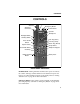
CONTROLS CONTROLS Antenna Accessory Connector Transmit Indicator Emergency Button On-Off/Volume Speaker Microphone Backlight Switch Auxiliary Switch Push-To-Talk Switch System Select Scan Key (Store) Lock Key (Clear) Return Key (Recall) Group Select Phone Mode Select Telephone Keypad Send Key Battery Release Button Battery Pack FRONT PANEL CONTROLS On-Off/Volume -Turning this knob clockwise turns power on and sets the volume. Turning it counterclockwise to the detent turns power off.
CONTROLS S (System) - Pressing this key increases the selected system. Holding it down causes the function to repeat. Only programmed systems can be selected. Turning power on with this switch pressed changes the loudness of the clear-to-talk tone. G (Group) - Pressing this key increases the selected group. Holding it down causes the function to repeat. Only programmed groups can be selected. SCN (Scan) - Turns the scan feature on and off.
CONTROLS Backlight Switch - Pressing this switch illuminates the display so that it can be viewed in low-light conditions. This switch is the upper part of the upper half of the rubber switchpad on the side. Speaker and Microphone - The internal speaker and microphone are located behind the grille in the locations shown. Battery Pack - Rechargeable nickel-cadmium (Ni-Cd) battery pack. OPTIONAL KEYS FOR TELEPHONE CALLS NOTE: Refer to “SPECIAL CALLS” on page 15 for more information on the following keys.
DISPLAY INFORMATION DISPLAY INFORMATION Alphanumeric Display System Display SYS MUTE GRP SCN PHON Group Display MON CALL BUSY S S C N L C K R T N STO CLR RCL G FRONT PANEL DISPLAY System Display - Indicates the selected system number. Group Display - Indicates the selected group number. SYS (System) - Always displayed above the system number. GRP (Group) - Always displayed above the group number. SCN (Scan) - Indicates that the scan mode has been selected by the SCN key.
DISPLAY INFORMATION tion appears when system or group scanning if any group has been locked out of the scan list. MUTE - Indicates that the key press tone has been muted by turning power on with the SCN key pressed. To re-enable this tone, turn power on again with the SCN key pressed. TX - Indicates that the transmitter is on. This indication appears in conjunction with the red transmit indicator next to the antenna. BUSY - Indicates that the channel is busy when a conventional system is selected.
STANDARD CALLS STANDARD CALLS Introduction Most calls that you make to others in your radio system are standard calls. When these calls are placed, all that is required is to select the desired system and group. No number needs to be entered on the telephone keypad as with special calls. Calls in the conventional mode are always standard calls. Placing a Standard Call 1. Turn power on and set the volume as required. 2. Select the desired system and group if applicable. 3.
SPECIAL CALLS resumes which is programmable for 1-7 seconds after the message ends. If you do not, another call may be received and you may have to change the system and group. Refer to “Transmitting In Scan” on page 22 for more information. SPECIAL CALLS Introduction Special calls include telephone calls, calls to specific mobiles or a dispatcher, calls to other Multi-Net sites, and others. These calls differ from standard calls in that a special number must be dialed after the system is accessed.
SPECIAL CALLS push-to-talk switch (if it is pressed) and a short tone should sound to indicate that the call was accepted by the system. After this tone sounds, a ringing or second short tone sounds as follows: A ringing tone indicates that the other party is being rung. If it is a telephone call and the line is busy, a busy tone may also sound. In this case, terminate the call by pressing the # key. When the party answers, continue the call as described in step 6.
SPECIAL CALLS Landside-Originated Calls Mobiles can also be called from a landside telephone. If the system is designed so that mobiles can be called directly, simply dial the telephone number of the mobile being called. If mobiles cannot be called directly, dial the number of the system. Then when the system answers, dial the special number which specifies the mobile being called. This number is supplied by your system operator, and it must be dialed using a tone-type telephone.
SPECIAL CALLS mode is entered. Then when the phone mode is exited by pressing the PHON key, the system and group that were displayed when the phone mode was entered are again displayed. The system and group may be changed in either mode by pressing the SYS or GRP keys. Dialing The Number The phone mode allows you to enter the telephone or mobile number at any convenient rate, correct any dialing errors, and then transmit the number when desired by pressing the SND (Send) key.
SUPERVISORY TONES 1-8. The number can then be changed if necessary and then transmitted by pressing SND. Telephone numbers can also be programmed by your system operator. A unique identification can then be stored in the unused positions of each 14-character location. For example, if the number has seven digits, the seven-character identification “RICHARD” can be stored with the number. Then when the number is recalled, “RICHARD” is flashed in the display followed by his telephone number.
SUPERVISORY TONES • If this tone sounds after the transmit indicator flashes several times and “NO SITE” appears in the display, an out-of-radio-range condition is indicated. To complete a call, you may need to get closer to your radio system. Once this tone sounds, no more access attempts are made until the push-to-talk switch is released and then pressed again.
SYSTEM SCAN Call Proceed Tone With certain non-telephone calls, ringing does not occur after the number is dialed. Instead, another short tone sounds after the confirmation tone to indicate that the audio path is complete and speaking can begin. End Call Tone This tone consists of three beeps, and it indicates that the end of the call has been detected by the system.
SYSTEM SCAN display always changes to the system of the call and usually changes to the group of the call. The selected system or group can be changed while scanning by simply pressing the system or group select switch. Scanning then halts and the selected system or group changes. Scanning resumes 1 second after a switch is released. Some transceivers may be programmed so that the conventional and some Multi-Net systems may not be scanned.
SYSTEM SCAN preceding section). For example, if System 1/Group 2 were displayed when scanning was turned on and a call is received on System 3/ Group 4, System 3/Group 4 are displayed and the call is received. If a response is then made to that call, the transmission occurs on System 3/Group 4. However, if the response is not made until after scanning resumes, the transmission occurs on the revert system/group (System 1/Group 2 in this case).
OTHER FEATURES System lockout is not available if you have only one selectable system, and group lockout is available only if the selected system is programmed for group scan (see page 25). The lockout status of all systems and groups is maintained when power is turned off. Scanning Multi-Net Systems NOTE: For information on Multi-Net and conventional systems, refer to page 29.
OTHER FEATURES cates that the radio system has been successfully accessed and speaking can begin. If no tone sounds and “BUSY” is indicated in the display, the system is busy. If you continue to hold down the push-to-talk switch, the system will be accessed and the clear-to-talk tone will sound when the system is available. If the selected system is programmed for conventional operation, the clear-to-talk tone does not sound.
OTHER FEATURES Call Indicator The call indicator is the word “CALL” in the lower part of the display. This feature indicates that a call was received while you were away from the transceiver. It is programmed by your system operator to turn on when calls are received on certain groups (Multi-Net systems) or channels (conventional systems). It may also be disabled entirely. This indication is turned off by pressing any key except backlight. Transceiver power must be on for this indicator to operate.
OTHER FEATURES from the dispatcher. A short tone sounds when this key is pressed. Contact your system operator for more information on the operation of this switch. Transmit Inhibit The Transmit Inhibit feature prevents the transmitter from turning on if the party you are calling is busy with another call. When the transmitter is disabled by this feature, the intercept tone also sounds and “TX INHIB” appears in the display. This feature is programmed by your system operator on Multi-Net systems only.
OTHER FEATURES be disabled. To disable all keys except push-to-talk and backlight, turn power on with the LCK key pressed. If a key is then pressed, all that happens is that “KEYLOCK” is displayed. To re-enable the keypad, simply turn power on again with the LCK key pressed. Key Press Tone Disable If the tone that sounds when a key is pressed is distracting or annoying, it can be disabled. To enable or disable this tone, turn power on with the SCN key pressed.
MULTI-NET AND CONVENTIONAL MODES MULTI-NET AND CONVENTIONAL MODES General This transceiver can operate in both the Multi-Net and conventional modes. Each selectable system can be programmed for either type of operation. The type of operation that is programmed is determined by the type of radio equipment in use in the radio system you are accessing. You can probably assume that Multi-Net operation has been programmed unless you are told otherwise.
CONVENTIONAL MODE OPERATION CONVENTIONAL MODE OPERATION Monitoring Before Transmitting Before transmitting in the conventional mode, regulations require that you monitor the channel to make sure that it is not being used by someone else. If you were to transmit while someone else was talking on the channel, you would probably disrupt their conversation. The simplest way to monitor the channel is to note if “BUSY” is indicated in the lower part of the display.
CONVENTIONAL MODE OPERATION turned on by quickly releasing and then pressing the push-to-talk switch. If “MON” is indicated in the display as described in the preceding section, the transmitter will turn on even if the channel is busy. When this feature is disabled, the transmitter always keys, even if the channel is busy.
OPERATION WITH OPTIONAL REMOTE CONTROL UNIT OPERATION WITH OPTIONAL REMOTE CONTROL UNIT Power Switch Volume Up/Down Switches System/Group Identification System Up/Down Switches System Number Group Number Volume Level Group Up/Down Switches Introduction This transceiver can be converted to a mobile transceiver by plugging it into the optional vehicle adapter if it has been installed in the vehicle. This adapter also provides rapid recharging of the transceiver battery.
OPERATION WITH OPTIONAL REMOTE CONTROL UNIT additional features available with a control unit are a power turn-off delay and horn alert. The operation of the Remote Control Unit with this transceiver is described in the following information. Control Unit Controls PWR - Turns both control unit and transceiver power on and off. Power is also controlled by the vehicle's ignition switch. Therefore, that switch must also be on to turn power on.
OPERATION WITH OPTIONAL REMOTE CONTROL UNIT P2 (RTN) - Selects either a home system/group or the last active system/ group, depending on programming by your system operator. In the phone mode, this key is used to sequentially recall telephone numbers from memory. MON (Auxiliary) - Turns the monitor mode on and off when a conventional system is selected. This key and the AUX key perform the same function HORN - Turns the horn alert on and off if it has been installed.
OPERATION WITH OPTIONAL REMOTE CONTROL UNIT keypad cannot be used). If the number is dialed using the microphone keypad, the phone mode probably does not need to be selected. Turning Power On and Off - Power to both the transceiver and control unit is controlled by the control unit PWR switch. However, the vehicle’s ignition switch also normally controls power. Therefore, it must be in the ON or ACCESSORY position for power to turn on.
MISCELLANEOUS INFORMATION are continuously lighted (when power is on) for use in low-light conditions. Sending Status Information When the remote control unit is used, status information can be transmitted to your dispatcher when a Multi-Net system is selected. If this feature has been programmed by your system operator, one of up to eight status conditions can be selected using the STATUS key. The currently selected status condition is transmitted whenever the transmitter is keyed.
MISCELLANEOUS INFORMATION Busy Queuing The busy queuing feature places the call in a queue if the repeater system is busy when the call is placed. Then when the system becomes available, a tone sounds and the call can be placed if desired. Busy queuing is either enabled or disabled on all Multi-Net systems by system operator programming. It functions with both standard and special calls. It is not available on LTR or conventional systems.
MISCELLANEOUS INFORMATION ular feature operates, contact your system operator. The only userprogrammable feature of this transceiver is the seven telephone numbers (if your transceiver is equipped with the optional telephone keypad). However, even that may not be user programmable if the location has been locked by your system operator (see “Storing and Recalling Numbers From Memory” on page 18).
MISCELLANEOUS INFORMATION TX INHIB - Indicates that the selected group is temporarily busy. This message is not displayed in the conventional mode. SYN ERR - Indicates a frequency synthesizer error. Refer to “Transceiver Service” on page 42. PRG ERR - Indicates that no transmit frequency has been programmed for the selected system. Refer to “Transceiver Service” on page 42. RX PRI1 - Indicates that a call has been received on the first priority group (see “Priority Calls” on page 27).
MISCELLANEOUS INFORMATION the side upward and rotate the pack counterclockwise (when viewed from the bottom). To install a pack, insert it in the socket and rotate it clockwise until it locks in place. A new pack must be charged before use. Battery Operating Time Typical operating time before recharging is required depends on what model of transceiver you have and also how you use it. The 8560/70 models have fixed power output and the 8565 model has user-selectable high and low power outputs.
MISCELLANEOUS INFORMATION Charger Part Number Approximate Charge Time Trickle 563-0001-003 Rapid 239-5800-400/-476 Vehicular Adapter Rapid 239-5810-500 16 hours 2 hours 2 hours It is good practice to remove the battery from the charger after it is fully charged. Regularly leaving a fully charged battery in the charger for an extended period (such as longer than overnight or over a weekend), may shorten battery life.
INTRINSICALLY SAFE CLASSIFICATION Transceiver Service If the transceiver is not operating properly, “SYN ERR” or “PROG ERR” may be displayed. It is also possible that all segments of the display are indicated when power is turned on. To attempt to clear this condition, turn the power off and then on again to reset the control logic. Also make sure that the battery is charged, the controls are properly set, and the antenna is tight.
INTRINSICALLY SAFE CLASSIFICATION Classification of Areas (Division) Areas are classified as Division 1or 2 as shown below. Since a Division 1 area is considered most hazardous, a transceiver approved for a specific Division 1 atmosphere can also be used in the same Division 2 atmosphere. The intrinsically safe rating applies to Division 1 areas and the nonincendive rating applies to Division 2 areas.
FM Approved Part Number 002-8571-378 12-99hph Printed in U.S.