7780 PRELIMINARY SERVICE MANUAL Series SMARTNET™/SMARTZONE® PORTABLE 778x (800 MHz) SMARTNET™/SmartZone®/Conventional 7.5 VDC, 1 and 3 Watts 806-824 MHz Transmit 851-870 MHz Receive Part No.
7780-SERIES SMARTNET ™/SMARTZONE ®/CONVENTIONAL FM TWO-WAY PORTABLE RADIO 7.5 VDC 806-824 MHz Transmit, 851-870 MHz Receive 1-Watt (Low Power), 3-Watts (High Power) Part No. 242-778x-50x Copyright ©1999 by the E.F. Johnson Company E.F. Johnson Company, which was founded in 1923, designs, manufactures, and markets radio communication products, systems, and services worldwide. E.F.
TABLE OF CONTENTS TABLE OF CONTENTS 1 GENERAL INFORMATION 1.1 1.2 SCOPE OF MANUAL . . . . . . . . . . . . . . . . . . . .1-1 EQUIPMENT DESCRIPTION . . . . . . . . . . . . .1-1 Introduction. . . . . . . . . . . . . . . . . . . . . . . . . . . . . 1-1 Operating Protocols . . . . . . . . . . . . . . . . . . . . . . 1-1 Intrinsically Safe Models . . . . . . . . . . . . . . . . . . 1-1 Systems, Channels, and Zones . . . . . . . . . . . . . . 1-1 NPSPAC Models . . . . . . . . . . . . . . . . . . . . . . . .
TABLE OF CONTENTS TABLE OF CONTENTS (CONT’D) 3.2 3.3 3.4 3.5 3.6 4.2 PCTrunk Software Installation . . . . . . . . . . . . . . 3-1 Connecting RPI To Computer and Transceiver . 3-2 Starting and Exiting . . . . . . . . . . . . . . . . . . . . . . 3-2 Programming File Types . . . . . . . . . . . . . . . . . . 3-2 Help Files . . . . . . . . . . . . . . . . . . . . . . . . . . . . . . 3-2 Screen Types . . . . . . . . . . . . . . . . . . . . . . . . . . . 3-2 File Size Indication. . . . . . . . . . . . .
TABLE OF CONTENTS TABLE OF CONTENTS (CONT’D) 6.3 6.4 6.5 6.6 6.7 6.8 6.9 7 LIST OF TABLES MODULATION BALANCE. . . . . . . . . . . . . . . .6-4 AUDIO DEVIATION. . . . . . . . . . . . . . . . . . . . . .6-5 DATA DEVIATION. . . . . . . . . . . . . . . . . . . . . . .6-5 SQUELCH ADJUST . . . . . . . . . . . . . . . . . . . . .6-5 RSSI ADJUST . . . . . . . . . . . . . . . . . . . . . . . . . .6-5 RECEIVER PERFORMANCE TESTS . . . . . .6-6 Preliminary Setup . . . . . . . . . . . . . . . . . . . . . . . .
GENERAL INFORMATION SECTION 1 GENERAL INFORMATION 1.1 SCOPE OF MANUAL models is also used to service these models. Refer to Section 1.10 for more information on the intrinsically safe rating and additional requirements for servicing intrinsically safe models. This service manual contains operating, programming, alignment, and service information for the E.F. Johnson 7780 800 MHz portable transceiver. 1.2.4 SYSTEMS, CHANNELS, AND ZONES 1.
GENERAL INFORMATION RI FKDQQHOV GHFUHDVHV DV WKH QXPEHU RI 6PDUW1HW V\VWHPV LQFUHDVHV 7KH SURJUDPPLQJ VRIWZDUH GLVSOD\V D EDU JUDSK ZKLFK VKRZV WKH DPRXQW RI DYDLO DEOH PHPRU\ VSDFH WKDW LV XVHG E\ WKH FXUUHQW GDWD 5HIHU WR 6HFWLRQ IRU PRUH LQIRUPDWLRQ 1.
GENERAL INFORMATION Table 1-1 Accessories Customer Service Department can be reached using one of the following telephone numbers: Accessory Toll-Free: (800) 328-3911 (From within continental United States only) Part No.
GENERAL INFORMATION 1.10 INTRINSICALLY SAFE INFORMATION are times when the technicians have specific questions that need to be answered in order to completely identify and repair a problem. NOTE: Contact your sales representative to determine the availability of intrinsically safe models. When returning equipment for repair, it is also a good idea to use a PO number or some other reference number on your paperwork in case you need to call the repair lab about your unit.
GENERAL INFORMATION ignition of a particular atmosphere if two of the faults specified in the testing procedure occur. In other words, it must be able to withstand two simultaneous unrelated breakdowns without causing ignition. To receive a nonincendive rating, the transceiver needs to withstand only a single fault without causing ignition of a particular atmosphere. tion.
GENERAL INFORMATION Table 1-2 Material Classification Typical Hazard Group Class Acetylene Hydrogen Ethylene, ethyl ether, cyclopropane Gasoline, naphtha, butane, propane, alcohol, acetone, benzol, natural gas Metal dust including aluminum, magnesium, and their alloys Carbon black, coal, or coke dust Flour, starch, or grain dusts Ignitable fibers/flyings such as rayon or cotton A B C D I I I I E II F G - II II III 1.
GENERAL INFORMATION 4. Remove the PC board by lifting it upward. The RFto-logic board connector under the IF board must unplug, so some resistance may be encountered. Do not pull on the IF or PLL board assemblies because they can be easily damaged. LOCK UNLOCK 1.11.5 REMOVING LOGIC UNIT 1.11.4 REMOVING RF UNIT 1. Remove the top panel knobs. Then remove the spanner nuts on the quick select and on-off/volume switches. Remove the plastic top panel. 1.
GENERAL INFORMATION 7780 SPECIFICATIONS The following are general specifications intended for use in testing and servicing the transceiver. For current advertised specifications, refer to the 7780 product information sheet available from your E.F. Johnson sales representative. Specifications are subject to change without notice.
TRANSCEIVER OPERATION SECTION 2 TRANSCEIVER OPERATION 2.1 FEATURES able with the enhanced keypad model are also available with the limited keypad model. The features not available with the limited (3-key) model are as follows: 2.1.
TRANSCEIVER OPERATION F1 F2 F3 ENT 1 2 3 4 5 6 7 8 9 CLR * 0 # F3 F1 F2 Figure 2-1 Limited Keypad Model ENT Figure 2-2 Full Keypad Model 2.2.2 TOP PANEL INDICATORS FCN (Function) - This is a dealer programmable switch that can control various functions (see Section 2.3.4). TX Indicator (Red) - Indicates when the transmitter is keyed. RX Indicator (Green) - Indicates that the channel may be busy because a carrier is being detected.
TRANSCEIVER OPERATION Scan Enabled Telephone Call In Scan List RadioWide Scan Talk-Around Monitor Mode Mode Private Call Priority Channel Keypad Prog. Mode Alphanumeric Display Low Tx Power Busy Channel Low Battery Keypad Locked Figure 2-3 Display 2.2.5 FRONT PANEL KEYS (FULL KEYPAD MODEL) Alphanumeric Display - This eight-character area of the display indicates alphanumeric messages and feature selection information.
TRANSCEIVER OPERATION • BUSY - A busy system or transmit channel is being detected by the Busy Channel Lockout feature (see Section 2.4.5). - The battery needs recharging (see Section 2.3.6). - The keypad has been locked by pressing the Keypad Lock option switch (see Section 2.3.5). 2.3.3 BACKLIGHT The backlight for the display and keypad can be manually turned on by pressing the Backlight option switch if it is available. It can also be dealer programmed to automatically turn on when any key is pressed.
TRANSCEIVER OPERATION Table 2-1 Option Switch Functions 2.3.6 LOW BATTERY INDICATION When the battery voltage falls below a preset level, the icon appears in the display. This icon stays on until power is turned off.
TRANSCEIVER OPERATION disabled and vice versa. More information on these modes follows. channel it can be programmed for times from 15 seconds up to 3 minutes, 45 seconds or disabled (not used). If the transmitter is keyed continuously for longer than the programmed time, the transmitter is disabled and an invalid condition tone sounds. Five seconds before time-out occurs, an alert tone sounds to indicate that time-out is approaching. The timer and tone are reset by releasing the PTT switch.
TRANSCEIVER OPERATION • • Determining Which Channels are in Scan List To turn radio wide scanning off, press the Radio Wide Scan option switch again. The icon is then no longer indicated and “RWS OFF” is displayed briefly. Channels in the radio wide and standard SMARTNET/SmartZone scan lists are not indicated. With standard conventional scanning, the selected channel is in the current scan list if the box icon (around “S”) is indicated in the upper left corner of the display.
TRANSCEIVER OPERATION 2.4.2 DISPLAY MODE SELECTION ation). Monitoring before transmitting may not occur automatically in this mode, so the channel may have to be manually monitored before transmitting (see Section 2.4.3). Selecting a conventional channel selects a transmit and receive frequency and other parameters such as Call Guard squelch coding. If the Displayed Information option switch is programmed, the display mode used to indicate conventional channels can be user selected.
TRANSCEIVER OPERATION 2.4.4 MONITOR MODE 2.4.6 CALL GUARD SQUELCH The monitor mode temporarily disables squelch control features (such as Call Guard squelch) so that all messages are heard on the selected channel. It also overrides the Busy Channel Lockout feature (see next section) and temporarily halts scanning. General Call Guard® squelch (also called CTCSS/DCS signaling) can be programmed on conventional channels.
TRANSCEIVER OPERATION switch again, that icon is no longer displayed and “RTA OFF” is flashed. Changing channels or turning power off does not change the selected talk-around mode. to that channel are then reassigned to all the other channels in the current zone. The reassignments remain in effect even after power is cycled. 3. To restore all Call Guard codes in the current zone to the original settings, press the “0” key. 2.4.10 POWER OUTPUT SELECT 2.4.
TRANSCEIVER OPERATION Transmitting in Scan Mode 1. Press the Scan option switch to enable scanning. The currently selected scan list is momentarily indicated as “Scan x”, where “x” is the list number (1-3). Each conventional scan list can be programmed for one of the following modes. These modes determine if priority sampling occurs and also the channel on which transmissions occur while scanning. Refer to the next section for more information. 2.
TRANSCEIVER OPERATION Placing a Standard Conventional Call channel is sampled while listening to a message on some other channel. 1. Turn power on and set the volume as described in Section 2.3.2. Select the channel programmed for the mobile you want to call (see Section 2.3.7). The priority sampling times are programmed by the following parameters: Lookback Time A - This time determines how often the priority channel is checked for activity. Times of 0.25-4.00 seconds in 0.
TRANSCEIVER OPERATION Post-TX ANI - A preprogrammed ANI sequence is automatically sent each time you release the PTT switch. • If the radio system cannot be accessed within 500 ms of pressing the PTT switch, a continuous tone sounds until the system is accessed or the PTT switch is released. • If your unit ID is invalid, the call is being made to an invalid group ID, or group calls are not allowed, “INVALID ID” is displayed and an alert tone sounds. Disabled - All DTMF signaling is disabled. 2.
TRANSCEIVER OPERATION 2. Enter the index of the desired ID if you know it or scroll through the list using the and keys until you find the desired ID. Press the CLR key to cancel the call. • If neither your radio nor the radio being called is authorized to make unit-to-unit calls, “REJECT” is displayed and a continuous tone sounds. End the call by pressing the CLR key. 3. Press the PTT switch or the ENT key to initiate the call. The display then indicates the alias of the destination radio.
TRANSCEIVER OPERATION 3. Press the PTT switch to initiate the call. The display then indicates the alias of the destination radio. Wait approximately 1 second and then begin talking. Proceed to the bulleted list which follows the next method for conditions that may then occur. displayed. When the system is no longer busy, the call back tone (four beeps) is heard and your radio automatically starts transmitting. Press the PTT switch to continue the call.
TRANSCEIVER OPERATION 3. Press the PTT switch or the ENT key to initiate the call. The display indicates “WAIT” while the connection to the phone system is occurring. Once connected, the normal dial tone is heard and the alias of the number being called is displayed. The radio then automatically dials the telephone number and the normal ringing or busy tone is heard. Proceed to the bulleted list which follows the next method for conditions that may then occur. 2.
TRANSCEIVER OPERATION • If an out-of-range condition exists or the radio system is not in service, “LOST CALL” is displayed and a continuous tone sounds. End the call by pressing the CLR key. • If you are not authorized to make telephone calls, “REJECT” is displayed and a continuous tone sounds. End the call by pressing the CLR key. • If the radio system is busy, “BUSY” is displayed and a busy tone sounds. The call automatically proceeds when the radio system becomes available.
TRANSCEIVER OPERATION 2. To change the displayed status, enter the index of the desired status if you know it or scroll through the list using the and keys until you find the desired status. Press the CLR key to cancel this function. Answering a Page 1. When a page is received, the display alternately indicates “PAGE RCV” and the alias of the current channel and a recurring received page tone sounds (six beeps) sounds. 3. Press the PTT switch or the ENT key to send the status.
TRANSCEIVER OPERATION ning disabled. Then when a channel is selected again that permits scanning, it is automatically re-enabled. Emergency Calls An emergency call urgently requests access to a voice channel. To place this call, proceed as follows: In addition to calls on channels in the scan list, pages, private calls, and telephone calls are received while scanning. Messages on the priority channel are received while listening to lower priority messages.
TRANSCEIVER OPERATION • currently registered on a site, “SITE x” is displayed, where “x” is the site number. If the site is locked (see following), “LOCK x” is displayed instead. The display then indicates the RSSI (Receive Signal Strength Indicator) value of the current site as “RSSI x” and then returns to displaying the channel alias. • • • Searching For a New Site The time-out timer is about to expire or the penalty timer has expired (Sections 2.3.9 and 2.4.7).
TRANSCEIVER OPERATION Six Beeps 2.7.2 MENU DESCRIPTION • A menu is used to select parameters to be changed in the keypad programming mode. When the Keypad Programming mode is selected by pressing the option switch, the “P” and “G” icons are displayed (see Figure 2-3) along with the first menu parameter “ZONE CHG”. • • The paged radio received the page and acknowledged it (Section 2.5.7). The message that was sent has been received and acknowledged (Section 2.5.8).
TRANSCEIVER OPERATION 2.7.4 CHANNEL CHANGE PARAMETER 2.7.6 CHANNEL PARAMETERS The “CHAN CHG” menu parameter selects the conventional channel to be reprogrammed. Disabled or SMARTNET/SmartZone channels cannot be selected. This does not change the channel selected for normal operation. The “CHAN PRM” menu parameter selects the conventional channel parameter to be reprogrammed (see following). Press the and keys to display the desired parameter and then press the ENT key to select it.
TRANSCEIVER PROGRAMMING SECTION 3 TRANSCEIVER PROGRAMMING Remote Programming Interface (RPI) Part No. 023-9800-000 RPI-Transceiver Programming Cable Part No. 597-2002-123 Figure 3-1 Programming Setup 3.1 GENERAL NOTE: With the descriptions which follow, it is assumed that you have a basic understanding of how to use your Windows-based operating system. If you are not familiar with some of the Windows functions described, refer to your Help Screens and manuals included with your Windows software. 3.1.
TRANSCEIVER PROGRAMMING Windows 95/98 - Select Start > Settings > Control Panel and double click “Add/Remove Programs”. Then click Install and Next. When SETUP.EXE is automatically located on the floppy drive, click Next, select the location for the start-up icon, and enter the name you want to call the program. Modular Connector PROGRAMMING CABLE Part No. 597-2002-122/-123 4 To Radio Accessory Connector 6 2 8 9 7 5 3 8 6 4 2 1 5 9 1 4. Follow the instructions displayed by the setup program.
TRANSCEIVER PROGRAMMING System - These screens program the parameters that are unique to the displayed Conventional, SMARTNET, or SmartZone system. The system to be edited is selected as described in Section 3.1.10. one conventional system can be set up, and it is automatically created when a programming file is opened as described in Section 3.1.6. Therefore, there is no option to add a conventional system. Channel - This screen programs unique channel parameters and assigns channels to each zone.
TRANSCEIVER PROGRAMMING 3.2.2 PROGRAMMING RADIO WIDE PARAMETERS 3.2.5 PROGRAMMING RADIO (DOWNLOADING FILE) 1. To display the Radio Wide screens, click the Radio Wide button or select Window > Radio Wide Parameters in the menu bar (see Section 3.1.8). When all the required programming information has been entered in the various programming screens, the information can be programmed (downloaded) into the radio.
TRANSCEIVER PROGRAMMING 3.3.4 UPLOAD MENU Open - Opens a programming file that was previously saved to disk. If a modified file is currently open, you are asked if that file should be saved before the new file is opened. Close - Closes the current file. If the file has been modified and the changes have not been saved, you are asked if the changes should be saved before closing. The Upload Menu is displayed only in the opening screen before a programming file is created.
TRANSCEIVER PROGRAMMING 3.3.7 HELP MENU programmed. Currently, only 800 MHz 77xx models are available. Zones Contents - Displays the help system table of contents. Total Zones - The total number of zones currently set up. The maximum number allowed is 16. Zones are added by clicking the Add button (see following). Search For Help On - Displays the search dialog box that allows searching for a help topic by keyword. Current Zone - Indicates the currently selected zone.
TRANSCEIVER PROGRAMMING Radio Wide Scan List NOTE: The radio-wide scan list cannot be programmed until all channels to be included have been set up as described in the Conventional and SMARTNET/SmartZone sections (3.5 and 3.6, respectively). Clicking the Radio Wide Scan List button in the General screen displays the following screen which programs the radio-wide scan list described in Section 2.3.11.
TRANSCEIVER PROGRAMMING Full Spectrum CC Scan 2. To program a switch, click the arrow to display the pull-down menu and then select the desired function from that menu. NOTE: Side Button 1 is the top (AUX) button and Side Button 2 is the bottom (FCN) button. Also, the * and # keys are not available with limited keypad (3-key) models. 3. Repeat for all switches and modes to be programmed and then exit this screen by clicking the Close button.
TRANSCEIVER PROGRAMMING LED Indicator - Selects if the top panel BAT LED indicates a low battery condition. after the control channel returns from the Voice On Control mode. 3.5 PROGRAMMING CONVENTIONAL SYSTEMS AND CHANNELS Adjustable Parameters Busy Override Delay - With SmartZone operation, this is the amount of time a user must press the PTT switch to override a SmartZone busy that occurs because some member of the talk group is present at a site where there are no traffic channels available. 3.5.
TRANSCEIVER PROGRAMMING NOTE: The conventional scan lists cannot be programmed until all the conventional channels are programmed. Therefore, first program the channels as described in Sections 3.5.3 and 3.5.4. Timers Tx Time-Out Timer - This timer limits the length of transmissions (Section 2.3.9). Times up to 3 minutes, 45 seconds in 15-second steps can be programmed. To modify a list, click and the screen which follows is displayed.
TRANSCEIVER PROGRAMMING Priority Channel Selection also the type of priority channel (see the “Priority Channel” description which follows). The following modes are available: The Scan Mode parameter in the preceding Conventional System Scan List screen selects if priority channel sampling is enabled on the selected scan list. It also selects the type of priority channel (either fixed or the selected) if applicable. No Priority - Priority sampling does not occur (all channels are scanned in sequence).
TRANSCEIVER PROGRAMMING Figure 3-3 Conventional Channel Screen 3.5.4 CONVENTIONAL CHANNEL SCREEN PARAMETERS The following parameters are programmed in the conventional channel screen shown in Figure 3-3. The parameters in this screen are as follows: Selected Channel Zone Box - Clicking the arrow to the right of this box displays the available zones. Click on a zone to select it. Zones and zone aliases are set up on the RadioWide General screen described in Section 3.4.2.
TRANSCEIVER PROGRAMMING Signaling NOTE: Channel numbers not assigned must be programmed for conventional operation and then not enabled in the above screen because SMARTNET/ SmartZone channels cannot be disabled. Off - No ANI signaling is used. Leading ANI - A DTMF-coded ID is sent at the beginning of each transmission. This ID is set in the radio-wide conventional screen (Section 3.4.3). Channel Type Channel Type Box - Selects the specific system from which the channel is selected.
TRANSCEIVER PROGRAMMING 3.6.2 SMARTNET/SMARTZONE SYSTEM GENERAL SCREEN all other frequencies. When it is disabled, deviation is 5 kHz with all frequencies. PTT ID Enables or disables the PTT ID. System Lists Button This button displays the screens used to program the various lists that are unique for each SMARTNET/ SmartZone system. Refer to Section 3.6.7 for more information on these lists. Dynamic Regrouping Enable For This System - When this box is checked, a dynamic regrouping channel is enabled.
TRANSCEIVER PROGRAMMING 3.6.3 SMARTNET/SMARTZONE SYSTEM OTHER ID’S SCREEN Disabled - Telephone calls cannot be placed or received. Answer Only - Telephone calls can be received but not placed. List Only - Telephone calls can be placed and received, and numbers can be recalled from memory only. Unlimited - Telephone calls can be placed and received, and numbers can be recalled from memory or dialed using the front panel keypad (full keypad 15-key models only).
TRANSCEIVER PROGRAMMING 3.6.5 SMARTNET/SMARTZONE SYSTEM TALK GROUPS SCREEN Tx/Rx Frequency - Programs the failsoft channel frequency if “Enabled” is checked. 3.6.6 SMARTNET/SMARTZONE SYSTEM EMERGENCY SETTINGS SCREEN The SMARTNET/SmartZone Emergency Settings screen and the parameters it programs are as follows: The SMARTNET/SmartZone Talk Groups screen is used to set up SMARTNET/SmartZone talk groups and program unique talk group information.
TRANSCEIVER PROGRAMMING 3.6.7 SMARTNET/SMARTZONE SYSTEM LISTS SCREENS include 0-9, #, (,), and P (a “P” programs a pause). The maximum number of digits excluding (,) and spaces is 16, and the maximum including (,) and spaces is 24. Clicking the button in the General screen described in Section 3.6.2 displays the screens used to program the various lists that are unique for each SMARTNET/SmartZone system.
TRANSCEIVER PROGRAMMING screen is displayed. Select the announcement group to be edited from a pull-down menu selecting by clicking the “AG” arrow. Then click the talk groups to select/ de-select them and then click the “Update List” button to make the changes. Announcement Groups Screen Control Channels Screen This screen programs the announcement groups that are used to communicate with several talk groups simultaneously.
TRANSCEIVER PROGRAMMING Priority Monitor Scan Screen Trunking Call List Screen This screen is shown above, and it allows the list of IDs used for private calls to be programmed. A maximum of 16 IDs can be programmed (see Sections 2.5.4 and 2.5.5). To edit this list, click the Trunking Call List tab and then the “Modify List” button on the right side. This following information is then programmed in the dialog box that is displayed: Entry Number - This box selects the entry to be edited.
TRANSCEIVER PROGRAMMING 4. Repeat the preceding steps for the other scan lists if applicable. 1. Make sure that the desired zone is selected in the Zone box. Status Aliasing Screen 2. Select the channel number in the Channels Index box which is to be programmed with the channel. 3. To set up a SMARTNET channel, select “SMARTNET” as the channel type, and to set up a SmartZone channel, select “SmartZone”. 4. Click the Modify button to display the dialog box shown in the lower part of Figure 3-4.
TRANSCEIVER PROGRAMMING Figure 3-4 SMARTNET/SmartZone Channel Screen Other Screen Parameters Enable This Channel - Not used because SMARTNET/SmartZone channels are always enabled if set up. To disable a channel so that it is not selectable, choose the conventional type and do not check this box. Copy Parameters From Channel - If another channel is selected in the box, the parameters from that channel are copied to the new channel.
TRANSCEIVER PROGRAMMING List” is programmed, scanning is not selectable on that channel. Talk Permit Tone - When enabled, a short tone sounds after a request for a group call has been approved by the main controller. This indicates that speaking can begin. When disabled, no audio feedback is used to indicate when speaking can begin. Auto Scan - When enabled and a channel is selected, the radio automatically begins scanning the scan list associated with that channel.
TRANSCEIVER PROGRAMMING 800 MHz Channels FCC Chan. Mobile Rx Mobile Tx No. Freq. Freq 25 26 27 28 29 30 31 32 33 34 35 36 37 38 39 40 41 42 43 44 45 46 47 48 49 50 51 52 53 54 55 56 57 58 59 60 61 62 63 64 65 66 67 68 69 70 71 72 73 74 851.6125 851.6375 851.6625 851.6875 851.7125 851.7375 851.7625 851.7875 851.8125 851.8375 851.8625 851.8875 851.9125 851.9375 851.9625 851.9875 852.0125 852.0375 852.0625 852.0875 852.1125 852.1375 852.1625 852.1875 852.2125 852.2375 852.2625 852.2875 852.3125 852.
TRANSCEIVER PROGRAMMING 800 MHz Channels FCC Chan. Mobile Rx Mobile Tx No. Freq. Freq 175 176 177 178 179 180 181 182 183 184 185 186 187 188 189 190 191 192 193 194 195 196 197 198 199 200 201 202 203 204 205 206 207 208 209 210 211 212 213 214 215 216 217 218 219 220 221 222 223 224 855.3625 855.3875 855.4125 855.4375 855.4625 855.4875 855.5125 855.5375 855.5625 855.5875 855.6125 855.6375 855.6625 855.6875 855.7125 855.7375 855.7625 855.7875 855.8125 855.8375 855.8625 855.8875 855.9125 855.9375 855.
TRANSCEIVER PROGRAMMING 800 MHz Channels FCC Chan. Mobile Rx Mobile Tx No. Freq. Freq 325 326 327 328 329 330 331 332 333 334 335 336 337 338 339 340 341 342 343 344 345 346 347 348 349 350 351 352 353 354 355 356 357 358 359 360 361 362 363 364 365 366 367 368 369 370 371 372 373 374 859.1125 859.1375 859.1625 859.1875 859.2125 859.2375 859.2625 859.2875 859.3125 859.3375 859.3625 859.3875 859.4125 859.4375 859.4625 859.4875 859.5125 859.5375 859.5625 859.5875 859.6125 859.6375 859.6625 859.6875 859.
TRANSCEIVER PROGRAMMING 800 MHz Channels FCC Chan. Mobile Rx Mobile Tx No. Freq. Freq 475 476 477 478 479 480 481 482 483 484 485 486 487 488 489 490 491 492 493 494 495 496 497 498 499 500 501 502 503 504 505 506 507 508 509 510 511 512 513 514 515 516 517 518 519 520 521 522 523 524 862.8625 862.8875 862.9125 862.9375 862.9625 862.9875 863.0125 863.0375 863.0625 863.0875 863.1125 863.1375 863.1625 863.1875 863.2125 863.2375 863.2625 863.2875 863.3125 863.3375 863.3625 863.3875 863.4125 863.4375 863.
TRANSCEIVER PROGRAMMING 800 MHz Channels FCC Chan. Mobile Rx Mobile Tx No. Freq. Freq 623 624 625 626 627 628 629 630 631 632 633 634 635 636 637 638 639 640 641 642 643 644 645 646 647 648 649 650 651 652 653 654 655 656 657 658 659 660 661 662 663 664 665 666 667 668 669 670 866.3000 866.3125 866.3250 866.3375 866.3500 866.3625 866.3750 866.3875 866.4000 866.4125 866.4250 866.4375 866.4500 866.4625 866.4750 866.4875 866.5000 866.5125 866.5250 866.5375 866.5500 866.5625 866.5750 866.5875 866.6000 866.
TRANSCEIVER PROGRAMMING 800 MHz Channels FCC Chan. Mobile Rx Mobile Tx No. Freq. Freq 765 766 767 768 769 770 771 772 773 774 775 776 777 778 779 780 781 782 783 784 785 786 787 788 789 790 791 792 793 794 795 796 797 798 799 800 801 802 803 804 805 806 807 808 809 810 811 812 813 814 868.1750 868.1875 868.2000 868.2125 868.2250 868.2375 868.2500 868.2625 868.2750 868.2875 868.3000 868.3125 868.3250 868.3375 868.3500 868.3625 868.3750 868.3875 868.4000 868.4125 868.4250 868.4375 868.4500 868.4625 868.
CIRCUIT DESCRIPTION SECTION 4 CIRCUIT DESCRIPTION 127( $ EORFN GLDJUDP RI WKH 5) DQG ORJLF XQLWV LV ORFDWHG RQ SDJH 4.2 SYNTHESIZER DESCRIPTION 4.2.
CIRCUIT DESCRIPTION The divide numbers are chosen so that when the VCO is operating at the correct frequency, the VCOderived input to the phase detector is the same frequency as the TCXO-derived input. The TCXOderived input is produced by the reference counter in IC1. This counter divides the 14.925 MHz TCXO frequency by 2388 to produce a 6.25 kHz input to the phase detector. Using a 6.25 kHz reference frequency allows channels to be changed in 6.25 kHz steps.
CIRCUIT DESCRIPTION ance matching on the output is provided by C15, L9, L10, C18, C19, and R99. The first IF signal is then fed to four-pole crystal filter FI3. This filter attenuates wideband noise, adjacent channels, frequencies resulting from intermodulation, and other frequencies close to the receive channel. frequency is low, the VCO-derived input to the phase detector is lower than the TCXO-derived input (or the phase lags the TCXO-derived input). Pin 15 of IC1 then pulses low and turns Q1 on.
CIRCUIT DESCRIPTION by the switching circuit consisting of D7 and other components (see Section 4.2.2) and applied to amplifier Q9. Power to this stage and also Q8 is the 7.5-volt battery supply switched by Q16 and Q17. This switch is controlled by the switched T5V supply. Therefore, when the transmit mode is selected, the TX5V supply goes high which causes the output of Q17 to go low and turn switch Q16 on. input signal to these transistors is high for narrow band channels.
CIRCUIT DESCRIPTION 4.4.3 POWER CONTROL (IC2A/B) from two external devices. They are 16K x 8 EEPROM IC304 and DTMF encoder IC303. Another serial port formed by XTXD and XRXD is used to transfer programming data to and from an external computer. This port is fed out of the transceiver on pins 6 and 7 of the accessory connector. Descriptions of the IC306 pins are located in Table 4-1.
CIRCUIT DESCRIPTION Table 4-1 Microprocessor IC306 Pin Descriptions Pin Port Name Name 1 2 3 4 5 6 7 8 9 10 11 12 13 14 15 16 17 18 19 20 21 22 23 24 25 26 27 28 29 30 31 32 33 34 35 36 37 38 39 40 41 42 43 44 45 46 RES XTAL EXTAL FWE MDI MDO NMI STBY VCC CSHIFT INTS RxD TxD VSS DTMFSO EXTDC DTMFCK FCN AUX DPOTST OFFREQI QSELOI SN_RX TXDATA RXDATA BWC KEYR3 KeyR2 NOISE MMUTE TXPREC TEST L5V L5V BATIN RSSI VSS November 1999 Part No.
CIRCUIT DESCRIPTION Table 4-1 Microprocessor IC306 Pin Descriptions (Continued) 3LQ 3RUW 1DPH 1DPH .(<5 .(<5 062 06, 06&. 5 & %((3 7 & 7087 1363$& / 9 8/2&. 7$ 3//67 3//62 3//6. : 1 37 ',667 ',6(1 966 966 2))54 .(<6 .(<6 .(<6 .(<6 &/5 &2'( 237% %$7/(' %.
CIRCUIT DESCRIPTION Table 4-1 Microprocessor IC306 Pin Descriptions (Continued) Pin Port Name Name 93 94 95 96 97 98 99 100 S5C SN_TR EEPCS XTXD XRXD PTTIN - Input or Output Output Output Output Output Input Input - Description Active High or Low RF 5C supply control signal SMARTNET circuit control signal (H=SMARTNET Tx Data) EEPROM chip select signal Programming data out Programming data in PTT switch - 4.6.
CIRCUIT DESCRIPTION from IC113B. The data output signal on IC210, pin 1 is then applied to pin 24 of IC209 which is the input to one of the digitally controlled potentiometers in that device. The data modulation level is set during alignment and controlled by the logic. The output on pins 22 and 23 is then fed to IC201 where it is combined with the transmit audio signal (see Section 4.8.3). cut-off frequency is approximately 190 Hz.
CIRCUIT DESCRIPTION is provided by gate IC110 which is controlled by the SN_TR signal from pin 95 of the microprocessor. When this signal is high, the transmit data signal on pin 6 is selected is routed to the filter, and when it is low the receive data signal on pin 7 is routed to the filter. caused by high input levels from the internal or external microphone. The bias voltage to this stage and also to IC201A is produced by voltage divider R208/R207. 4.8.
BATTERY PACK AND CHARGER INFORMATION SECTION 5 BATTERY PACK AND CHARGER INFORMATION 5.1 BATTERY PACK • Repeated deep discharge. Recharging should take place soon after the low battery indication appears. This indication appears when the battery pack voltage drops to 6.3 volts which is approximately 1 volt per cell. Do not regularly continue operating the transceiver until it is completely nonfunctional. • Regularly recharging a battery after only light use. This may result in shortened operating time.
BATTERY PACK AND CHARGER INFORMATION The primary method used by these chargers to detect a fully charged battery is to sense the point at which the battery temperature begins increasing at a faster rate (∆T/∆t). This normally provides the first indication that the battery is fully charged. If this method does not indicate a charged battery, the charger also detects a negative change in battery voltage (minus ∆V) which also indicates a fully charged battery.
ALIGNMENT PROCEDURE AND PERFORMANCE TESTS SECTION 6 ALIGNMENT PROCEDURE AND PERFORMANCE TESTS RPI-Transceiver Cable Part No. 597-2002-123 Remote Programming Interface (RPI) Part No. 023-9800-000 Audio Generator 680-Ohm Speaker Load PC-Compatible Computer 50-ohm Load Signal Generator/ Comm. Monitor Wattmeter Figure 6-1 Alignment Setup Diagram 6.1 GENERAL Only two adjustments are made manually and the others are made digitally using the PCTune software.
ALIGNMENT PROCEDURE AND PERFORMANCE TESTS $QWHQQD -DFN $GDSWHU 7KH WUDQVFHLYHU DQWHQQD MDFN LV DQ 60$ IHPDOH W\SH 7KHUHIRUH VRPH VRUW RI DGDSWHU PD\ EH UHTXLUHG WR FRQQHFW WHVW HTXLSPHQW WR WKLV MDFN $Q 60$ PDOH WR %1& IHPDOH DGDSWHU LV DYDLODEOH E\ RUGHULQJ 3DUW 1R XVHG 2WKHU 53,¶V GR QRW KDYH WKH MDFNV UHTXLUHG WR LQMHFW PLF DXGLR DQG PRQLWRU VSHDNHU DXGLR ZLWK D FRPSXWHU FRQQHFWHG WR WKH DFFHVVRU\ MDFN 5) 6LJQDO *HQHUDWRU :KHQ FRQQHFWLQJ WKH JHQHU DWRU WR WKH DQWHQQD MDF
ALIGNMENT PROCEDURE AND PERFORMANCE TESTS Figure 6-2 PCTune Main Screen 6.1.4 PRELIMINARY SETUP the top. The functions of the various buttons in this screen are as follows: 1. With transceiver power turned off, connect the RPI to an unused serial port of the computer. Then connect the RPI to the accessory jack of the transceiver using the cable indicated in Figure 6-1. Read Tune Settings Button - Reads and displays the various tune settings currently stored in the radio.
ALIGNMENT PROCEDURE AND PERFORMANCE TESTS 2. Click the “Complete Tune” button to automatically go from one adjustment to the next or click the “Tune” button in the “Tx Power” box to perform only this adjustment. 7.5 VDC Power Supply R73 (Freq Adj) R13 (Sq Lvl Adj) 3. Monitor the transmit frequency with a communications monitor set to the frequency displayed on the screen. (–) Neg 4. At room temperature, this frequency should be within ± 400 Hz.
ALIGNMENT PROCEDURE AND PERFORMANCE TESTS which follows can normally be skipped. Proceed as follows to set the squelch: 3. Follow the instructions on the screen and adjust for the best demodulated square wave with minimum tilt and overshoot. 1. If manually selecting each test, click the “Tune” button in the “Squelch” box. Otherwise, this function is selected automatically when the “Complete Tune” button is clicked. 6.4 AUDIO DEVIATION 1.
ALIGNMENT PROCEDURE AND PERFORMANCE TESTS PERFORMANCE TESTS 6.8 RECEIVER PERFORMANCE TESTS 6.8.3 SQUELCH SENSITIVITY 6.8.1 PRELIMINARY SETUP With the test setup used for the preceding test, slowly increase the signal generator output until the squelch just opens (audio is enabled). Then decrease the signal generator output until it just closes. The squelch should open after 12 dB SINAD and close before 6 dB SINAD.
ALIGNMENT PROCEDURE AND PERFORMANCE TESTS 6.9 TRANSMITTER PERFORMANCE TESTS 6.9.3 TRANSMIT MODULATION 6.9.1 POWER OUTPUT 1. Select a channel not programmed for Call Guard (CTCSS/DCS) squelch and monitor the transmit signal with a communication monitor. Speak into the microphone with a normal voice and modulation should be approximately 3.4 kHz (wideband) or 1.4 kHz (narrow band). Refer to Section 6.8.1 for information on test channels. Proceed as follows: 1.
ALIGNMENT PROCEDURE AND PERFORMANCE TESTS This page intentionally left blank. November 1999 Part No.
PARTS LIST SECTION 7 PARTS LIST Ref No. Description Part No. Ref No. MP 50 MP 52 MP 59 MP 60 MP 61 MP 62 MP 63 MP 64 Himerio-sheet (X) FCC serial No. sticker (AZ)-1 Insulation plate (BI) 2176 earth plate Thermal sheet (I) Rubber sheet (L) Sponge (cp) srcn Sponge (BJ) J 01 EP 01 MP 01 MP 02 MP 03 MP 04 MP 05 YM-260 accessory jack B-3829C (#1125-3A) flex circuit 1125 jack panel-1 1125 jack rubber (A)-1 1125 jack plate Screw ph m2x2.
PARTS LIST DISPLAY ASSEMBLY Ref No. IC 1 J1 J2 Description LC75834W 52204-2990 AXN820735 Part No.
PARTS LIST 10-KEY ASSEMBLY Ref No. Description IF ASSEMBLY Part No.
PARTS LIST IF ASSEMBLY Ref No. R 21 R 22 R 23 R 24 R 25 R 26 R 27 R 28 X1 Description ERJ3GEYJ 104 V resistor ERJ3GEYJ 331 V resistor ERJ3GEYJ 152 V resistor ERJ3GEYJ 122 V resistor ERJ3GEYJ 104 V resistor NTCCM16084BH 222KC ERJ3GEYJ 222 V resistor ERJ3GEYJ 682 V resistor CDBCA450CX24 resistor Part No. Ref No. R 03 R 04 R 05 R 06 R 07 R 08 R 09 022-3906-175 022-3906-389 022-3906-155 022-3906-390 022-3906-175 022-3907-055 022-3906-157 022-3906-162 022-3906-642 Ref No.
PARTS LIST RF UNIT Ref No.
PARTS LIST RF UNIT Ref No. Description Part No. C 139 C 140 C1608 JB 1C 104KT-N 0.5P C1608 CH 0.
PARTS LIST RF UNIT Ref No. Description Part No.
PARTS LIST RF UNIT Ref No. Description LOGIC UNIT Part No. R 104 DRJ3GEYJ 561 V resistor 022-3906-151 W1 W3 W4 W5 W6 IPS-1041-2 ERJ3GE-JPW V resistor ERJ3GE-JPW V resistor ERJ3GE-JPW V resistor ERJ3GE-JPW V resistor 022-3906-133 022-3906-185 022-3906-185 022-3906-185 022-3906-185 X3 CR-626 022-3907-038 Ref No. Description Ref No.
PARTS LIST LOGIC UNIT Ref No. C 139 C 140 C 141 C 142 C 143 C 144 C 145 C 150 C 151 C 152 C 153 C 154 C 155 C 156 C 157 C 158 C 159 C 201 C 202 C 203 C 204 C 205 C 206 C 207 C 208 C 209 C 210 C 211 C 212 C 213 C 214 C 215 C 216 C 217 C 218 C 219 C 222 C 223 C 224 C 225 C 226 C 227 C 228 C 229 C 301 Description 1 C2012 10V B 4.7 10V MSVA 1 C2012 10V B C1608 JB 1E 103KTA 1 C2012 10V B C1608 CH 1H 330J-T-A 1 C2012 10V B 0.0056 C1608 B 0.
PARTS LIST LOGIC UNIT Ref No. Description Part No. Ref No. IC 202 IC 203 IC 204 IC 205 IC 206 IC 208 IC 209 IC 210 IC 303 IC 304 IC 305 IC 306 IC 309 IC 401 IC 402 IC 403 NJM2904V-TE1 IC TC4W53FU (TE12L) IC TC4W66FU(TE12L) IC NJM2904V-TE1 IC MC33172D IC MC33111D AD8403ARU50 TC4W53FU (TE12L) IC PCD3312CT IC X25128SI-2.
PARTS LIST LOGIC UNIT Ref No. Description Part No.
PARTS LIST LOGIC UNIT Ref No.
PARTS LIST F1 F2 LR C F3 T N E MP35 MP18 MP35 MP25 FC N 7-13 November 1999 Part No.
PARTS LIST Display Board EP3 (Display) MP9 (4) (Display) EP2 (Display) DS6 (Display) MP15 (Display) MP7 (Display) MP12 (4) Display) MP8 (Display) Display Board MP16 (Display) MP10 (4) (Display) 10-Key Board MP4 (Display) F1 SP1 (10-Key) MP6 (Display) F3 MC1 (10-Key) 3-Key Board T N MP15 (Display) E MP4 (Display) MP11 (Display) MP1 (Display) MP10 (2) (Display) MC1 (3-Key Bd) SP1 (3-key Bd) MP6 (Display) MP11 (Display) MP1 (Display) November 1999 Part No.
PARTS LIST MP37 (2) EP1 (RF Board) MP4 (2) J1 (Chassis) MP49 MP1 MP3 (RF Unit) EP1 (Chassis) MP47 (4) EP2 (Chassis) MP39 (4) MP10 MP6 MP12 MP5 MP7 MP8 MP45 MP13 (Chassis) MP4 (2) (Jack Assy) MP2 MP17 (Chassis) MP3 EP1 (Jack Assy) MP36 (4) J1/MP5 (Jack Assy) MP50 (Pad) MP16 (2) (Chassis) MP1 (Jack Assy) MP2 (Jack Assy) MP3 (Jack Assy) EP2 (Logic Assy) MP46 EP1 (Logic Board) 7-15 November 1999 Part No.
PARTS LIST MP32 F1 MP33 MP27 MP27 MP28 MP34 MP29 MP34 MP32 MP22 MP23 MP30 MP24 MP26 MP18 MP52 (Sticker) November 1999 Part No.
SCHEMATIC DIAGRAMS AND COMPONENT LAYOUTS Q1 R7 R8 C15 R3 HR2 R2 R12 SECTION 8 SCHEMATIC DIAGRAMS AND COMPONENT LAYOUTS Q2 C4 C1 R6 GND R15 R13 C5 HC2 GND LV C17 RF5V C16 LD LO HR1 TA PLLST PLLSO R5 R4 R1 PLLSK C9 GND FIN C2 R9 Q3 R16 L1 IC1 C8 R14 IC2 C7 PLL BOARD TOP VIEW C10 C12 CPV R10 C11 C13 C14 GND HC1 PLL BOARD BOTTOM VIEW 8-1 November 1999 Part No.
R27 R28 R24 C33 C23 R21 C9 R18 R17 C20 C21 GND C29 IC3 R19 R4 R5 Q2 C25 HR1 C35 L2 C11 R29 C30 HC1 R16 RF5V Q4 C12 C10 RF5C GND VCC VCOV R9 C14 D3 C4 C6 CPV R22 C1 R15 C7 R14 SCHEMATIC DIAGRAMS AND COMPONENT LAYOUTS C18 C13 C24 X1 R12 SQLC DET RSSI XTAL GND IFIN GND R5V FIIN R20 IF BOARD BOTTOM VIEW November 1999 Part No.
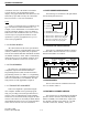
Ceramic Bandpass Filter Wide/Narrow Band Switch Ceramic Bandpass Filter Ceramic Bandpass Filter Wide/Narrow Band Switch FI4 D15/ D16 FI5 FI6 D13/ D14 RF UNIT W/N LOGIC UNIT Wide/Narrow Band Select 450 kHz Second IF 44.775 MHz Second Injection RECEIVER Bandpas Filter RF Amp Q1 FI1 Bandpass Filter FI2 Audio Amp RECEIVE AUDIO PROCESSING Bandpass Filter IF Amp FI3 DET Second Mixer/Detector Q2 IC3 Rx Freq Minus 45.
R26 C41 R27 J1 MIC JACK R96 C27 R32 R33 R24 C44 C2 C43 R23 C37 C1 D4 Q7 HC5 HC14 R25 C38 R21 C33 HC17 C36 R22 C34 L34 L13 D15 R91 Q14 R104 C7 R92 HR1 D10 R102 C32 FI4 R77 C29 C111 HC2 HC6 FI1 C50 GND R39 R1 C49 L5 C122 C5 C40 D16 C8 C9 Q1 R20 C47 R95 L14 C138 R2 Q6 C48 HC3 Q5 R37 FIOUT C46 C31 L32 C4 R3 Q19 C45 C137 W/N Q20 Q21 R35 R36 HC9 R34 D11 D3 R30 L2 C30 W1 FI7 C42 L1 R29 D2 D1 R31 D5 R28 C35 C140 IC2 HC2
RF5V REGULATOR 1 2 3 6 VIN 5 GND 4 VOUT CONT GND N.BYPASS 100K R14 100 R16 IC1 LIMITER/SECOND MIXER/DETECTOR 0.1 C18 47K R15 TK11350BM C8 0.1 C3 0.047 CPV REGULATOR R25 C4 10 R17 330K HC1 C SQUELCH 2.2K 6 VIN 5 GND 4 VOUT CONT GND N.BYPASS 2.2K R27 R12 6.8K C33 Squelch Adjust 2SC4081 Q1 VCOV 4.7K R2 10 2 C5 0.001 1 0.001 C12 0.01 C13 0.01 CDBCA450CX24 0.01 X1 R8 2.7K C15 R21 100K 180 RECEIVER IF BOARD C26 33P C19 0.001 C10 ERJ3GE-JPW WIDE 0.01 0.
On-Off Volume Control C140 C123 Q106 C408 Q402 C403 C139 C142 R145 C136 C307 R160 R319 R313 IC305 D306 IC114 R321 IC309 TO ACCESSORY JACK R408 W9 D301 R312 D104 R304 R310 D105 R317 To DC Power Flex Circuit W8 C305 R318 C304 C27 C303 HC3 R127 C301 R316 R303 R311 C28 C118 C137 J2 C157 C158 1 C111 D103 R314 D305 Q301 R315 D302 Q107 9 C144 C33 R148 C145 R336 R147 D312 C113 C402 C138 IC104 C29 R337 D310 R149 R118 R119 R326 R120 C115 Q302
RECEIVE AUDIO PROCESSING BATT LVCC R5V R167 Q111 NPSPAC DTC144EE R101 390K 0.01 C101 W4 150K R103 47K ERJ3GE-JPW W/N 5 3 8 2 IC101A 4 47K C102 470P R102 100K 2 3 1 R104 Q110 1 0.039 C104 0.001 R106 56K RX_OUT RX_IN LEVEL ADJ R107 R108 27K 560K R105 120K R165 47K +5V R133 R135 8 R134 100K C127 R136 47K 3 7 0.0022 C128 IC102A MC33172D 2 4 C125 0.01 0.0033 C141 C17 0.01 R153 33K C IC110 8 7 6 5 DET SN_TR R150 1 2 3 4 R151 1K R152 1K R154 5 7 10K 3.
MIC MICE GND GND BKLED L5V GND GND SP SPE 1 2 KEYS3 KEYS2 KEYS1 KEYS0 GND KEYR1 KEYR0 GND KEYR3 KEYR2 GND GND SPE SPE SP SP L5V DISSO DISSK DISST DISEN KEYS0 KEYS1 KEYS2 KEYS3 KEYR0 KEYR1 KEYR2 KEYR3 TXLED BSYLED BATLED BKLED GND MICE MIC GND GND GND DS6 R2 DS1 DISPLAY BOARD BOTTOM VIEW November 1999 Part No.
SCHEMATIC DIAGRAMS AND COMPONENT LAYOUTS TX LED BUSY LED 2SA1576 2SA1576 R12 1K DS3 2SA1576 R13 47K CCCS SSSSSS SSSSS SSSSS 2 1 3 3 3 2 2 2 2 2 2 1 1 1 1 1 8 7 4 3 2 1 8 7 4 3 1 0 9 6 5 2 1 2 1 1 1 1 1 1 1 1 1 1 0 9 8 7 6 5 4 3 2 1 0 9 8 7 6 5 4 3 2 1 Q3 Q2 R11 47K C5 33P BATTERY Q4 R14 1K CCCSSSSS SSSSSS SSSSS S 2 1 3 3 3 2 2 2 2 2 2 1 1 1 1 1 8 7 4 3 2 1 8 7 4 3 1 0 9 6 5 2 1 R16 820 R15 47K SSSSSSSSSSSS CCC3 3 3 2 2 2 2 1 1 1 1 1 SSSS S 4 3 1 3 0 4 9 6 5 2 8 7 4 3 0 9 1 6 5 2 DS5 DS4
SCHEMATIC DIAGRAMS AND COMPONENT LAYOUTS 1 (PHON) 2 (STR) 3 (HOME) 5 6 SYS (RCL) DS2 D S4 4 GRP (CLR) 7 (S.A/D) 8 9 3 DS DS1 0 * ( SCAN (SND) # ) HC1 R4 R2 HC4 HC3 R5 R3 R12 R11 HC8 C5 2 20 HC7 J1 Q1 R10 L5V BKLED GND GND SPE SP GND GND MICE MIC 1 19 HC11 HC12 HC2 KEYS2 KEYS3 KEYR0 KEYR1 KEYR2 KEYR3 GND HC5 HC6 GND KEYS0 KEYS1 10-KEY BOARD FRONT VIEW HC9 HC10 C4 C3 C2 R1 C1 MICROPHONE SPEAKER 10-KEY BOARD BACK VIEW November 1999 Part No.
SCHEMATIC DIAGRAMS AND COMPONENT LAYOUTS MC1 Microphone R1 33K C1 33P C2 33P SP1 C3 33P Speaker C4 33P R2 R3 100K 100K R4 100K R5 100K S13 HC5 C 1 S1 2 S2 3 S3 F1 S14 4 S4 5 S5 6 S6 S8 9 S9 F2 S15 HC6 C 7 HC7 C HC1 C GK NE DY S 0 K E Y S 1 K E Y S 2 K E Y S 3 KKKKG EEEEN YYYYD RRRR 0 1 2 3 * S7 S10 8 HC2 C 0 HC3 C S11 # S12 F3 HC4 C HC8 C R12 Q1 2SA1576 10K 2 1 1 1 1 1 8 6 4 2 0 8 6 4 2 0 C5 J1 AXN720535 33P 1 1 1 1 1 9 7 5 3 1 9 7 5 3 1 R10 120 R11
SCHEMATIC DIAGRAMS AND COMPONENT LAYOUTS DS2 A/D ( ) DS1 SCAN MENU HC3 HC2 R4 R3 R2 HC1 R8 R6 C5 HC4 HC5 HC6 3-KEY BOARD FRONT VIEW 2 20 HC8 HC7 J1 1 19 Q1 C4 C3 C2 R1 C1 MICROPHONE SPEAKER 3-KEY BOARD BACK VIEW November 1999 Part No.
SCHEMATIC DIAGRAMS AND COMPONENT LAYOUTS MC1 Microphone C1 33P R1 33K C2 33P SP1 C3 33P Speaker C4 33P R2 R3 R4 100K 100K 100K HC1 C F1 HC2 C HC5 C GK NE DY S 0 K E Y S 1 K E Y S 2 K E Y S 3 HC6 C HC7 C S1 F2 S2 F3 HC3 C S3 HC4 C HC8 C KKKKG EEEEN YYYYD RRRR 0 1 2 3 R8 Q1 2SA1576 10K 2 1 1 1 1 1 8 6 4 2 0 8 6 4 2 0 C5 J1 AXN720535 R6 220 33P 1 1 1 1 1 9 7 5 3 1 9 7 5 3 1 DS2 LN1371G-(TR) S S G G + B G G MM PPNN5 KNNI I E DDL L DDCC E E D DS1 LN1371G-(TR) 3-KEY BOARD
SCHEMATIC DIAGRAMS AND COMPONENT LAYOUTS NOTES November 1999 Part No.
Part No. 001-7780-500 11-99hph Printed in U.S.A.