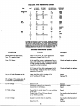
4 WATT HIGH FIDELITY POWER AMPLIFIER MOD E L HF·14 A INSTRUCTiON MANUAL E L E C TRDNIC 330 D NORTHERN INSTRUMENT CO. BLVD., l. J. BITT Iffw-•• £,,1', OT '/UI"nl'A' -A .>'Y. W. f!A,,;,t "II( :7"" :F. ~.> W•. ~~.. ...+- INC • ". 1.
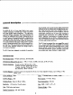
general description chClJ"Qctertsti~ under speaker load (Including electrostatic types) as well as the resistive load normally used for testIng. Phase eerreetlens have been provided at both extremes of the audio spectrum to insure stability under all conceivable eendltlens and to insure that variations in components and constnJctlon wi II not affect the performance. Stability is maintained on all speaker taps with loads rongingfrom zero to infinity.
mechanical In.hlilation GENERAL 0) HEAT DISSIPATION (VENTILATION), Ineemecnwlth ,9ther electronic equipment; the Model HF-14prbduees a gr8c;rt deal ofhed I" normal operation. Unle.. conttn~ uous and adequate air- flow I, obtained around the heat pr'Oducfngelements,these. elementswill overheat and their usefulllfewlUbegreatlycurtalled. Adequateventllation will be provided I' the ampllfler·I, JrlItOlledln CIl openbackconsoleprovlded,that the topaf the ~ltfJer Ii spaced at lealt two Inchel'belbw any ,h.
, the terminal with a number equal to h" of one of the speake"', rated Impedance. (It maylJe necessary to "'phole II the two speakers by revening bollao' the leads from one of the speakers.) This may not lie do.. if each of the speakers Is designed for reproduction of a different part of the audio spactum (woofer-tweeter' c:ambinations), In which case a cross-over network k required which conneets to the amplifier with only a. pair of leads.
...In"n...ce __ ...... _ ~_ CONTILOL ADJIISTMENTS 0) The INPUTLEVELADJ. conlloll.ln.ended to protect the system from"ubICllting" should lOIMOne tum the preampllfler-eontrol unit level control. to full, by pe..... milling 1"" to attenuate.he preampllfl.r aulput .Ignal by OoY"'lrod amount at .he Inpu' to.he power amplifier where It can not be "fiddled" wlth~ Start by..ttlng the INPUT LEVEL maximum ccxnter--cloclcwl.. (maximum at.. tenuatlon~ using a screwdriver.
VOLTAGE AND RESISTANCE CHART -,"'" V, "H' I 2 , .U , • , .U • •, 7 8 .... ...va 1 2 7 8 .. 118' V' 2 a .U • • DC VOlTS NO SIGNAL DCVOUS l.4WAm ...".• ...• ACVOLTS (1 kc) 1.DVOLTS INPUT ,. '112 ". 0 ,~. " f l l - ' (6.3VAC b.twee) '"• ,., ,., '.OKlI •••" ••• •••., , • •• ,_..., •.s f11_nt ". • ""''' ...... -.. '"'' ...... • .." I......" '.S ,-.." '" '" '" '" f11_t (6.3VAC be'--) '" 7 8 ..., 510KD I." 1.13 fJI-m (6.
REPLACEMENT PARTS LIST Stock' ~ Description 22S29 CI cap., dIIC., lSOmmf, cap., diIC., • 025m1d -500V (25K or 2S, 000) ",,0' dllc., 2OOmmf, *10'*. 225" C~5 22539 C" C. 23007 22533 2.011 c' C' C, """" " 9100II SIlO" SIIOI6 JI J~3 ='0% cop., ,te"., 5Omfd-25V c•• , dl,c., 471l1'f1f, *10% cap., .I&C., 3O-~20mfd-450V cap., paper, .03mfd-600V fuse, 2....." 10cJc, Iinlill. phono outlet, ODItVO'II.n~ 97032 J6 lack,. octal 18050 RI pot., 500KQ, audio 10400 U.S-IO ..... , 10lCQ,.
~ _~scrif.l~jon Rl1 Ltf-l C7 V R3'l: J1 I I ::S.5 :::E R6 -4 CI I C2 R2 \~~3.1. , ~' RI~ - I I .. RIO RB ... R9 R13 Rl.4 :c Z CBC . ~ .'5 * - R7 T1 II t ~9 I~ l~ .~~ Fl I I L lack, sl1l81e phono outlet, c:onvenlence outlet, l:onvenience lack, octal pot.; SCIOKO, aud!o ros., lOKQ, 1/zw, .1~ res., 470KO, I/ZN, :1:10% res., 1.8KQ, 1/2N,:I:,5% res., 10KO, 1/211, :l:109b res., 100m 1(2W, :I:: 5% res., l00KO, 1/'lW, :I:: 5% res., 33OKO, 1/211, :1:10% res., 33OKO, I/ZW, :1:10% tel.
s ~ · N ~ ~ · .-. . !~"H ·· -o c-. n _ .. • 1; .0 .. ! - ~ ................ _0 ~ " .0 - " r n .... " ~ •• ,• l ;~ ."" p,;;: -.- ., 0 ". 0 ' ,. ., ,..-._. • c .-.'•• ,-.0 -z -, , ., .' 0,0 0- • ~ s •• • ,• • 0< , • " ~~ ...nO'" ... :: ' ,. .. ., ,-ff ~!.0. -·,•• ., co- :~ :::~ I ! 0 0- ., 0:'" ,"j> •• .'• " "•• • ~ ,•l ", ... PI •• ., o .-.,-.• • :;;! .' _0 .., 0- ,-, g -,• ,0 , , , • ~ ~, ,•• • .' ! .. ?;;; ,• p ~b o.o.
The section of the manual be inning with this page is the CONSTRUCTION section. All poges in this se tion hev e page numbers followed by "C" nc, 2e, ete .}, The INSTRUCTI N section resumes on the pages following the CONSTRUCTIONsection. N fe that the CONSTRUCTlONseetion is located centrally in the book and ma be remov ed without desruptlng the INSTRUCTION leetlon that both preces it and follows it. dered with the tip of a pair of 10ngn05e pliers.
• -.. ->x '" I - ;;: 00 U 2.
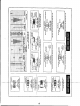
TOP OF CIHASSIS MOUNTING When the JeexU on the transformptrs are too long, cut them to the size indicated in the steps below. In each ~c+' after cutting the leads to the specIfied size,. ~ strip back 1/4" of the outer j~ulation so that the bare wire shows, Then tin the wire by dipping the strippe{l end into a solder pot, or melting solder onto the wire with a hot soldering trbn. 1. ( ) Fig. 1. On the power t former 12, 30019, cut both red leads to 3", the redoor-llow and whit.
l -..... ... N co 4C ..
REAR CHASSIS MOUNTING 1. ( ) Fig. 2. Mount the foufcrew terminal board Tal, from the outside of the chQlli. QI shown. Us. two 6-32lcrews and two '6-32 hex nut. Under one hex nut, mount a '6 groun lug. Under the lecond hex nut, mount a one post right terminal strip, r&2, nd a '6 lockwasher. I 2. () Fig. 2. Mount the pcbtentiometer Tl, as shown. Us. one 3/81ockwasher and one 3/8 hex nut. i '(!: anr 3. ( ) Fig. 2. Mount the InLtlack J I, as .hown (Fig. 4).
..
FINAL CHASSIS ASSEMBLY 1. ( ) Fig. 3. On the side of t~e cheul. mount the sUcie switch S1, os shown. (Fig. J,). Use two 1J,-.40 screWs, two IJ, lockwcahe" "'" two'4 hex nuls. -I 2. ( ) Fig. 3. Moun. fuseholder XFl ca shown. Use large rubber wcaher (1\ outside the chassis. ngh'en to "hOllis with hex nut supplied. Do not 'ighten too much or holder will crac:k. 3. ( ) FIg. 3. Moun t t he tube sockeh' XV2, XV3, and XVJ, ca ........ (fig. J,). Use two '4-40 screws, two '4Ioc!ewe.
-$TBl Rll C7 TB2 XV3 R1 )1 )4 )2 )3 51 00 1"' -, "8.
WIRING 1. ("""--Flg. 4. Connect a 1" piece of bene wire from Tll-! (C) to ground lug itA U (S l). 2. (Io)""fi~. 4. From output trans~onner TI,COMect the black [ecd to D1-1 (S2), tho brown lead 10 TSI-2 (51), t a yollow lead 10 181-4 (C) ond the brownyellow lead to XV3-7 (51). T lst the blue and red leads together. Connect th...d load 10 XV2-9(C)and I a blueleed toXV2-7(51). COMOct the groon I..d to T81-3(SI). (~. 4. ~m 4. (,rFle· 4. Cut both leads o~ a 47 ....f disc capocllor, C7, to 3/4".
• TB2 (4 XVl XV3 (6 (5 Rl (1 R10 XV2 R13 R2 R3 J1 TB3 R5 J4 R15 XV4 J3 -o ('> I R9 (2 R8 R12 R6 (3 TI14 R7 ~ • Fig_ 5 R4
1. (,;{FI9. 5. Connect a lug "C" {St} on socket J4. 3/4" piece of bare wire from J4-3 (51) to ground 13. (""Fig. 5.· Cut both leads on (I 10KO: (brown, block, orange, sliver) re- slster, RS, to 1/2". .Ccnneet rrom T83-.1 (53) to T83-2 (52). ~. 2. 5. Cut both lead! on a 6800 Iblue, grey, brown, silver) resistor, RISt to 3/4". Cover each lead,with a 1/2" piece of spaghetti. Connect from XV4-3 (52) to J4-4 (51). ' 3. (".+19g.5. Connect a 4 1/2' piece of black wire from TB2(S3)toXVl-3(C). (~.
FINAL STEPS You have now completed th OIsembly and wiring of your amplifier. When you have completed the folio Ing steps your amplifler will be ready for use. this p-.:~pose. Ii t he \,mplif'€7 is to be fastened to a surface, the feet will not be used and the bottom plate will be required as a template before It is attached to the amplifier.