
Instruction manual


The section of the manual be inning with this page is the CONSTRUCTION
section. All poges in this se tion heve page
numbers
followed by "C" nc,
2e,
ete
.}, The
INSTRUCTI
N section resumes on the pages following the
CONSTRUCTIONsection. N fe that the CONSTRUCTlONseetion is located
centrally in the
book and ma be removed without desruptlng the INSTRUC-
TION leetlon that both
preces
it
and follows
it.
Core taken In the
conSfructlFf
this Instrument will reward .the constructor
with
many
yecmofSCltisfactory.
lee
and greaterconfidence
'0.
his instrument.
We
urOe
you
to not rush the -nstruction, but to take all the time necessary
for proper
assembly and wlrln .
Furthermore, we urge
stronglY~at
youfollow the wire and parts layout shown
in the pictorial diagrams as
cI Iy as possible. Very often wires are placed
as shown for a good
reaton, nd certolnly the appearan.ce of the completed
Instrument wIll beimprov
edan
thedlfficultyof finding a wiring error will be
reduced by the following
the ire and parts layout shown.
UNPACKING
THE
KIT:
un
1
'
k the kltcarefully and check each portogotnst
the
partslht
Ineludingthese rts that are rnountedto the
chanls.
If you have
trouble Identifying any
ports r fer to the pictorial diagrams or the color code
,;;
chart.
You will find that the value
1.
a component will
...
ary within the allowable
circuit tolerance. For exampl , the
4.7KO,
:t:
10%
resistor may measure any-
where between
4.2KO and 5. KO. Tolerances on paper capacitors are sub-
stantially greater, and the to
erence
for electrolytics is usually +100% and
-50%.
•
CONSTRUCTION
HINTS,
U E
TME
BEST
GRADE
OF
ROSIN
CORE
SOLDER
ONLY,
prefeTClbly
one cont, tnlng the new activated fluxes such as Kester
"RI.ln-Ftve",
Ersln
"Multlca II or simllcrrtyp
...
UNDER
NO
CI~CUMSTAN
CES
USE
ACID CORE SOlDE OR ACID
FLUX
since acid flux can cause
se-
rious corrosion. Before
sold.
tng make a certain of a good mechanical
cen-
nectlon. U.e a
clean,
freshly Inned soldering Iron, no smaller than 100 watts,
and place the solder on
the 1 nt (not on the Iron)so that the lolder Is melted
by the heat
from
the iolnt
ttl
If. Do not remo
...
e the soldering Iron until the
solder fiowl and cheek to
se.
at
th&resultlng joint Is
smoe:th
and.Mny when
the solder hal
cooled. There are two extremes to be av
olded~
too little heat
<WId
too
much
h.at. If
too
lit I. h.at
IlllJpplled,
th'lalnt willapp.arpitted
and grey, lndleoting a restn I int which isunsatllfoctory. On the other hand,
if too much
heat
it
applied a Joint, the parts connected to
it
may either
change v
alu.,
loose their pra ctl.... coating, or break down. If you
or.
sol-
der1ngclos. to a
port, hold th lead between the port and the Joint being
101
...
dered with the tip of a pair of
10ngn05e
pliers. The pliers will conduct the
heat
away and prevent the componell,t from being unduly overheated. If for
any reason
it
11
necessary to reselder a joint, be sure to use new solder.
It should also be noted that the lead's on resistors, capacitors, and transformers
are often
longer than required. These leads should be trimmed to
the
proper
length when necessary. Do not
cut
(my lead until
you
have detemilned
the"
required length when the
leOd
11
rout-ed
c.
shown In the
diogrOOlS.
BASIC
TOOLS
REQUIRED:
These basic tools are required for the construction,
of the amplifier.
1. Screwdriver - 3/16" to 1/4" blade
2. Screwdriver - 1/8" blade
3. longnese pliers - 5 or 6"
4.
Dlaeonal cutters
5. Soldering lron (100 watts), or soldergun, or penell Iron (35 watts)
6. Gas pliers
7.
High quality rosin or equl
...
alent synthetic flux core solder. D0!!2! use
ccld
or paste flux under any circumstances.
A set
at
spintites and a wire stripper are also
ve~
useful supplemeri'tiiry tools:-
PARTS
IDENTIFICATION: Please note that very many
of
the parts:'forwhich
color coding Is given maynot be
celer
coded, but have their
...
aluesarid ratings
:,rinted. 'the letter J(' Is a multlpller(Xl000) and on reslston or capacltoti
in-
dicates that the printed numerical vclue must be multiplied by one-thousand
to obtain the value in ohms or micro-micro farods respectl
...
ely.
Not.-
a'lso
that
one microfarad (mf) is equal to one "lillian; mlcro-microfaradl
(mmf}r
To
-old
in rapid 1dentification, keep in mind that 5%, 10%, and 20%
....
rifort,'a
...,
color coded whereas 1% resistor have their values printed; also thaf molded'
tubulat capacitors mayor may not be color coded, whereasdtlc capacitors and
electrolytlcs will
alwQyJ
hQVe
their "Qlu
..
printed.
PloOlo
note the following
relationships
between the units used to
expres.s
resistance or
capac'ty.
1,000,000
ohm.
(0)
= 1000 kilohm.
(KO):
1
megohm
(Ma)
1,000,000
micro-micro farad.
(mmf)
os
1 micro 'orack (rnf)
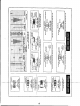
CONSDUCTlQN
PRCX;EDUREj
Thecomplete step-by-step mountingand
wir-
Ing proctc:lure foilowi. Tokecp ""edrllW1ngsuncrowdtc:l, unnecenory repetition <
01
mounting
or
wirIng
d.tail.
may
~,.
omltt.d.
Nol"
Th.
abbrtVlallon'(I:"
means connect but do not soldeduntil other leedt ha.... been connllcfed),-'The-
abbrevlatlon (5) means connect and solder,
Bend the ground lug tabs on the sockets toward' the chassis to prevenhJcc-ldeil---
tal shorting to the seeket pins.