
Instruction manual


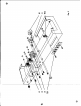


TOP
OF CIHASSIS
MOUNTING
1. ( ) Fig. 1. On
the
power t
former
12, 30019, cut both red leads to
3",
the
redoor-llow
and
whit.
I to 2 1/2
11
and the two green leads to 3 1/2".
Donot
cut
the remaining leads Mount the power transforme, all shown, with
the g,een
leads
clos
..
t to the s de of the
chossis
(Fig.4&5).
Use
fou,'Siock-
wQlhen and four
'8-32
hex n ts, Under one
of
the
lockwashers, mount a
'S
ground lug as shawn in Fig. 4.
When the
JeexU
on
the
transformptrs
are
too long,
cut
them to the
size
indicated
in the steps below. In
each
~c+'
after cutting the leads to the specIfied size,.
strip back 1/4" of the outer
j~ulation
so that the bare wire shows, Then tin
the wire bydipping
the
strippe{l end into a solder pot,
or
melting solder onto
the wire
with a hotsoldering trbn.
~
2.
()
Fig. 1.
On
the
output transFormer 11, 32005,
cut
the green lead to
3
1/2",
the yellow lead to 1
1/2
11
and
the blue lead to 4
1/2".
Do
not
cut
the
remaining leads. Mount
the
output transformer as shown with
the
brown
end
the
yellow leads closest to the rectaneiJlarhole in the stcleofthe chassis
(Ag.4
& 5). U.e fou,
'S
lockwaohen
and
fou,
's-32
hex
nuh.
3. ( ) Fig. 1.
Mount
the 9 pin mlnloture tube socket with shield support,
XVI,
as
shown.
Note direction in
Fin.4.
Use
two
'<4-40
screws,
two
'41ock;;'
woshers and two
,~
he~
nvh.
4.
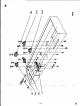
()
Fig. 1. Mount
electrolytic
eon copacTtor,C8, OJ shown.
Note
~
moan,
aquar.
and
trlangl.
MClr
lu.
to
d.termlne
direction
ofmountl"l (PlI.4).
Insert
the
mounting
tabs
into the slob in the
chcasis
and twist the
.some-
what
Ie"
than a quarter
tum.
DO NOT twist the tabs excessively or they
wUJ
shear off. Solder
the tab
without a hole to the chaNls
at
Its
slot.