
Instruction manual


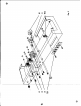


FINAL CHASSIS ASSEMBLY
1. ( )
Fig.
3.
On
the
side of
t~e
cheul.
mount
the
sUcie
switch S1, os
shown.
(Fig.
J,).
Use
two
1J,-.40
screWs,
two
IJ,
lockwcahe"
"'"
two'4
hex nuls.
-I
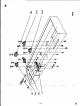
2. ( )
Fig.
3.
Moun.
fuseholder
XFl ca
shown.
Use
large
rubber
wcaher
(1\
outside
the
chassis.
ngh'en to
"hOllis
with
hex
nut supplied.
Do
not 'ighten
too
much
or
holder
will
crac:k.
3. ( )
FIg.
3.
Moun
t the tube sockeh'
XV2, XV3,
and
XVJ,
ca........ (fig.
J,).
Use two '4-40
screws,
two
'4Ioc!ewe.hen
and
two '4-40 hex
nuts
-an
each.
4. ( )
Fig.
3.
Mount
the
two
post
'·_Inal
baard
TB3,
and the
....,
post
......
mlnal
board,
1M
as
shown.
Use
one
'6-32lcrew,
one
'6Iockwasher.-d0Nl
'6-32 hex nuton each.