
Instruction manual


1.
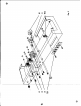
(,;{FI9.
5. Connect a
3/4"
piece
of bare wire from
J4-3
(51) to ground
lug "C" {St} on socket
J4.
2. ~. 5. Cut both lead! on a
6800
Iblue, grey, brown, silver) resistor,
RIS
t
to
3/4".
Cover each lead,with a 1/2" piece of spaghetti. Connect
from
XV4-3
(52) to J4-4 (51). '
3. (".+19g.5. Connect a 4
1/2'
pieceof black wire from
TB2(S3)toXVl-3(C).
4. (6W'ig. 5. Connect a 3" pi ce of black wire fromXV3-3 (C) to XV2-3 (C).
5. (U"'FIS. 5. Cut both
lea
on a
SOmfd
electrolytic
capacitor, C6, to
3/4".
Cover both leads with
CI
/2"
piece
of spaghetti. COMect the negatIve
H I,nd to
gn>Und
lug
"0"
(5I) ot
XV20nd
the positive lend
(+)
toXV3-3(52).
6.
(~F1g.
5.
On
the
165Qwir
wound resistor, Rl2, cut one
lead
to
3/4
11
and
the second leod to I
1/2".
Co er the shorter
lead
with a
1/2"
piece
spaghetti
and connect
to XV2-3 ($2).
Meet
the
longer
lead
to ground Ius
"Ell
(51)
on
can capacitor,
ca.
Solder he
Sl'Qund
lug liE" to the chassis at this point.
=:
7.
r,,;r
FlliJ.
5. Cut both Ie • on
Cl
100KQ (brown,ltlack, yellow, gold)
S96
("
r.lstor,
R7, to
3/4".
Cover e ch lead with a
1/2"
piece spaghetti. Connect
f",m
XVI-B
(C)
to g",und
lug'
F" (C) ct
XV3.
8.
c,..r1lg.
S. Cut both
lea
on a 200nvnf disc capacitor, C4, to
3/4".
Cover each lead with a
1/2"
p
ace
of spaghetti. Connect from
XVl-8
(C) to
gn>und
lug"F"
(52)
ct
XV3.
9. (
~.
5. Cut both leads
or
a •025mfd (25K or 25,
OOOmmf)
disc
capaci-
tor,
CS,
tc 3/4". Cover
'cch
Ilecd
with e 1/2"
pile,
of
spCQh,ttl.
Connect
frem
XV1·8
(53) to XV3-8 (C)
10. ("y1rg. S.
Connect
Q
l'
piece
of bare wire covered with a
3/4"
piece
of .poghetti
frcm
XVI-I (C) to XVI-7 (51).
11.
(~Ig.
5. Cut both I I S on a 470KQ (yellow, violet, yellow,silver)
resistor, R3,
to
1/2".
Connec from XV1-I (C) to T83-1 (C).
12.
{J(flg,
S.
Cut both I
ds
en clSOmmfdl.c ccpecltor,
CI,
to 3/4".
Caver one
l.ad
with a
1/2"
p
ece
of spaghetti
Q/"Id
connect to
XV1
..1 (53).
Connect the other
lead to T83 2 (e).
13.
(""Fig.
5.·
Cut
both leads on
(I
10KO:
(brown, block,orange, sliver)
re-
slster,
RS,
to 1/2". .Ccnneet
rrom
T83-.1
(53) to T83-2 (52).
14.
(~.
5.
ctt
both leads on a'1.
8KO:
(brown,grey, red,gold) resistor,
R4,
to 3/4". CoMect from XVI-3
(S~)
to T84-2(C).
15.
<tI1lg.
S. Cut both leads on a 2)()mmf dIsc capacitor, C3, to JlI, Cover
one lead with a
3/4"
piece of spagheUI and connect to
XVl-6
(e). Connect
the other leod to T84-2(C).
16.
(,,"Fig.
5. Cut both
leods
on 0 looKll (b",wn,block,yellow,gold) 5%
r
..
l.tor,
R6,
to 1/2".
COMeet
&om
XVI-6
(C)
to
T84-1
(52).
17.
(~5.
Connect a I" pIece of bare wire
from
potentiomete~
Rl-3(SI)
to
JI-I
(51). ;
18. CH'"'Flg. 5. Cut one
lead
on a 10Ke: (brown, black, orange, silver)
re-
sistor, R2, to
1/2"
and connect XV1·,2 (51). Cut
the
other
lead
to 3/4" and
connect to potentiometer
Rl-2
(51).
19.
(~.
5. Cut both lead. on c.I)2Smfd (25Kor25,OOOmmf)
di.a
capaci-
tor, C2, to 1
1/4".
Cover
each
leae! with a 1"
piece
0'
spaghettI. Connect
f",m
XVI-6 (53)to
XV2-B
(C).
20.
(~g.
5. Cut
all
leads on two 10Ke:(bro:.m.,
black,
orange, silver)
resistors,
RIO
and R13, to
1/2".
Connect
RIO
from XV3-8 (e) to XV3-2 ($ 1).
Ccneect
RI3
frcm
XV2-8
(C)to
XV2··2
(5
I).
21. <,.JA!Ig. .5. Cut all leads on two
33OKO
(orange, oronge, yellow, sliver)
re.i.toll,
R8
end
R9,
to 1/2". Conn,ct
R8
fromXV3-B
(53) to
ground
lug "G"
(51) at XV3. Connect R9 from
XV2~8
(53) to ground
IUIi
"H" (51)
at
XV2.
22. (/f'1'lg. 5.
Push
the tinned solder leod.
frem
the line cord
thn>ugh
the
grommet on
the
rear apron of the
chcJS$js,
next to
J3.
Tie a knot in the line
cord 1
1/2"
from the tinned solder le'ads so
that
the
cord
eannot
pull through
the
grommet. Connect one solder lead
toJ3-2(53)and
the second solder lead
to J3-1 (52).
23.
Vf1g.
5.
Conneeta
4
1/2"pleceofblackwlrefromJi-2(C)toTB4-2(S3).
24.
(~lg.
5. Connect a 1 1/2"
plet:.
of black
wlrefromJl-2
(52) to Rl..1(51).