
Instruction manual


FINAL
STEPS
this
p-.:~pose.
Ii t he \,mplif'€7 is to be fastened to a surface, the feet will not
be used and the bottom
plate
will be required as a template before It is
attached
to the amplifier.
SERVICE
B)
Read
the
MECHANICAL
INSTALLATION
and
ELECTRICAL
INSTALLATION
sectionsof the Instruction book
carefully,
and install
and
connect
the amplifier
according to the Information given.
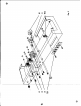
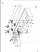
Fig, 6
You
have now completed th OIsembly and wiring of your amplifier. When
you have completed
the
folio Ing steps your amplifler will be ready for use.
1) To
catch
any
wiring erron,
it
is suggested
that
the
entire
wiring be checked
polnt--by-point against the wi ing instructions (and preferably also against the
schematic wiring diagram In 0 der to become more famtliar with the component
layout
and'circuitry).
While doing so, check for rosin Iolnts, loose lumps of
solder, poor lead dress,
and
a cidental shorts or leakage paths arising from
the
flow of rosin between
conta
ts (remove with a stiff brush dipped In carbon
tetrachloride).
2) Clean
socket
XVl with
c~rbon
tetrachloride using a stiff brush.
It
is also
advisable to remove the
tube
land shield from XV1, and
clean
the socket
and
pins on top of the chassis.
~
3)
Insert
tubes VI through
v4
in their correct sockets and the
fuse
in the fuse
1\
holder. Place a shield
over
V1.
4) Insert
the
octal
plug into
~ctal
socket
J4.
6) Press a speed nut in
place
oyer
each
hole on
the
bottom flange of the chassis
(see F;g. 6).
nIf the amplifler is not
goin~
to be fastened to some surface, insert the rubber
feet
in
the
openings provided in the bottom
plate
and mount the bottom plate
of the eh
...
;" u.ing 3
'8-32
r3/B" mew>. De not use the 1"lang
screws
fa'
5)
IMPORTANT,
BE
SURE
TO
BEFORE
CONNECTING TO
at
least 3 ohms across the
AI
between ground and pins 1 CIl'l'
ohms between pin 3 of
the
re
for the electrolytie
cepeelte
last measurement. These me
power supply components
and
taln these resistance values,
discovered
CI'ld
the condition
proceed to step 6.
KE
THfFOLLOWING
RESISTANCE
CHECKS
EAC LINE: Check for a cold dc resistance of
plug; chock for a rEilistance of
at
lead
85 ohms
7ofXV4;cheek
for a resistanceof at leest
lOOK
ifier tube V4
and
ground. AlloWsufficient time
to be charged by the ohmmeter
battery
in this
;uremenb constitute a
reClSOnable
check
of
the
iring before applying power. Ifyou fail to
cb-
not
proc~d
to the
next
step until the
cauie
is
eedled,
If
the
measurements are satisfactory,
If you
are
still having difficulty,
write
to our servtce deporhnent lilting all
possible indications
that
might
be
helpful. If desired, you may return the
in-
strument to our factory where it will
be
placed
in operating condition for S
5.00
plus the cost of ports replaced due to rlieir being damaged in the
coune
of
con'tructton.
This service poltey applies only to completed instrumenb-con"
structed in accordance with the instructions as stated in the man-ual. Instru-
metlb
that
are
not
completed
orinstrumenh
that
are modified will
not
be
ac-
cepted
for
repair.
Instrumenb
that
show
evidence
of
acid
core solder or paste
flux.s
will be returned not
repaired.
NOTE: Before returning this
unit,
be
sur.
all
pam
are securely mounted. Attach a tag to the instrument, giving
your home
addreu
and
the trouble with
the
unit.
Pack very carefuHy
ina
rugged contaIner, using sufficient packIng material
(cotton,
shredded news-
paper,
or excelsior), to make the unlit completely immovable within
the
con-
tainer.
The original shippIng corton is satisfactory, providing the original
insem
are
used or sufficient packing material is inserted to keep the instru-
ment immovable. Ship by prepaid Railway Express, If possible, to the
Elec-
tronic Instrument
Co.,
Inc
.•
33-00
f'lorthern
Blvd~
l.I.C.
I,
New York. Re-
tumshipmentwiH be madeby express
collect.
Note
that
the
carrier cannot be
held Iiabl e for damages in transit ifpocking, IN HIS
OPINION,
isinsufficlent.