
Instruction manual


mechanical
In.hlilation
GENERAL
0)
HEAT
DISSIPATION
(VENTILATION),
Ineemecnwlth
,9ther electronic
equipment;
the Model HF-14prbduees a
gr8c;rt
deal
ofhed
I"
normal
operation. Unle
..
conttn~
uous and adequate air- flow I, obtained around the heat
pr'Oducfngelements,these. elementswill overheat andtheir
usefulllfewlUbegreatlycurtalled. Adequateventllation
will
be
provided
I'
the
ampllfler·I,
JrlItOlledln
CIl
open-
backconsoleprovlded,that the topafthe
~ltfJer
Ii spac-
ed
at
lealt
two Inchel'belbw
any
,h.lf
mounted aboVe it.
if the cabinet is
enci~ed
at the rear, provide several large
hoI
..
or slots eli low
clown
and as 'high'up In the cabinet
back
CIS
poalble.
AI
~
altemate,
hoi.
may be provided
In the
sid.,
bottom,or
top
of the cabinet. Thelmportant
thing to remember Is that
effective
ventJlatlon
requires
provisionfor
cool
oir to eriter
at
the
bottom
and
to
leave
at
the top. .
._.
If the ampUfier Is not Installed In a console, It should
be
situated preferably on. an open surface. An
attractively
ftni.hed
matchIng
cover
forthe
Mod.1 HF
...
14 is
available
which will
provide
a
"flnllhed
lt
appearance
as well CIt
protection
when
the
amplifier
itnotlnstalled
In a
console.
Four
rubber
feet
are
also
provIded
10
that
the
amplifier
will
not
mar
the
suri'ace
of
fumiture
on
which
it
is
placed.
b)
ACCESSIBILITY
TO
PARTS:
Tubes
are tho
moot
fre-
quently
replaced
Items
In
electronic
equipment.
If
the
amplifier
II
placed
in a console,
sufficient
space
should
be
allotted
to
reach
and
remove
ony
tube
In
the
ampli-
fier. Furthermore, Input and
output
terminals
of
the
am-
plifier
should be
accessibl.
to
permit
e<lSy
interchanging
of
system components
far
comparison. If
antennas
are
strung
around
the
back
of
the
console In
which
the
ampli-
fier
is
Installed,
arrange
them so
they
will
not
interfere.
c)
ELECTRICAL
ISOLATION: To
realize
thefull
benefit
of
having
a power
ampllfl.r
physically
separate
from
the
preampllfJer'"'COi'ltrol
unit
and/or
tuner,
the
power ampll..
fter
should
be
placed
at
least
one
foot
away (more
ifpos.
sible)
from
either
or
both
of
these units. '
d)
ACOUSTICAL
ISOLAnON: If
ampun.,
and speake,
are
Install.d
In
the
same
cabinet,
provide
sufficient
sep-
aration
to minimize
mechanical
speaker
vibration
reaching
the
amplifier.
The minimum
separation
Is
about
onefo:ot.
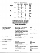
CONSOLI
MOUNTING
Having
determlned
a
proper
location
for
the
OffFlifler In
the
partlcularconsole,
the
correct
procedure
for mounting
the
amplifier
chaaiJ
b as follows:' a) If
the
rubber
feet'
have
been
imerte<! in
the
bottom
plate,
remove them
(pry
out
with a
thin
screwdriver). b) Remove
the
6
sc~
which
fastenth.
bottom
plate
to
the
chassis.,
c)
Place
th.
bottom
plate
(bumps
facing
up) at
the
location
on
thuhelf
or
other
mounting
surface
In
which
It
is
de.lred
to mount
the
amplifier.
With a sharp
pencil,
placed
with
its point
directly
agaInst
the
edge of
the
lower
surface
of
the
bot-
tom
plote,
draw
the
outline
of
the
bottom
plate
on
the
shelf
and
also
marie
the
positions
of
the
four
outer
holes.
d) Remove
the
bottom
plate
and drill
each
of
the
marked
holes
an.
the
shelf
to a
diameter
of
1'4".
e)
Refasten the
bottom
plate
to
the
chassis
l
with
2 8 x
3/8
screws pre-
viously
removed,
using
the
holes at
the
center.
f) Re-
place
the
chouls
on
the
shelf,
positioning
It
exactly
In
the
outline
previous!y drawn. 9) From
the
bottom side
ofthe
shelf,
insert a 'B x
l"screw
with
a
1/2
10
flat
washer
against
the
head
through
each
of
the
four holes. These
screws
engage
thestarnped
nut
over
each
hole
In
the
chouls
flange
and
when
tightened
secure
the
chassis to
the
shelf.
electrical
in.tallatlon
_
POWER
A)
POWER
REQUIREMENTS,
Ihe
EICOMcxleI
HF-14
re-
quires 65
watts
at
110 to 120
volts,
60
cyeles
AC.
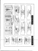
b)
REMOTE
SWITCHING,
Tho
EICO
Model
HF-14,
al-
though
not
privlded
with
its own
ON-OFF
power
switch,
lIasp1oyislon faa
lemoleswltchhly,llllwgl,
OIloclol
socket
mounted
on
the
chassis. Pins 6
and
70f
the
octal
socket
are
Internally
connected
to
the
ends
of
a break In
one
power transformer primary
lead
mid
are
externally
con-
nected
togetharbya
[umper In a
mal.
octal
plug
Inserted
In
the
cetelseeket,
WhM this male
plug
is removed, pins
6 and 7 may be brought
out
to an
external
AC
switch,
usually in a
preamplifier
unit.
This Is
oneofthe
connect-
Ionfunctions
accomplished
with
the
octal
plug-and-cable
attached
to
the
EICO
HF-65A and HF-61A
preamplrner-
control
unit.
If
the
HF-14
power
amplifier
Is
being
wed
with a
self-powered
tuner-preampllner,
the
octal
fur-
nished
with
the
HF-14remains Inserted In
the
octal
socket
(to
connect
the
primary
of
the
power transformer to
the
AC Ifna
and
10 ground
on.
side
of
the
filament
winding)
and
the
line
cord
«
the
HF-14
is Inserted in a switched
117VAC
convenience
outl.t
In
the
control
unit.
Note:
When using a self-powereel
preamplifier-control
unit,
touch
one
end
of a
wire
to
the
preampl1fier chassis and
the
other
enel;
at
the
pewer
amplifier
ehessls.
If
Q sperk
a)
POWERING
AUXILIARY
PREAMPLIFIER,
The
.ame
octa.lsock,t
provldn
QII
neconaty
filament
and
B+
vel-
ta;elfor
operatln;
an
CIIxIIIQ"Y
preomplifl.r"'COntrol unit.
6.3
yolts
I.e
fllam'nt
volta;., at I
ampere,
may
be
ob-
tained
from
~Ins
1
a,ld
2,
pin
number4
on
the
socket
sup-
plies
~y.lh
DC,
at
a
mcudmum
current
of 10
mtlli-
omperell
anel
pin 3 is
GOMected
to
ground.
~
stated
abov.,
cont~1
a'
117volh AC line
power
to
the
power