
Instruction manual


INTERCONNECTION PROCEDURE
* If the preamplifier requires 350VDC, use pin
4;
If the
preamplifier requires less
than
35UVDC.
use
pin
5 and
connect
a dropping resistor
of
oppoprlalevolue
and
'101-
toge rating from pin 4 to pin
50f
the
octal
sockets
on
the
HF
14
ehassiso For eHampl.,
if
tha
~
..
lifi_
in
queat-
Wired HF-65A preamplifiers wtll have the preamplifier
leads
connected
to
the
octal
plug as in the
table
above.
c) If It Is desired to use a
p~if'"
..
r without 0 power
supplyotherthan
the
HF-61Aor
HF-65A.;tfle
power
tab-
off
leads
of
the
preamplifier should
be
connected
to the
HF-14
octal
plug
(after
removing the
iUllp8rs)-
follows:
, the terminal with a number equal to
h"
of
one
of
the
speake"',
rated
Impedance.
(It
maylJe
necessary
to
"'phole
II
the
two
speakers by
revening
bollao'
the
leads
from one
of
the
speakers.)
This may
not
lie do
..
if
each
of
the
speakers Is designed for reproduction
of
a
different
part
of
the
audio
spactum (woofer-tweeter' c:ambinations), In
which
case a cross-over network k required which con-
neets to
the
amplifier with
only
a.
pair
of leads.
Pin
of
Octal
Plug
Connected
to
6
7
I
2
4
3
Pin
of
0cIa1
Plug.
Com.dod
to
6
7
1
2
40r
5"
3
Color
of Preamp. Lead
grey
ll'ey
brown
brown
red
black
Preamp. Power
lead
AeON-OFF
AC ON-OFF
filament
(6.3VAC)
fHament
(6.3VAC)
B+
ground
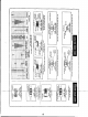
a)
Make
all
system Interconnections
bebe
applying
AC
power. Making or breaking
interc:olVledions
while
AC
power is
applied
will result in a .:Imentary
overload
of
both
the
power
amplifier and specliaersysilm wiih possible
dornage to
either
or
both.
b) If
the
EICO HF-65A preampllflwcontrol
unit
(not self-
powered)
has
been
obtained
In kit
form"
remove
011
the
jumper connections In the
octal
plug
.."plied
with
the
HF-14and
wire
the preamplifier
pcJWer
take-off
leads to
this plug as follows:
d)
CONVENIENCE
OUTLETS,
When
the HF-14 Is
used
with a preamplifier
that
takes power from it,
weh
as the
EICO HF-65A, the
convenience
outlets of
the
HF-14will
be found useful.
Theoutletmarked"117VAC
SH.
II
("SW."
Is on abbreviation for "SWITCHED
It
) Is
"lIve
lt
or
"dead·
depending on whether
the
preampltfJer power switch Is
turned to
ON
or OFF; plug tuners Into the
outlet.
The
outlet
marked "117VAC" Is not switched
and
Is
"live"
whenever the HF-14
line
cord plug is Inserted In a wall
outJet; plug a record
changer
Into this
outlet
in
order
to
protect the mechanism. When
the
HF-14 Is used with a
self-poweredpreamplifier,
such as
the
EICO HF-6SA,
nor-
mally the
convenienceovtlats
on
the
preamplifier wfIJ be
used. However, the HF-14
outlets
may be used also, if
desired, In which case both of them will be "switched".
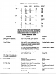
INTERCONNECTION OF COMPONENTS.
SIGNAL
0)
PREAMPLIFIER-CONTROL
TO
POWER
AMPLIFIER,
Single conductor,
shielded
coble must
be
used to
inter-
connect
the preampllfter-eontrol
unit
or
tuner-preampli-
fier-control unit and the power amplifier. Unless the
source has a low
impedmce
outlet,
such as a cathode
follower (with which up
to SOft.
of
cable
can be used),
use
the shortest possible connection; In
any
cose,use a low
capacity
type
of
shielded
cable
(os10wOl2S mmf
capacity
per
foot is
available).
Both ends
of
the
cable
must be
fitted with
RCA
type phono plug connectors.
amplifier,
andlndlrectly,
power for
the
precimpllffer-con'"
trol unit,
Ibelf,
is made
available
through
the
connectiOns
to pins 6 and 7. This arrangement Ii
exactly
suitable
for
powerlngthe.ElCO
HF-6.$4, and HF-61Apreampfifler-eOn-
trolunit;all
that
need
be
done
Is to remove
the
octal
plug
provided with the
HF-14
from
the
octal
socket
and
Insert
the
octal
plug-and-cobleaf
the HF-65A In its stead.
Note
that
a Jumper between pins 2 and 3 of
the
octal
plug
fur-
nished with the
HF-14effectively
grounds
one
side of the
filament winding; removal of the
octal
plug leaves the
filament winding
floating.
This arrangement is used
be-
cause 0 hum
balance
control is connected
acrou
the
fila-
ment leads In
the
EICO HF-65A preamplifier and
the
arm
of this control is returned to ground.
b)
SPEAKER
CONNECTIONS:
To
connect
your speaJcer
to the amplifier properly, you must know its
rated
Imped-
ance,whlch
Is usually marked on
the
speaker or specified
In
the
manufacturerls literature.
Connect
one
speeker
lead to
the terminal on
the
rear apron
marked
"G"and
the
olhe. speake. lead
10 the newby lanllinal desIgnated
b,
If
It
is desired to use
two
similar or Identical
full-range
speakers of the some
rated
Impedance(eltherBor
160hms
only) for
better
sound distribution,
connect
one
speaker
lead
of each paIr to
"Gil
and the two remaining leads to
ion requires 300VDC
B+voltage.10
..
draln,thedrop-
ping resistor will be required
tothp
....
voltage
by
SO
volts (350-300 =
SO)
at
a
current
oflOrnlL
Brehm1slaw,
the required resistance Inohms Is the
vollage
drop
in
volts
divided
by
the
current
in amperes
or50
wlts,l.
01 GIIIp. =
5000
ohms. The power dissipated
in
the
resistor in watts
is
equal
to
thevoltoge
drop
in
volls rnuftipfied by
the
cur-
rent In amperes or
SO
volts x
.OI~=O.5wotts.
For
safety
a resistor
of
double
the
woItage
rating
should be
used. Therefore, a
5000
ohm I
watt
resistor is required.
3