Eiconcard™ Connections for Linux User’s Guide www.dialogic.
Copyright © 2000-2009 Dialogic Corporation. All Rights Reserved. You may not reproduce this document in whole or in part without permission in writing from Dialogic Corporation at the address provided below. All contents of this document are furnished for informational use only and are subject to change without notice and do not represent a commitment on the part of Dialogic Corporation or its subsidiaries ("Dialogic").
• You may transfer the Program, documentation and the license to another eligible party within Your Company if the other party agrees to accept the terms and conditions of this Agreement.
U.S. Government Restricted Rights The Program and all accompanying documentation are provided with RESTRICTED RIGHTS. Use, duplication or disclosure by the U.S. Government is subject to restrictions as set forth in subparagraph (c)(1)(iii) of The Rights in Technical Data and Computer Software clause at DFARS 252.227-7013 or subparagraph (c) (1) and (2) of the Commercial Computer Software-Restricted Rights at 48 CFR52.227-19, both as applicable.
Eicon Connections for Linux User’s Guide Contents About this Guide ........................................................................................... 5 Typographic Conventions ............................................................. 6 Introducing Eiconcard Connections for Linux ........................................... 7 The Eiconcard Connections for Linux Solution ................................. 7 The Eiconcard ............................................................................
X.29 Call User Data Format ........................................................................ 75 Key Packet Formats .................................................................................... 77 Call Request Packet Format ......................................................... 77 Call Accepted Packet Format ....................................................... 78 Clear Request Packet Format ....................................................... 79 Clear Confirmation Packet Format .......
Eicon Connections for Linux User’s Guide CHAPTER 1 About this Guide The Eiconcard Connections for Linux User’s Guide provides information on how to configure and use Eiconcard Connections for Linux. It includes the following sections: Important: This document does not contain information on how to install Eiconcard Connections for Linux. For installation information, consult the Release Notes (ReadmeFirst.txt) located in the Linux/SC_Series directory on the Universal Connections Suite CD.
About this Guide 9: X.29 Call User Data Format Provides the format for the X.29 Call User Data. 10: Key Packet Formats Provides the formats for all the key packet types. 11: X.3 PAD Parameters X.3 PAD parameters set the guidelines for how the PAD deals with different terminal emulations. Typographic Conventions This document uses the following typographic conventions: Normal italic type is used for filenames, pathnames, and program names. Mono-spaced type is used for commands and parameters.
Eicon Connections for Linux User’s Guide CHAPTER 2 Introducing Eiconcard Connections for Linux This chapter introduces Eiconcard Connections for Linux. It provides an overview of the Eiconcard Connections for Linux architecture and describes the communications options it offers. It also provides a brief description of Dialogic’s hardware solution—the Eiconcard—and its supported communications protocols.
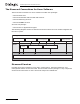
Introducing Eiconcard Connections for Linux The Eiconcard Connections for Linux Software The Eiconcard Connections for Linux software includes four packages: • Eiconcard Services • Eiconcard Host PAD and Terminal PAD Services • Eiconcard Routing Services • Eiconcard SNMP Services And one sub-package: • Eiconcard X.25 Application Support The following diagram shows how the Eiconcard Connections for Linux module integrates into the Linux system.
Eicon Connections for Linux User’s Guide The Eiconcard Host PAD and Terminal PAD Driver The PAD Driver architecture consists of the Host PAD and Terminal PAD drivers running on top of the Eiconcard driver. These drivers fully emulate tty drivers, so any asynchronous application written to tty driver standards can function with the Linux PAD drivers. Eiconcard Host PAD Driver The Eiconcard Host PAD driver allows remote users to access your Linux server over X.25 connections.
Introducing Eiconcard Connections for Linux The diagram below illustrates how the Terminal PAD driver and Host PAD drivers are used in a typical installation. TCP/IP or SPX/IPX network Terminal PAD TPAD Eiconcard ASCII Terminals telnet or nvt users X.25 link ASCII terminals use the Terminal PAD and Eiconcard to access geographically remote hosts concurrently. X.
Eicon Connections for Linux User’s Guide Eiconcard SNMP Services This package provides the necessary support for network management. It allows the user to remotely control and monitor the Eiconcard Services components. As a remote manager you can perform real-time administrative tasks, gather statistics, and track the router's performance.
Introducing Eiconcard Connections for Linux OSI Support Eiconcard Connections for Linux is implemented according to the OSI model. The top layer— the Application Layer—is implemented by the PAD Support components or applications developed using the Eiconcard Development Tools. The Network Layer and Data Link Layer are implemented respectively by the X.25 and HDLC protocol support provided by the Eiconcard Services package.
Eicon Connections for Linux User’s Guide For More Information The Eiconcard Connections for Linux Release Notes provides step-by-step instructions for installing the Eiconcard Connections for Linux product. The remainder of this user’s guide provides information on configuring and operating Eiconcard Connections for Linux.
Introducing Eiconcard Connections for Linux page 14
Eicon Connections for Linux User’s Guide CHAPTER 3 Configuring Eiconcard Connections for Linux Installing/Removing Eiconcard Connections for Linux This section describes how to install the Eiconcard Services and Eiconcard Connections for Linux software. Introduction The Eiconcard Connections for Linux software is installed using rpm. You must be logged in as ROOT in order to install and configure it.
Configuring Eiconcard Connections for Linux ECCLI Method The Eiconcard Command Line Interface (ECCLI) application can be used to configure the routing services and automatically generate the routing services configuration file (mpr.if). Refer to the ECCLI documentation for details. Manual Method Optionally you can manually create and modify the mpr.if file in /opt/dialogic/c4l. For details on the mpr.if file and how to configure a router for your Eiconcard(s), see the documentation and samples.
Eicon Connections for Linux User’s Guide Removing Eiconcard Services To remove the Eiconcard Services, do the following: # rpm -e Eiconcard_Services Manually removing /opt/dialogic/c4l (optional) To completely remove all Eiconcard software and directories from your system after removing the packages with "rpm -e ...
Configuring Eiconcard Connections for Linux 3. Select the Eiconcard you wish to add from the displayed list of Eiconcards which are present in the system but not installed. The status of Eiconcards which are not installed is listed as UNINSTL. 4. Press Enter. 5. If you want to add another Eiconcard now, repeat steps 2-4. Otherwise, enter b to go back to the main Eiconcard Configuration screen Uninstall an Eiconcard To uninstall an Eiconcard run eiconcfg and follow these steps: 1.
Eicon Connections for Linux User’s Guide High-Level Services Eiconcard Connections for Linux High-Level Services consists of the following options: • Transport ISO • Routing Services • Compression Modules. Follow these steps to configure the Eiconcard High-Level Services: 1. Execute /opt/dialogic/c4l/eiconcfg 2. Select option 4, Configure Eiconcard Protocols. 3. Press F4 to access the configuration screens. 4. Move the cursor to the desired High-Level Protocol and press the Spacebar to enable the feature.
Configuring Eiconcard Connections for Linux • SIG.+X.25 Choose one of these options based on the line type or modem being used. Changing Protocol Parameters Each protocol has a number of parameters associated with it. These parameters allow customization of the protocol software for your particular connection. Eiconcard protocols can be configured to suit almost any communications situation. This is done by assigning values to the parameters in the protocol configuration screens.
Eicon Connections for Linux User’s Guide Note: If you are unable to use either set of function keys, consult the administrator’s guide for your Linux operating system for information on keyboard mappings. Function Key Description F1 Help Provides information about the current screen and its parameters. F2 Save Saves the parameter values for all screens to the configuration file. F3 Prev Moves you to the previous configuration screen, if applicable.
Configuring Eiconcard Connections for Linux 9. Specify a value for the Static TEI parameter and press F1 for details on configuring the D-channel to transfer X.25 packet data. Note: For the NI-1 switch type, you must also specify the X.25 DTE address before you can access the online help. Configuration Procedure The eiconcfg program stores most parameter settings in the Eiconcard configuration file. The default name for this file is /opt/dialogic/c4l/ec.cfg.
Eicon Connections for Linux User’s Guide 14. Enter q to quit eiconcfg or, if you want to configure any of the Eiconcard Connections for Linux drivers, do not quit eiconcfg now. Instead, proceed to the relevant configuration section outlined in this chapter. Configure Advanced Options The default parameters for the Advanced Driver Options should be suitable for most user systems. However, you may want to increase these values if your system includes multiple applications written with the Eiconcard X.
Configuring Eiconcard Connections for Linux To install or remove the Eiconcard Host PAD driver, follow these steps: 1. Execute /opt/dialogic/c4l/eiconcfg 2. Select option 6, Configure PAD. 3. Select option 1, Eiconcard Host PAD Driver Configuration. 4. Select option 2, Install/Remove the Eiconcard Host PAD Driver, as desired. 5. Select an option or press Enter to continue. 6. Enter q to return to the Eiconcard Host PAD Driver Configuration screen. 7.
Eicon Connections for Linux User’s Guide CHAPTER 4 Using the Eiconcard Host PAD and Eiconcard Terminal PAD This section explains how to prepare and test the Eiconcard Host PAD devices and includes the available stty settings for the Eiconcard Host PAD tty devices and their equivalent X.3 PAD parameters. It also provides information on configuring the Eiconcard Terminal PAD using the cu and uucp commands. For more information on X.3 PAD parameters, see X.3 PAD Parameters on page 81.
Using the Eiconcard Host PAD and Eiconcard Terminal PAD Maintaining X.3 Parameter Profiles tpadprof tpadprof tpadprof tpadprof -h [name...] [-x parameters][-s comment][-P profile][name...] -r [-P profile] name... Information about all of these commands are available online. For information on how to access these commands, using an HTML browser, see For More Information on page 13.
Eicon Connections for Linux User’s Guide Testing Eiconcard Host PAD Devices Once the system has been rebooted and is running in multi-user mode, you should test an Eiconcard Host PAD connection as follows: 1. Load the Eiconcard manually if it is not already loaded: # eccard start 2. Issue the eccard status and hpad commands to verify that the port(s) assigned to your Eiconcard Host PAD tty devices are active. Use the hpadcfg -p command to reconfigure the devices if necessary. 3.
Using the Eiconcard Host PAD and Eiconcard Terminal PAD The Eiconcard Terminal PAD driver is used to make outgoing uucp calls. The uucp configuration files must be set to your specific requirements before you make a call. For information on configuring these files, see The uucp Configuration Files on page 31. To modify the outgoing call, use tpaddir with a conn command or use the cu CALL command. X.28 is a CCITT recommendation that defines the messages that a terminal can send to a PAD. The X.
Eicon Connections for Linux User’s Guide Examples *call *call *call *call *call 324576 092341 /1,1 324543123 /1,0,2,1 /"login" 234512343 // "uucp" 34657332 /1,0 /-1,0,0,1,"bill" clr Clear virtual call. If no virtual call is established when this command is invoked, the error message No connection is displayed. *clr conn name Connect to given name. The name is a PAD directory entry that describes the called DTE, its X.25 address, the facilities, the call-user data, and the X.
Using the Eiconcard Host PAD and Eiconcard Terminal PAD port [port] Set physical port. This command sets the physical port on which the communications will take place. Normally, ports 1-255 are used. If you do not specify a port, the current port number is displayed. To re-assign a port, include a decimal number with the port command. This PAD command signal is provided as an extension to the standard PAD recommendation. *port 1 *port 2 *port 2 prof [profile identifier] Set X.3 Profile. Set the X.
Eicon Connections for Linux User’s Guide reset Reset virtual circuit. If no virtual call is established when this command is invoked, the error message No connection is displayed. *reset set [par:val,par:val...] Set the specified X.3 PAD parameters (par) to the specified values (val). If no par:val is specified, the PAD parameters are set to the value of the current profile identifier. If a specified parameter reference and/or value is invalid, it is displayed with its value specified as inv.
Using the Eiconcard Host PAD and Eiconcard Terminal PAD Examples are used to help clarify how these uucp configuration files are used. Names and other user-supplied items are chosen arbitrarily. To run these examples on your system, choose user-supplied names and items that are defined for your system. The uucp configuration files are usually located in the /etc/uucp directory. Check your Linux documentation on uucp for the correct path on your system.
Eicon Connections for Linux User’s Guide *call 1302056300026 // Call remote system or use *conn host1 //host1 must be have been previously defined using the tpadddir command * Connected // Connected to remote system Welcome to ... login: xxxxx // Login to remote system password: ***** $ // Now in remote system $... $... // Perform desired work $...
Using the Eiconcard Host PAD and Eiconcard Terminal PAD page 34
Eicon Connections for Linux User’s Guide CHAPTER 5 Using Eiconcard Routing Services This section describes the steps necessary for establishing routes in Eiconcard Routing Services. It describes the key protocol configuration parameters for Eiconcards, and tests a sample X.25, Frame Relay, PPP, and Multilink PPP link. This chapter also explains how to use the connection backup feature. Overview To operate Eiconcard Routing Services, you must perform the following tasks: • Configure the mpr.
Using Eiconcard Routing Services The circuit entries you define for Routing Services are bound to the Routing Services call-directory entries, depending on availability. Only when the circuit entry is associated with a call-directory entry can you attempt to establish a connection. Routing Services then allocates an open subnetwork circuit to the call-directory entry as needed during the connection.
Eicon Connections for Linux User’s Guide Configuring Packet Filtering Rules When Routing Services receives an IP datagram over an interface, it checks the configured packet filtering rules, and transparently forwards or drops the datagram based on these rules. It is important to note that adding packet filtering will affect the performance of Eiconcard Routing Services. As each IP datagram has to be tested against all of the defined packet filtering rules, the datagrams will be delayed.
Using Eiconcard Routing Services Parameters Description -dport [dest_port] Specifies the destination port for which you are specifying a packet filtering rule. All packets with a destination port that matches a port specified in the packet filtering rules are either forwarded or dropped. A destination port is specified to prevent access to certain services or applications on a remote system by local hosts. This option must be enclosed within the brackets.
Eicon Connections for Linux User’s Guide When you use the route command, entries are added directly to a host’s IP-routing table, but will be lost when the system shuts down. If you are setting up a complex network, it is recommended that you use the TCP/IP routing daemon, which is initialized with the entries stored in the host’s /etc/gateways file. The routed daemon manages both static and dynamic routes, updating all hosts and gateways in the network automatically.
Using Eiconcard Routing Services In this case, Sys-2 functions as a gateway to the 192.218.20 network. Make sure each routing table entry you add to a host’s /etc/gateways file is correct before adding another entry. You may want to test the route connection, as routed will not inform you of any errors in /etc/gateways, such as an incorrectly specified IP address. Note: If changes are made to the /etc/gateways file, the routed daemon must be restarted with the -s option.
Eicon Connections for Linux User’s Guide You may assign your own IP addresses for this test, but it is recommended that you use the IP addresses suggested in Resources for the Test System below. The Test System The test system described here links two Linux systems together back to back through their Eiconcards. This procedure also tests the connection backup feature. Although this setup cannot be considered an internetwork, it tests the Eiconcards’ transmission and reception of IP datagrams over an X.
Using Eiconcard Routing Services To test the back-to-back connection, including the connection backup feature, you need to configure the two Eiconcards, define an Eiconcard Routing Services circuit on each system, define the destination IP addresses for the circuits on each system, and define the backup circuits on each system before you can transmit data using the connection.
Eicon Connections for Linux User’s Guide 10. Run eccard start on both systems. The Eiconcards on each system are loaded and configured according to the parameters found in their ec.cfg file. Once eccard start has run successfully (no errors reported), you can use ecstatus to check the integrity of the connection between Sys-1 and Sys-2. Note: If you start the DTE first, it will report an error even though the connection will be properly set up once you start the DCE.
Using Eiconcard Routing Services the circuit or the mprstat -cv command to display detailed status information for the circuits if necessary. For more information on the ecstatus command, see ecstatus.html in the /opt/dialogic/c4l/docs directory. 3. If all the circuit states are set properly, go ahead to Testing Sys-1/Sys-2 Communications on page 51.
Eicon Connections for Linux User’s Guide 7. Once the parameters are set, press F2 Save and F10 to exit. The two ec.cfg files are now configured for Sys-1 and Sys-2’s back-to-back connection. 8. If the Eiconcard is already loaded and running (using eccard start), run eccard stop to stop it. 9. Connect the Eiconcard in Sys-1 to the Eiconcard in Sys-2 with an RS-232 null-modem cable. 10. Run eccard start on both systems.
Using Eiconcard Routing Services Setting Up a PPP Connection You can set up a Point-to-Point connection using Sys-1 and Sys-2 by following this procedure. 1. Select the Eiconcard Services Protocol Configuration option in eiconcfg on each system to modify its Eiconcard configuration. 2. At the Hardware Configuration screen, set auto activate ports to No for the PPP ports. 3. Move to the Protocol Configuration screen. Select Routing Services.
Eicon Connections for Linux User’s Guide 16. Run ecstatus ppp to confirm that the link between Sys-1 and Sys-2 is operational. The Protocol State item appearing in the left column of the ecstatus display should be listed as “Opening” on both systems. Check that the circuit is correctly defined on both systems and that the two circuits are bound by using the mprstat -c command.
Using Eiconcard Routing Services 7. On Sys-2, set the password authentication parameters as follows: Local PAP User Name Local PAP Password Remote PAP User Name Remote PAP Password System2 Pass2 System1 Pass1 Local CHAP User Name Local CHAP Secret Remote CHAP User Name Sys2 Password Sys1 Important: If these parameters are not configured correctly on both sides of the connection, the circuits will not start. 8. Press F3 twice to return to the Protocol Configuration screen.
Eicon Connections for Linux User’s Guide 19. Run ecstatus ppp to confirm that the link between Sys-1 and Sys-2 is operational. The Protocol State item appearing in the left column of the ecstatus display should be listed as “Opening” on both systems. Check that the circuit is correctly defined on both systems and that the two circuits are bound by using the mprstat -c command.
Using Eiconcard Routing Services 9. On Sys-2, set the local directory number to 384020 and the remote directory number to 384000 on both port 1 and port 2. Note: These numbers are used only for the purpose of this example, and should be replaced by your ISDN number. 10. Once the parameters are set, press F2 Save and F10 to exit. The two ec.cfg files are now configured for Sys-1 and Sys-2’s connection. 11. If the Eiconcard is already loaded and running (using eccard start), run eccard stop to stop it. 12.
Eicon Connections for Linux User’s Guide Testing Sys-1/Sys-2 Communications The two systems are now ready to exchange IP datagrams over the X.25, Frame Relay, or PPP link that connects them together. The TCP/IP ping utility provides a convenient way of doing this. The ping utility provides real network traffic by means of ICMP Echo Requests. It transmits datagrams from one system to another system identified by the specified IP address.
Using Eiconcard Routing Services page 52
Eicon Connections for Linux User’s Guide CHAPTER 6 Advanced Eiconcard Services Configuration This section describes the advanced Eiconcard Services Configuration. Eiconcard Device Driver Parameters Total Request Buffers Allocated The Total Request Buffers Allocated parameter defines the number of request buffers to be allocated for the Eiconcard Streams Device Driver. Request buffers are used to transfer commands between the Eiconcard Driver and the Eiconcard.
Advanced Eiconcard Services Configuration Load/Self-test Timeout Period The Load/Self-test Timeout Period parameter is the maximum time in seconds that the load/self-test procedure is permitted to take before assuming that a system hardware or software failure has occurred. Watchdog Wake Up Period This parameter serves to monitor the Eiconcard Character-Compatibility Driver’s usage of resources.
Eicon Connections for Linux User’s Guide CHAPTER 7 Modem and Null-Modem Cables This section describes the modem and null-modem cables available from Dialogic and how to use them. It also includes diagrams showing the pin-out wiring and signals for each cable, as well as instructions for making null-modem connections between two systems. Connecting Two Workstations This section describes how to connect two Linux servers, each with an Eiconcard, back-to-back using a null-modem cable.
Modem and Null-Modem Cables Establishing Contact The diagram below summarizes the proper configuration of hardware and software for a null-modem connection. Server A Server B Null-Modem Cable Configuration: - DCE - Internal Clocking When in the terminal emulation software, first set one workstation to ANSWER, and then the other to CALL mode. Configuration: - DTE - External Clocking To make a back-to-back X.25/HDLC connection using a null-modem cable, follow these steps: 1.
Eicon Connections for Linux User’s Guide Modem Cables This section contains information, including pin-out diagrams, on all Dialogic modem cables. All current modem cables for Eiconcards are shown in the table below. These cables may be ordered from your Dialogic distributor. Cable Name Part Number V.24 Modem Cable 300-007 V.35 HSI Modem Cable 300-024 X.21 HSI Modem Cable 300-025 V.24 HSI Modem Cable 300-026 HSI/V.
Modem and Null-Modem Cables All connectors specified in the following diagrams must have a shielded ground. Small boxes around the wires denote a twisted pair. For complete wiring diagrams, contact your Dialogic representative. Note: The V.24 Modem Cable, the V.24 HSI Modem Cable, and the HSI/V.24 Converter are fully symmetrical.
Eicon Connections for Linux User’s Guide DB-26 Male DB-25 Male DB-15 Male DB-26 Male 1 PGND 7 SGND 9 S(A) 10 S(B) 11 R(A) 12 R(B) 13 I(B) 16 I(A) 14 B(A) 23 B(B) 19 T(A) 26 T(B) 20 C(B) 24 C(A) NC 1 8 6 13 4 11 12 5 7 14 2 9 10 3 15 1 2 3 4 5 6 7 8 15 17 18 20 21 22 24 25 PGND TxD RxD RTS CTS DSR SGND DCD TxCLK RxCLK TEST DTR RLB RI CLK TI 1 2 3 4 5 6 7 8 15 17 18 20 21 22 24 25 V.24 HSI Modem Cable 300-026 X.
Modem and Null-Modem Cables All connectors specified in the following diagram must have shielded ground. Small boxes around the wires denote a twisted pair. For complete wiring diagrams, contact your Dialogic representative.
Eicon Connections for Linux User’s Guide APPENDIX A X.25 User-Facility Support and Code References This section describes X.25 user-facility support features and includes details on DNICs, X.25 diagnostic and cause codes, and ASCII control codes specific to the X.25 protocol. User-Facility Support User facilities are optional network services that let you perform tasks such as reversing charges on your calls, accessing a Closed User Group, or specifying a Network User Identification (NUI).
X.25 User-Facility Support and Code References * The Fast Select facility code is present in the incoming call packet if reverse charging and/or fast select is indicated. Facility Types Facilities fall into two groups: those specified at subscription time, and those specified on a per-call basis. Subscription Facilities The first group includes CCITT facilities such as nonstandard default window and packet sizes, Closed User Group definitions, barring of incoming or outgoing calls, and reverse charging.
Eicon Connections for Linux User’s Guide User Facility Code Closed User Group (CUG) Selection 3,CUG index Flow Control Negotiation (packet size) 42,insize,outsize Flow Control Negotiation (window size) 43,insize,outsize Network User Identification (NUI) C6,NUIlength,NUI Packet size The packet size for transmissions from the remote DTE is shown in the low nibble of the first octet in the parameter field.
X.25 User-Facility Support and Code References Window sizes of 1 to 7 are standard. Window sizes of 8 to 127 are valid only if extended sequence numbering is used. The default window size is 2. A value of 0 is not allowed. Fast Select The fast select facility is controlled by bits 6 and 7 of the octet in the parameter field. If fast select is not requested then bits 6 and 7 are set to 0. If fast select is requested with no restriction on response then bit 6 is set to 0 and bit 7 is set to 1.
Eicon Connections for Linux User’s Guide The two groups of four bits referring to throughput class are binary coded and indicate the throughput classes as follows: Throughput Class Values Remote DTE Local DTE Throughput (bits/s) 0 0 0 0 0 0 0 0 Reserved 0 0 0 1 0 0 0 1 Reserved 0 0 1 0 0 0 1 0 Reserved 0 0 1 1 0 0 1 1 75 0 1 0 0 0 1 0 0 150 0 1 0 1 0 1 0 1 300 0 1 1 0 0 1 1 0 600 0 1 1 1 0 1 1 1 1200 1 0 0 0 1 0 0 0 2400 1
X.25 User-Facility Support and Code References CUG with Outgoing Access Selection The index number to the closed user group selected for the virtual call is in the form of two decimal digits. Each digit is coded in BCD, in a nibble of the parameter field. The high nibble represents the first digit and the low nibble represents the second digit.
Eicon Connections for Linux User’s Guide Bits 1, 2, 3, 4, 5 may be used for other facilities or set to 0 Note: The reverse charging and Fast Select facilities share the same facility code and may be used concurrently. Network User Identification (NUI) The octet following the facility code field indicates the length, in octets, of the Password and NUI fields. The following octets contain the user password and network user identification.
X.25 User-Facility Support and Code References Networks and DNICs CCITT Recommendation X.121 defines a general address format containing 12, 13, or 14 digits. The first four digits of a general address format constitute the Data Network Identification Code (DNIC). The first three digits of the DNIC generally identify the country— much like telephone area codes—with the exception of large countries such as the United States. The fourth digit identifies a particular network within the country.
Eicon Connections for Linux User’s Guide Country Network DNIC Israel Isranet 4251 Italy ITAPAC 2227 Jamaica Jamatel 3380 Japan (NTT) DDX-P 4401 Japan (KDD) Venus-P 4408 Luxembourg Luxpac 2704 Malaysia Maypac 5021 Mexico Telepac 3340 Netherlands Datanet 1 2044 Norway Datapak 2422 Panama Intelpaq 7141 Portugal SABD 2682 Puerto Rico UDTS-PDIA 3301 Singapore Telepac 5252 South Korea DNS 4501 Spain Iberpac 2145 Sweden Telepak 2402 Switzerland Telepac 2284
X.
Eicon Connections for Linux User’s Guide Description Diagnostic Hex Code Invalid called address EX25ICDA 0x43 Invalid calling address EX25ICGA 0x44 Invalid facility/registration length EX25IFRLEN 0x45 Incoming call barred EX25ICBARRED 0x46 No logical channel available EX25NLCAVAIL 0x47 Call collision EX25CALLCOLL 0x48 Duplicate facility requested EX25DUPFACREQ 0x49 Non-zero address length EX25N0ADDRLEN 0x4A Non-zero facility length EX25N0FACLEN 0x4B Facility not provided when e
X.
Eicon Connections for Linux User’s Guide 13 CR Ctrl-M or Enter 14 SO Ctrl-N 15 SI Ctrl-O 16 DLE Ctrl-P 17 DC1 Ctrl-Q 18 DC2 Ctrl-R 19 DC3 Ctrl-S 20 DC4 Ctrl-T 21 NAK Ctrl-U 22 SYN Ctrl-V 23 ETB Ctrl-W 24 CAN Ctrl-X 25 EM Ctrl-Y 26 SUB Ctrl-Z 27 ESC Esc or Ctrl-[ 28 FS Ctrl-\ 29 GS Ctrl-] 30 RS Ctrl-6 31 US Ctrl- - 127 DEL Del page 73
X.
Eicon Connections for Linux User’s Guide APPENDIX B X.29 Call User Data Format An overview of the Call User Data formats used in X.25 calls is provided in this section. It shows how to format user data for X.25 call clearing. The format for Call User Data consists of four protocol identifier octets followed by a maximum of 12 octets of the call user data. Octets consist of bits numbered 7 to 0, where bit 0 is the low order bit and is transmitted first.
X.
Eicon Connections for Linux User’s Guide APPENDIX C Key Packet Formats Details of the Packet Format for the X.25 Packets used in call establishment and call clearing are provided in this section. It describes the fields that must be filled by the application. Call Request Packet Format The format for a Call Request Packet is shown below. Octets consist of bits numbered 7 to 0 where bit 0 is the low order bit and is transmitted first.
Key Packet Formats Call Accepted Packet Format The format for a Call Accepted Packet is shown below. Octets consist of bits numbered 7 to 0 where bit 0 is the low order bit and is transmitted first. Octets are consecutively numbered starting from 1 and are transmitted in this order. The General Format Identifier can be coded 0x01 for modulo 8 or to 0x10 for modulo 128. See the CCITT X.25 Recommendation for details.
Eicon Connections for Linux User’s Guide Clear Request Packet Format The format for a Clear Request Packet is shown below. Octets consist of bits numbered 7 to 0 where bit 0 is the low order bit and is transmitted first. Octets are consecutively numbered starting from 1 and are transmitted in this order. The General Format Identifier can be coded 0001 for modulo 8 or to 0010 for modulo 128. See the CCITT X.25 Recommendation for details.
Key Packet Formats Clear Confirmation Packet Format The format for a Clear Confirmation Packet is shown below. Octets consist of bits numbered 7 to 0 where bit 0 is the low order bit and is transmitted first. Octets are consecutively numbered starting from 1 and are transmitted in this order. The General Format Identifier can be coded 0001 for modulo 8 or to 0010 for modulo 128. See the CCITT X.25 Recommendation for details.
Eicon Connections for Linux User’s Guide APPENDIX D X.3 PAD Parameters X.3 PAD parameters set the guidelines for how the PAD deals with different terminal emulations. You use X.3 PAD parameters to control such features as local echo and line feed insertions after carriage returns, to enable local editing, and to determine what service signals are forwarded to the user. X.3 PAD Parameter Support There are 22 standard X.3 PAD parameters that are recognized internationally.
X.3 PAD Parameters Number Description 10 Line folding 11 Binary speed of start-stop mode DTE 12 Flow control of the PAD 13 Linefeed insertion after carriage return 14 Padding after linefeed 15 Editing 16 Character delete 17 Line delete 18 Line display 19 Editing PAD service signals 20 Echo mask 21 Parity treatment 22 Page wait X.3 PAD Parameters This section describes all 22 international X.3 PAD parameters in numerical order, together with the functions they control.
Eicon Connections for Linux User’s Guide 2:n Echo This parameter provides for all characters to be echoed on your screen in data and command mode as well as to be forwarded to the remote device. Value Description 0 No echo 1 Echo 3:n Selection of data forwarding signal This parameter defines sets of characters that act as data forwarding signals.
X.3 PAD Parameters 6:n Control of service signals This parameter determines whether or not PAD service signals are to be transmitted by the PAD to the DTE (terminal). It also governs the use of Extended Service Signals, as well as the language in which service signals are displayed. Note: For Extended Service Signals to be available, you must specify the languages you want to use. Value Description 0 No service signals transmitted to the terminal.
Eicon Connections for Linux User’s Guide 8:n Discard data Value Description 0 Normal data delivery to terminal 1 Discard pending data This parameter allows the PAD to discard data. It is permanently set to 0 (normal delivery to terminal) and cannot be directly modified, even in Command mode. You can, however, arrange for data to be discarded after a break signal if you set X.3 parameter 7 to 16.
X.3 PAD Parameters 12:n Flow control of the PAD by the workstation This parameter allows for flow control of received data using X-ON and X-OFF characters. The X-ON character is DC1 (Ctrl-Q) and the X-OFF character is DC3 (Ctrl-S). Value Description 0 No use of X-ON and X-OFF 1 Use of X-ON and X-OFF 13:n Line Feed insertion after Carriage Return This parameter instructs the workstation to routinely insert a Line Feed (LF) into the data stream after each appearance of a Carriage Return (CR) character.
Eicon Connections for Linux User’s Guide 16:n Character delete This parameter lets you specify which ASCII character will delete the previously typed character from the buffer (provided local editing has been enabled). Value Description 0 No character delete 1-127 Character-delete character 127 Character delete with DEL 17:n Line delete This parameter lets you specify which ASCII character will delete the previously typed line from the buffer (provided local editing has been enabled).
X.3 PAD Parameters 20:n Echo mask This parameter specifies the characters from the workstation for which the PAD is to echo back to the DTE (terminal). The echo mask applies only when parameter 2 (echo) is set to 1.
Copyright © 2000 - 2009 Dialogic Corporation. www.dialogic.com All rights reserved.