EiconCard S90 for PCI-Compatible Bus Installation Guide 203-187-01
First Edition (March 1998) Eicon, EiconCard, and EiconCard S90 are trademarks of Eicon Technology Corporation. Changes are periodically made to the information herein; these changes will be incorporated into new editions of the publication. Eicon Technology may make improvements and/or changes in the products and/or programs described in this publication at any time. A product comment form is provided at the back of this publication.
Table of Contents Introduction............................................................................ 5 Installing the EiconCard S90 ................................................. 6 Selecting an Interface............................................................. 7 Interface Specifications.......................................................... 8 Cable Construction Information ............................................................ 9 The V.24 Interface ......................................
Introduction The EiconCard S90 is a PCI Plug-and-Play (PnP) card that offers X.25 connectivity through a high-speed port (supporting V.24, V.35, EIA-530, V.36/RS-449, or X.21 interfaces) at speeds of up to 2 Mbps. Note The EiconCard S90 also supports protocols such as SDLC, PPP, and Frame Relay. Hardware Features The EiconCard S90 features a 25 MHz Motorola 68302 microprocessor with 1 MB of RAM and 1 MB of FLASH memory.
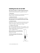
Installing the EiconCard S90 The steps below describe how to install the EiconCard S90. If you want the EiconCard S90 to be available to multiple users on a LAN, install it in the PC that will function as a gateway for the LAN. 1 Prepare the PC Turn off the PC and disconnect its power cable. Remove the cover of the PC according to the instructions that came with it. 2 Install the EiconCard S90 Insert the EiconCard S90 into any available PCI port.
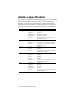
Selecting an Interface The EiconCard S90 can connect as a DTE to devices such as Data Service Units (DSUs) which support one of the following interfaces: V.24, V.35, EIA-530, V.36/RS-449, or X.21. It can also connect directly to a host computer, or back-to-back to another EiconCard. Table 1 lists the most common connections supported by the VHSI port, and specifies the part number of the required Eicon Technology cable. For information on making your own cables, see “Interface Specifications” on page 8.
Interface Specifications The standards compliant with each interface supported on the VHSI port are listed in Table 2. The rest of this section describes the allocation of pins used to implement the electrical and signaling requirements of each interface. A wiring diagram is also provided, to show the correspondence of the interface pinout to the VHSI port. Interface Standard Compatibility V.24 CCITT V.24 Signaling CCITT V.28 Electrical CCITT X.
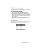
Cable Construction Information If you plan to construct your own VHSI cables, be sure to observe the guidelines given below. Wire Gauge, Grounding, and Pairing • Use 28 AWG 7-strand wire with 0.020–0.028" insulation. • The chassis must be grounded both by a drain wire and by the braid; both must be connected to the connector case and shell at each end of the cable. The braid must be connected through its full circumference. • Wires identified under the heading “Twisted Pairs” must be paired.
The V.24 Interface A pin-out diagram for the V.24 interface is shown in Figure 2. The signal definitions and names are listed in Table 4. PG N D TXD RXD RTS CTS DSR SG N D DCD 1 14 TCLK RCLK TEST DTR RLB RI DTECLK TI 25 13 Figure 2. V.
VHSI—V.24 Connections The wiring diagram below shows the connections required to construct a VHSI—V.24 cable. For the additional information required to construct your own cables, see “Cable Construction Information” on page 9. VHSI V.24 7 9 11 12 13 15 16 18 20 21 25 30 33 34 1 2 3 19 5 17 6 10 8 14 23 35 24 28 26 32 23 35 24 5 6 2 8 15 17 22 3 18 4 20 21 25 7 1 DRAIN WIRE BRAID Figure 3. VHSI—V.
The V.35 Interface A pin-out diagram for the V.35 interface is shown in Figure 4. The signal definitions and names are listed in Table 5. SGND CTS DCD RI TEST RLB R XD + R XD R C LK + R C LK - B TI NN A P G ND RTS DSR DTR T X D+ TX DCLK+ CLKT CLK+ TCLK- MM Figure 4. V.
VHSI—V.35 Connections The wiring diagram below shows the connections required to construct a VHSI—V.35 cable. For the additional information required to construct your own cables, see “Cable Construction Information” on page 9. TWISTED PAIRS (MANDATORY) VHSI V.35 Y AA R T V X P S U W D E F J L C H N NN B A 5 23 6 24 8 26 10 28 14 32 9 11 13 18 21 25 30 33 34 36 1 3 19 DRAIN WIRE BRAID Figure 5. VHSI—V.
The EIA-530 Interface A pin-out diagram for the EIA-530 interface is shown in Figure 6. The signal definitions and names are listed in Table 6. PG ND TXD+ RXD+ RTS+ CTS+ DSR+ SG N D DCD+ RTXCDCDCL KTRXCCTS- 1 13 14 25 TXDTRXC+ RXDRTXC+ TEST RTSDTR+ RLB DSRDTRCLK+ TI Figure 6.
VHSI—EIA-530 Connections The wiring diagram below shows the connections required to construct a VHSI—EIA-530 cable. For the additional information required to construct your own cables, see “Cable Construction Information” on page 9. TWISTED PAIRS (MANDATORY) VHSI EIA-530 4 22 5 23 6 24 7 25 8 26 9 27 11 29 12 30 13 31 17 35 21 33 34 1 2 19 2 14 15 12 3 16 4 19 17 9 5 13 6 22 20 23 8 10 24 11 18 21 25 7 1 DRAIN WIRE BRAID Figure 7.
The V.36/RS-449 Interface A pin-out diagram for the V.36/ RS-449 interfaces is shown in Figure 8. The signal definitions and names are listed in Table 7. 1 PG N D TXD+ TRXC+ RXD+ RTS+ RTXC+ CTS+ TEST DSR+ DTR+ DCD+ RLB RI CLK+ TI GND 20 TXDTRXCRXDRTSRTXCCTSDSRDTRDCD- C LK - 19 37 Fig. 8. V.
VHSI—V.36/RS-449 Connections The wiring diagram below shows the connections required to construct a VHSI—V.36/RS-449 cable. For the additional information required to construct your own cables, see “Cable Construction Information” on page 9. TWISTED PAIRS (MANDATORY) VHSI V.36 / RS-449 4 22 5 23 6 24 7 25 8 26 9 27 11 29 12 30 13 31 17 35 18 21 33 34 1 2 19 4 22 5 23 6 24 7 25 8 26 9 27 11 29 12 30 13 31 17 35 15 10 14 18 19 20 37 DRAIN WIRE BRAID Figure 9. VHSI—V.
The X.21 Interface 1 A pin-out diagram for the X.21 interface is shown in Figure 10. The signal definitions and names are listed in Table 8. PG N D T(A) C(A) R(A) I(A) S(A) B(A) SGND 9 T(B) C(B) R(B) I(B) S(B) B(B) PG ND 8 15 Figure 10. X.
VHSI—X.21 Connections The wiring diagram below shows the connections required to construct a VHSI—X.21 cable. For the additional information required to construct your own cables, see “Cable Construction Information” on page 9. TWISTED PAIRS (MANDATORY) VHSI X.21 1 19 4 22 5 23 6 24 8 26 11 29 12 30 8 2 9 7 14 4 11 6 13 5 12 3 10 1 DRAIN WIRE BRAID Figure 11. VHSI—X.
Back-to-Back Connections The wiring diagram below shows the connections required to construct a back-to-back VHSI—VHSI cable. Back-to-back operations are conducted through the V.36 interface. For the additional information required to construct your own cables, see “Cable Construction Information” on page 9. TWISTED PAIRS (MANDATORY) VHSI VHSI 6 24 4 22 4 22 6 24 5 8 26 23 7 9 27 25 11 29 12 30 17 35 13 31 12 30 11 29 7 9 27 25 5 8 26 23 13 31 17 35 1 2 19 1 2 19 DRAIN WIRE BRAID Figure 12.
Technical Specifications Technical Data • • • • PCI bus compatible (32-bit slot) Motorola 68302 CPU @ 25 MHz 1 MB RAM 1 MB FLASH memory Hardware Installation • Automatic configuration of interrupt request level setting and I/O address • 32-bit I/O access External Interface • One 36-pin female port VHSI Port • • • • One VHSI port connects to 36-pin high-density male connector Support for V.24, V.35, EIA-530, and V.36/RS-449 X.21 with V.11 (X.
International Regulatory Information Regulatory Information for the USA: FCC Warning Declaration of Conformity We: Eicon Technology Inc. 2155 Chenault Drive Suite 503 Carrollton, Texas USA 75006 1-800-80-EICON (972) 417-5515 Fax: (972) 417-5610 Declare under our sole legal responsibility that the product to which this declaration relates, are in conformity with Part 15 of the FCC Rules.
Regulatory Information for Canada This digital apparatus does not exceed the Class B limits for radio noise emissions from digital apparatus set out in the Radio Interference Regulations of the Canadian Department of Communications. Le présent appareil numérique n’émet pas de bruits radioélectriques dépassant les limites applicables aux appareils numériques de la classe B prescrites dans le Règlement sur le brouillage radioélectrique édicté par le ministère des Communications du Canada.
Table 9. Creepage Distances The creepage distances apply when installed in a normal office environment. The creepage distances shown in parentheses apply where the local environment within the PC is subject to conductive pollution or dry non-conductive pollution which could become conductive due to condensation. These distances can be checked by measuring between the adjacent parts as shown below. X shows the clearance distance which is the shortest distance in air between two points.
Limited Warranty Eicon Technology Corporation warrants to the original purchaser of this Eicon Technology Product that it is to be in good working order for a period of five (5) years from the date of purchase from Eicon Technology or an authorized Eicon Technology dealer.
Product Comment Form EiconCard S90 Installation Guide 203-187-01 We value your comments. Please use the tables below to rate this product.
Printed in Canada