Diva Server for Windows NT Reference Guide www.eicon.
Seventeenth Edition (February 2003) 206-288-17 Diva ISDN is a registered trademark of Eicon Networks Corporation. Microsoft, Windows, and Windows NT are registered trademarks of Microsoft Corporation. Security Dynamics, ACE/Server and SecurID are registered trademarks and PASSCODE and PINPAD are trademarks of Security Dynamics Technologies Inc. All other brand and product names are trademarks or registered trademarks of their respective owners.
Contents About This Online Guide .............................................................................. 5 How to use this online guide ................................................................................... 5 Structure of this guide ............................................................................................. 5 General information on this guide ........................................................................... 6 About Diva Server for Windows NT .................
Via the WAN Miniport ............................................................................................ 78 Changing Your Installation ......................................................................... 82 Adding Diva Server adapters ................................................................................ 82 Changing the configuration ................................................................................... 83 Updating the software settings .................................
CHAPTER 1 About This Online Guide How to use this online guide • To view a section, click the corresponding bookmark located on the left. • To view a topic that contains further information, click the corresponding blue underlined phrase. • You may wish to print out the pages required for installing the drivers. Structure of this guide This guide provides a detailed description of how to install and configure Diva Server for Windows NT, and how to troubleshoot your ISDN connection.
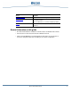
Section Contents Management Tools Tools available for monitoring and managing connections. Troubleshooting Debugging tools available for locating installation errors or connection problems. Tips and explanations on common installation problems. Features Overview of the functions provided by the various interfaces. General information on this guide • This manual describes the installation of the Diva Server for Windows NT software. • All screen shots in this manual are based on Windows NT 4.0.
CHAPTER 2 About Diva Server for Windows NT Diva Server for Windows NT enables you to use your Eicon Diva Server adapter with Windows NT 4.0. Diva Server for Windows NT provides modem emulation, connectivity via the Windows NT Remote Access Service (RAS) over ISDN, a CAPI interface for ISDN-based applications, and a TAPI interface for telephony-based applications. Features General features The list below provides an overview of the features supported by Diva Server for Windows NT.
• Channel-bundling using the Multilink PPP standard • Modem connections up to 56 kbps (V.90) • COM Port (modem emulation) • Support for CAPI-based applications through CAPI 2.
Diva Server TSP features • Supplementary services based on CAPI: CLIP, CLIR, COLP, COLR, HOLD, CFU, CFB, CFNR, ECT, AoC • Media mode (unknown, interactive voice, automated voice) • Wave audio format (8 bit 8 kHZ a-law, 8 bit 8 kHz µ-law, 8 bit 8 kHz PCM) • DTMF tone generation and detection (based on CAPI) Q-Sig features Diva Server for Windows NT supports the following Q-Sig features: • Basic call • Redirected number • Connected name • AoC (Advice of Charge) • Message waiting Channelized T1 (RBS) feature
• Diva Server Voice BRI-2M 2.0 PCI • Diva Server 4BRI-8M PCI • Diva Server Voice 4BRI-8M PCI • Diva Server 4BRI-8M 2.0 PCI • Diva Server Voice 4BRI-8M 2.0 PCI ISDN PRI adapters • Diva Server PRI PCI: Diva Server PRI PCI, Diva Server PRI-9M PCI, Diva Server PRI-23M PCI, Diva Server PRI-30M PCI • Diva Server PRI 2.0 PCI: Diva Server PRI-0M PCI, Diva Server PRI-4M PCI, Diva Server PRI-8M PCI, Diva Server PRI-30M 2.
Note on downloaded software If updates of the Diva Server for Windows NT software are later downloaded from the Eicon web site, please note the following: • Extract the files to your hard disk drive. Do not change the directory structure of the extracted files. • This manual assumes that the installation files have been copied into the directory C:\ISDN. If necessary, change the drive letter or path according to your system configuration.
Overview of the software Driver structure The Diva Server for Windows NT software provides a unified software structure for all Diva Server adapters and supports a large number of network applications. See the software structure in the illustration below. The fields highlighted in gray specify the part of the software that must be installed to enable the use of the Windows NT Remote Access Service (RAS) over ISDN or channelized T1.
WAN-Miniport driver The Eicon WAN-Miniport driver allows Diva Server for Windows NT to use the Windows NT Remote Access Service (RAS) over ISDN. In this case, it acts as an NDIS 4.0 WAN-Miniport driver. See WAN-Miniport driver on page 25. CAPI CAPI 2.0 (Common ISDN Application Interface version 2.0) is a standardized interface for ISDN applications. Diva Server for Windows NT provides the CAPI 2.0 interface for 16-bit and 32-bit CAPI-based applications. See CAPI 2.0 on page 56.
Installation sequence See the illustration below for a schematic view of the installation sequence of Diva Server for Windows NT: Required Information Installation Procedure Preparation ISDN adapter type Install the Diva Server adapter Required Documentation Chapter: About Diva Server for Windows NT Requirements for software installation Chapter: Installation and Configuration Preparing for the installation of the basic drivers Printed guide that came with your Diva Server adapter ISDN D-channel protoc
CHAPTER 3 Installation and Configuration Basic drivers Preparing for the installation of the basic drivers Before installing the software, check the following items: • What type of Diva Server adapter is installed? • For the Diva Server BRI-2M ISA adapter: Is resource allocation by your computer’s BIOS enabled? Enabling resource allocation ensures that the computer’s BIOS allocates hardware resources.
Installing the network protocols Depending on the purpose of the ISDN connection, different network protocols are required. Install the network protocols that you want to support (NetBEUI, TCP/IP, or IPX). Before installing Diva Server for Windows NT, check that the required protocols are installed on the system: 1. Select ‘Start > Settings > Control Panel’. Double-click ‘Network’. 2. Select the ‘Protocol’ tab.
3. In the ‘Select OEM Option’ dialog box, select the Diva Server adapter installed in the computer. • ‘Eicon detect and install all adapters’: The Diva Server for Windows NT software will be installed for all Diva Server adapters installed in the computer. • ‘Eicon Diva Server ...’: The Diva Server for Windows NT software will be installed for the selected adapter.
Configuration profiles Multiple configurations may be saved if several different parameters for several configurations are needed. There are 10 memory locations per Diva Server adapter available for configuration profiles. The memory locations are labeled ‘Untitled Profile 1’ to ‘Untitled Profile 10’ by default. The names may be changed in the editing field as required. The configuration may be changed with the ‘+’ and ‘–’ keys or by clicking the corresponding icons.
4. If you have selected the ‘RBS T1’ switch type: • Select the trunk type that corresponds to the trunk type of your switch: • Wink Start • Loop Start • Ground Start Default setting is ‘Wink Start’. All trunk types are defined in the TIA/EIA-464B specification; the ‘Wink Start’ trunk type is also defined in AT&T TR4158. • Select the dial type that corresponds to the dial type of your switch. • Pulse • DTMF (Dual-Tone Multifrequency Signaling) • MF (Multifrequency Signaling) Default setting is ‘DTMF’.
You must also specify the ISDN Interface Type for each individual controller. To do so, select ‘[] Basic Settings’ for each of them and select the required ‘ISDN Interface Type’. SPID Settings If you are in North America and use a BRI interface, select the option ‘SPID Settings’ from the ‘Page’ box. Note: With a Diva Server 4BRI or Voice 4BRI adapter, SPIDs must be specified individually for each of the four controllers (controller [1] to controller [4]).
3. If you have selected ‘One SPID’ or ‘Two SPIDs’, enter the SPID numbers specified by your ISDN service provider in ‘SPID’. Hardware Settings If you are using a Diva Server BRI-2M ISA-bus adapter and you need to configure specific hardware resources, select ‘Hardware Settings’ from the ‘Page’ box. Disable ‘Automatic Configuration’ and enter the required I/O port base address and interrupt number.
• Specify if the adapter should generate internal ring tones when they are not provided by the switch or PBX. • Specify if your adapter is operated in a hunt group or used as monitoring device. For detailed explanations of the ‘Advanced Settings’, see the online help (‘Help’ or ‘F1’). ISDN Protocol Settings The ‘ISDN Protocol Settings’ tab contains parameters for configuring the protocol software. Specific information on the ISDN, Q-Sig, or RBS T1 protocol is requested here.
ISDN Line Settings The ‘ISDN Line Settings’ tab contains different parameters depending on whether you use a Diva Server basic rate adapter or a Diva Server primary rate adapter. See ISDN line settings for BRI interfaces or ISDN line settings for PRI or T1 interfaces below. ISDN line settings for BRI interfaces If you are using a North American switch type and a BRI interface, use the ‘ISDN Line Settings’ tab to activate supplementary services for your line.
Enable the ‘Fractional T1/E1 Line’ option. Indicate the number of B-channels that your line offers in ‘Number of B-Channels’. Also, indicate the lowest B-channel that is assigned to your line in ‘Lowest B-Channel’. For detailed explanations of the ‘ISDN Line Settings’, see the online help (‘Help’ or ‘F1’). Completing the basic installation After you confirm the configured parameters, additional files are copied.
WAN-Miniport driver To install the WAN-Miniport driver, you must have a fully installed Eicon Diva Server adapter. If the WAN-Miniport driver has already been installed, see Configuring the WAN-Miniport driver on page 26 for more information. The WAN Miniport is required if you want to use Windows NT Remote Access Service. See Remote Access Service (RAS) on page 37. Installing the WAN-Miniport driver Note: You must be logged on as ‘administrator’ to install Diva Server for Windows NT.
Configuring the WAN-Miniport driver Remote Access Service handles communications through ports. The WAN-Miniport driver assigns one ISDN B-channel or channelized T1 channel to each port. These ports can be configured using the ‘Eicon WAN-Miniport Driver Setup’ dialog box. Port List In the ‘Port List’, you configure the ISDN or channelized T1 ports that are to be made available to the RAS for communications. The ports are assigned automatically to the first installed adapter.
3. In the ‘Change Port’ dialog box, select the adapter that is to be assigned to the port. Click ‘OK’. 4. You can also leave a port unassigned so that the port number is reserved for subsequent configurations (see the illustration below). Click ‘OK’. The configured port is displayed in the ‘Eicon WAN-Miniport Driver Setup’. Note: If new ports are added or deleted, the changes will become effective only when the system is restarted. 5.
The following options appear under ‘Page’ in addition to the ‘Port List’: • Advanced Settings: Accept analog calls, B-channel protocol, no answer timeout (see Advanced Settings on page 30) • Shorthold Settings: To configure the shorthold timer (see Shorthold Settings on page 31) • Authentication Features: Access security with RAS authentication or with Security Dynamics, if an ACE/Server is available (see Authentication Features on page 32) • Number Checking: Access security by call number checking (see Num
When using the German ISDN protocol 1TR6, the terminal device selection digit (EAZ) is used to distinguish the ports. The EAZ consists of only one digit. This enables up to 9 ports to be distinguished. Note: EAZ = 0 is a global call so every call is accepted by any port. Therefore, EAZ = 0 should be used only if no other similar devices are on the same ISDN line. To specify the called port, the caller needs to attach the EAZ to the normal telephone number.
4. Enter the corresponding MSN or EAZ in ‘Phone number’. 5. If required, enter the corresponding subaddress in ‘SUB’. 6. Click ‘OK’. Advanced Settings Select the ‘Advanced Settings’ page if the following parameters need to be configured: Accept Analog Calls Leave this option enabled if analog calls are also to be accepted. Note: If there are other devices on the same bus, such as a telephone or fax, and the WAN Miniport has not been assigned a special MSN, this option may cause problems.
• PIAFS (China, speed detection): The transfer rate used by your PIAFS B-channel protocol is automatically detected. Select this option only if your incoming PIAFS calls use variable transfer rates because speed detection might slow call establishment down. Note: The ‘B-Channel Protocol (incoming)’ parameter applies only to incoming calls. If you want to use PIAFS for outgoing calls, you have to indicate it as an extension to the number to be dialed. See page 67 for further information.
Shorthold Time The ‘Shorthold Time’ option allows you to specify after how long the ISDN connection is broken if no data is transmitted. Shorthold time = 0 means that the computer will not break a connection itself but will accept shorthold requests from the remote side. Callback Prefix The ‘Callback Prefix’ is used to insert one or more numbers in front of the callback numbers for all clients.
Server Security Level • The ‘Security Dynamics relaxed’ setting causes the Eicon WAN-Miniport driver to attempt to have the ACE/Server authenticate incoming calls. However, if it is not successful, it will also accept the call with the RAS authentication only. • The setting ‘Security Dynamics strict’ causes the Eicon WAN-Miniport driver to place only calls to the RAS that have first been accepted by the ACE/Server.
Number Checking File If ‘Number Checking’ is activated, enter the path of the configuration file which contains the call numbers authorized by the RAS, e.g. ‘Data_Files\Eicon\Number_Checking.cfg’. Note: The configuration file for Number Checking is read only when the driver is started. Therefore, changes to the file take effect only after restarting the computer.
• If a semicolon [;] is placed at the beginning of a line, all subsequent characters until the end of the line will be ignored. This can be used to place comments next to call numbers. • A maximum of 1000 entries may be included, corresponding to 1000 configured call numbers. Callback Settings Select the ‘Callback Settings’ page if you wish to configure special callback settings. Ignore Callback Number Note: This option is only relevant if you use your server also in client mode.
Completing the installation of the WAN-Miniport driver After accepting the configured parameters, the installation of the Eicon WAN-Miniport driver for RAS is complete. Follow the directions on the screen and read the corresponding section in this guide: • To continue with the RAS installation or configuration, click ‘Yes’ to confirm. See Remote Access Service (RAS) on page 37. • If you wish to install the Eicon Port driver, click ‘Yes’ to confirm. See Eicon Port driver on page 41.
Remote Access Service (RAS) Note: Before continuing, you should read the documentation on Remote Access Service that came with your copy of Windows NT. Installing RAS If Windows NT Remote Access Service is not yet installed on the computer, install it now. The Diva Server for Windows NT installer prompts you automatically to install RAS if you chose to install the WAN-Miniport driver. In this case, RAS Setup appears during installation.
When installing Diva Server for Windows NT for the first time, the new ports must be added first. 1. Click ‘Add’. 2. Select ‘ISDN1-DIWAN’, and click ‘OK’. 3. Repeat this procedure for each additional B-channel to be set up as a port in the RAS Setup. The ‘Remove’ function may be used to delete a port. The ‘Clone’ function sets up the next new port with the same parameters as the selected port. Port configuration Select a port to configure and click ‘Configure’.
Network configuration Click the ‘Network’ button in the ‘Remote Access Setup’ dialog box to specify the network protocols that RAS should support. It is not possible to specify different protocols for individual ports. Dial-out Protocols Under ‘Dial-out Protocols’, select the protocols that you wish to make available for outgoing ISDN connections: • If connections to a Windows NT RAS server are required, select the protocol that is configured on the remote RAS server.
Enable Multilink (Windows NT Server only) The ‘Enable Multilink’ option activates channel bundling according to the Multilink PPP standard. This means that two or more (max. 6) B-channels or channelized T1 channels can be bundled for a single higher-speed connection. Note: Additional information on setting up the network protocols can be found in the RAS online help or the Windows NT RAS documentation.
Eicon Port driver Diva Server for Windows NT provides the Eicon Port driver, i.e. virtual COM port, for modem emulation. It behaves in the Windows NT system like a serial interface with a connected modem. The virtual COM port allows you to install virtual TAPI modems for a variety of connections: fax, V.110, V.120, HDLC, X.75, or analog modem. Thus, with Diva Server for Windows NT you can send and receive faxes, access ISDN mailboxes or communicate with analog modems.
3. In the ‘Select OEM Option’ dialog box, select ‘Eicon Port Driver’. Click ‘OK’. After some files are copied to your hard disk, the ‘Eicon Port Driver Setup’ dialog box appears. See Configuring the Eicon Port driver below. Configuring the Eicon Port driver The Port driver is configured in the ‘Eicon Port Driver Setup’ dialog box. By default, one port is installed for each B-channel during the installation of the Port driver.
If multiple Diva Server adapters are installed, assign each adapter to every communications port to which it needs access. Each port will use one B-channel on the assigned adapter. This means for example that one Diva Server BRI-2M adapter can be used by two ports and one Diva Server 4BRI-8M adapter can be used by eight ports. When installing the Port driver, the ports are set up automatically according to the type and number of currently installed adapters.
5. Click ‘OK’. The configured port is displayed in the ‘Eicon Port Driver Setup’. Note: If new ports are added or deleted, the changes will become effective only when the system is restarted. 6. If you do not plan to use the Eicon virtual COM Port driver with advanced configuration, click ‘OK’ to terminate the Port driver configuration.
MSN When using Euro-ISDN (E-DSS1) or any other national ISDN protocol that enables Multiple Subscriber Numbering (MSN), different MSNs (up to 23 digits in length) may be used to distinguish the ports. Enter the corresponding value as ‘Phone number/extension’ parameter. In general, the MSNs are assigned by the telco company and are used in the terminal description. When using the German ISDN protocol 1TR6, the terminal device selection digit (EAZ) is used to distinguish the ports.
Generic Server Modem To configure the Generic Server Modem, check the ‘Advanced Parameters’ check box and select ‘Generic Server Modem’. Support calls with synchronous PPP Check the option ‘Support calls with synchronous PPP’ if the virtual COM Port driver should accept incoming calls with synchronous PPP (ISDN-specific framing method used by ISDN networking products). By default, the virtual COM Port driver can only be used for incoming calls from asynchronous devices.
Completing the Eicon Port driver installation After accepting the configured parameters, the installation of the Eicon virtual COM Port driver is complete. Follow the directions on the screen and read the corresponding section in this manual: • If you wish to install the Eicon driver for CAPI 2.0, click ‘Yes’ to confirm when prompted. See CAPI 2.0 on page 56.
Command Description AT E [] Echo Mode - In echo mode, all commands sent to the modem are echoed back to the terminal. n > 0: Echo Mode ON n = 0: Echo Mode OFF AT H [] Hangup - Disconnects the line. 0 < n < 3 is accepted for compatibility, but ignored by the driver. AT I [] Info - Returns the modem identification string. +++ Escape - This escape sequence switches the modem back from the data mode to the command mode.
Command AT &F [] Description Factory Setting - Resets the modem and restores the predefined modem configuration profile . n=1 X.75 (L1:HDLC framing, L2:X.75 SLIP, L3:transparent) +iM1 +iP1 +iS7/0 +iN255 +iB255 +iC1 E1 Q0 V1 X4 &D2 &K0 &Q0 \V0 \N3 %C3 -J1 +iU0 +iD0 +iF0 S0=0 S7=60 S9=6 S10=14 n=2 V.110 syncron (L1:V.110 syncron, L2:transparent, L3:transparent) +iM1 +iP2 +iS7/0 +iN255 +iB255 +iC1 E1 Q0 V1 X4 &D2 &K0 &Q0 \V0 \N3 %C3 -J1 +iU0 +iD0 +iF0 S0=0 S7=60 S9=6 S10=14 n=3 V.110 asyncron (L1:V.
Command Description AT &V [] Displays the current configuration of the modem driver and the last number that has been dialed. n != 0: Also lists all predefined profiles. AT \T [] Inactivity Timeout - The modem driver releases the connection if there was no data traffic for n times 10 seconds. n = 0: Disables inactivity timeout. n > 0: Disconnects after n * 10 seconds idle time. AT \D [] Debug Level - Specifies the kind of events that should be reported by the driver.
Command Description AT +MS=[] [,[] [,[] [,[] [,[] [,[]]]]]] Modulation Selection Set Modulation mod = B103:1) mod = B212A: mod = V21: mod = V22: mod = V22B: mod = V23C:1) mod = V32: mod = V32B: mod = V34:1)2)3) mod = V90: mod = V90A:1 Data Rate Range 300 bps 1200 bps 300 bps 1200 bps 1200 - 2400 bps Tx:75 bps/Rx:1200 bps Outgoing call Tx:1200 bps/Rx:75 bps Incoming call 4800 - 9600 bps 4800 - 14400 bps 2400 - 33600 bps 28000 - 56000 bps send (server -> client) 2400 -
Command AT \V Description Indication of connection parameters in CONNECT response. n=0 n=1 Connection parameters are not indicated. Connection parameters are indicated. The connection parameters are displayed in the following format: CONNECT //:TX/:RX> modulation: options: txspeed: rxspeed: AT #CID= V21, V22, V23, V32, V34, V90 etc. (see AT +MS command) LAPM/V42BIS, LAPM, MNP5, MNP 300, 1200, 2400, ..., 33600 etc. (transmit rate) 300, 1200, 2400, ...
Command Description AT +FMDL? Returns the name of the modem model. AT +FREV? Returns the product version. ISDN-specific AT commands Command AT +iM Description Working Mode - Sets the working mode of the modem. n = 0: n = 1: n = 2: n = 3: n = 4: n = 5: n = 6: AT +iP Undefined Data Modem Fax Modem Voice Modem RNA Modem (Enables frame conversion for RNA networking.) BTX Modem (Enables frame conversion for modem based BTX decoders.) Frame Mode - Keeps frame boundaries of the ISDN data frames.
Command Description AT +iS / Service Indicator/Additional Service Indicator It tells the remote site which kind of connection you want to establish. Command affects the Low-Layer Capabilities (LLC) element on the SETUP message.
Command Description AT +iF RNA-Framing (applies only to the RNA mode) n = 0: No Framing check n = 1: Force synchronous conversation n = 2: Force asynchronous conversation n = 3: Detect necessary conversation by analyzing incoming data packets.
CAPI 2.0 Diva Server for Windows NT provides the CAPI 2.0 interface for CAPI-based applications. If CAPI 2.0 has already been installed, see Installing and configuring CAPI 2.0, step 4 (on page 57). About CAPI installation and configuration • The CAPI 2.0 driver makes the supported Diva Server adapters available for CAPI 2.0 applications. • Applications that use CAPI 2.0 can use the CAPI 2.0 drivers to access various controllers, numbered from 1 to n.
3. In the ‘Select OEM Option’ dialog box, select ‘Eicon CAPI 2.0 Driver’. Click ‘OK’. CAPI 2.0 will then be installed. 4. CAPI can now be configured in the ‘Eicon CAPI 2.0 Driver Setup’ dialog box. An installed Eicon Diva Server adapter may be assigned to every CAPI controller in the ‘Eicon CAPI 2.0 Driver Setup’ dialog box on the ‘Controllers’ page. Additional CAPI controllers may be added, changed or deleted as desired.
If you select the ‘Advanced’ option in the ‘Eicon CAPI 2.0 Driver Setup’ dialog box under ‘Page’, you can configure additional settings. For further information, see the online help. CAPI sharing for the Windows NT Network Your Diva Server CD-ROM offers the channel sharing software solution by EES. EES Channel Sharing enables you to use the Windows NT Server CAPI interface in the network. The provided EES Channel Sharing software is an evaluation version.
CHAPTER 4 Installing Additional Components Installing virtual modems If you want to use Diva Server for Windows NT to send faxes, access ISDN mailboxes or communicate with analog modems, you first have to install and configure the Eicon Port driver (which you might have done during the installation process, see Eicon Port driver on page 41). When the Eicon Port driver is installed, you have to install the virtual modems which are to use the Port driver.
• Eicon Diva Fax Modem: Install this modem for sending and receiving faxes of fax group III. • Eicon Diva Generic Server Modem: This modem is designed for incoming calls only. It supports automatic B-channel call distribution which means that it can distinguish incoming calls according to service and protocol and distribute each call to the corresponding application (e.g. fax or data). Nevertheless, callback is possible with the Eicon Diva Generic Server Modem. It should be used for a dial-in server, e.g.
9. Click ‘Finish’ and afterwards ‘Close’. • If you want to use the configured modem with RAS, click ‘Yes’ in the corresponding dialog box. Go on to step 10. • If you do not want to use the configured modem with RAS but only with applications such as HyperTerminal, click ‘No’. You can select the modem in your application. 10. In the ‘Remote Access Setup’ add the port which you have selected before (see RAS setup on page 37). Before you can use the modem, you have to restart your computer.
4. In the ‘Diva Server TSP Configuration’ dialog box, click the ‘Adapter and Properties’ tab. 5. Select and enable the adapter in the list for which you want to configure TSP properties. 6. Select the maximum number of lines that you want to use for Diva Server TSP. 7. Indicate whether multiple subscriber numbers or a range of extensions are assigned to your ISDN or channelized T1 line.
8. Click the ‘Common’ tab in the ‘Diva Server TSP Configuration’ dialog box. 9. Enter the prefixes that should be added to the calling party number and connected number for your TAPI application. • If you are working behind a PBX, enter the prefix that is required for an external line, e.g. ‘9’. • Enter the area code prefix that should be added to the area code for all national calls if necessary, e.g. ‘0’.
11. Click ‘OK’. The installation of the Diva Server TSP is completed and the wave driver for the Diva Server TSP is installed. 12. In the displayed message box (which informs you that the wave driver has been installed), click ‘OK’. 13. Restart your computer to make the wave driver available for your system. To check if the wave driver has been installed successfully, click ‘Start > Settings > Control Panel’. Double-click the ‘Multimedia’ icon. Click the ‘Devices’ tab.
CHAPTER 5 Using Dial-Up Networking or RAS Administration In the terminology used by the Remote Access Service, the calling station is referred to as the Client and the called station as the Server. The RAS client/server architecture allows a station to be defined simultaneously as a server and as a client and therefore enables simultaneous initiation of outgoing and incoming ISDN. For example, this enables the peer-to-peer connection of two Windows NT workstations.
3. The name of the telephone book entry that is to be dialed may be entered in the ‘New Telephone Book Entries Wizard’ dialog box. Note: If you click ‘No Additional Information Required’, the ‘Edit Telephone Book Entry’ dialog box appears. All settings can be made here, but no explanations are available. The dialog box for setting up the RAS client explained below is no longer visible. 4. Click ‘Next’. 5. If only RAS is required, click ‘Next’ in the ‘Server’ dialog box.
8. Enter the phone number of the server required in the ‘Phone Number’ dialog box. If the server is configured to use subaddresses, you must specify the appropriate subaddresses in the ‘Phone Number’ dialog box, separated by the vertical stroke ‘|’, (the pipe symbol or [Alt] and the digits [0], [1], [2] and [4] on the numeric keypad). For example, if the phone number is 07152932940 SUB 41, you must enter 07152932940|41.
Designation Description Services ^XP synchronous HDLC transparent (standard) ^V.120 synchronous, also requires the transfer rate to be entered ^V.110 asynchronous, also requires the transfer rate to be entered ^GSM1 V.110/9600/intermediate rate 16 kbps, async. without flow control ^GSM2 V.110/9600/intermediate rate 16 kbps, async. with flow control ^GSM3 V.110/9600/intermediate rate 16 kbps, async. with flow control, without LLC ^PIAFS PIAFS 2.1/64K (Diva Server BRI-2M 2.0, Voice BRI-2M 2.
To observe the progress of a connection, click ‘Next’ and then click ‘Monitor Status’ in ‘Dial-Up Networking’ (see also Dial-Up Networking monitor on page 70). By clicking ‘Next’, then ‘Edit Entry and Modem Properties’ and selecting the server adapter, the desired network protocol(s) can be set for every telephone entry. More detailed information can be found in the Windows NT RAS documentation.
• Set by Caller The client establishes the connection to the server, sends its current call number and then breaks the connection. The server calls the client back at the number given and therefore assumes the charges for the call. The client’s call can therefore be made from any site. • Preset To The client establishes the connection to the server, thereby indicating that a connection is required, and then breaks the connection. The server calls the client back at the preassigned call number.
Click the ‘Preferences’ tab. In this tab, you can change settings such as ‘Display as icon beside the clock in the taskbar’ or ‘Display as a window on the desktop’. The following window then appears on the desktop: If the fields are in color, this indicates an activity.
CHAPTER 6 Using Shorthold Mode During data exchange between computers, there are always idle periods. If the connection continues during these periods, unnecessary charges will be incurred. The shorthold mode reduces these charges. It breaks the physical connection during periods where no transmission takes place and only reconnects to the remote station when data needs to be transmitted.
However, if the other side wishes to be the first to send a data packet, it will have to ‘notify’ the side that initiated the shorthold. This means that it calls without establishing a connection. The side controlling the shorthold will then call back and establish the connection.
… Charged to the RAS server The RAS client calls the RAS server and requests a callback. The RAS server establishes the connection using the callback function of RAS, initiates the shorthold and reconnects the subsequent calls. For example, in the case of remote workstations, users can call the company server and have the RAS server call back. This ensures that the server bears all charges for the call.
Callback numbers Regardless of whether the RAS client or the RAS server carries the charges, the server requires the client’s correct callback number. Note: If the exchange does not send the client’s call number, the WAN-Miniport driver will reject the RAS server’s shorthold requests. In this case, it will have no information on what number it should dial for a callback.
CHAPTER 7 Using Security Dynamics Authentication Diva Server for Windows NT supports Security Dynamics authentication as an additional security feature against unauthorized access to your Windows NT server. If there is a Security Dynamics ACE/Server (ACE = Access Control & Encryption) on the network and all authorized clients have the corresponding SecurID tokens, access to the Windows NT server via ISDN can also be made secure with Security Dynamics authentication.
The server side The Security Dynamics ACE/Server can be installed on the Windows NT Server directly. It is not necessary to add additional protocols like RADIUS or TACACS+. The ACE/Agent from Security Dynamics should also be installed on the server. The ACE/Agent controls the Dial-Up Networking connection.
4. In ‘After dialing (login)’, check the option ‘Pop up a terminal window’. Click ‘OK’. 5. After dialing into the server, the ‘After Dial Terminal’ window pops up. This terminal window is used for the Security Dynamics authentication and for some additional conversation to the server, such as ‘Next Tokencode’ and ‘Next PIN’ mode. Enter your username, domain and passcode. To continue, click ‘Done’.
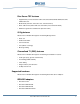
See in the illustration below how the Security Dynamics authentication functions: SecurID Token Windows NT Server with Diva Server for Windows NT Windows 95 Client 582976 SECUR ID Query over TACACS+ Protocol ISDN 582976 SECUR ID SecurID Token Windows NT Client ACE/Server The server side The authentication query by the WAN-Miniport driver uses the following principle: Example: With the WAN-Miniport driver, a client logs on with the following entries: User: sales;fred;4893776253 Password: cat Domai
• Edit the password in ‘sdtacplus.cfg’, which is used for the TACACS+ encryption between ‘_sdtacplusd’ and Diva Server for Windows NT (valid for ACE/Server, version 2.2, on a HP-X computer, version 10.01, with Security Dynamics D200 SecurID tokens). In Diva Server for Windows NT this password can be edited in NCPA/ ‘Eicon authentication Service’/Config. The password must of course be identical on both sides.
Eicon Authentication Service If the Security Dynamics authentication has been configured in the WAN-Miniport driver, the Eicon Authentication Service still has to be installed. You will be prompted when the network configuration is complete. Click ‘Yes’ in the appropriate dialog box to confirm. Finally, the ‘Eicon Authentication Service Setup’ dialog box will appear: Enter the IP address of the ACE/Server and the required password.
CHAPTER 8 Changing Your Installation Adding Diva Server adapters If additional Diva Server adapters are added, the WAN-Miniport and the Eicon Port driver configuration must be updated after installation. Adding driver software 1. Click ‘Start > Settings > Control Panel’. Double-click ‘Network’. 2. Click the ‘Adapter’ tab. 3. Click ‘Add’ and follow the instructions on the screen (see also Installing the basic drivers on page 16). Update WAN-Miniport configuration 1. Click the ‘Adapter’ tab. 2.
6. Add the newly installed adapter and set up the ports (see also Configuring the Eicon Port driver on page 42). 7. Click ‘OK’. Changing the configuration Reconfiguring the Diva Server adapter, the WAN-Miniport driver, the Port driver, or the CAPI 2.0 Reconfigure the settings for the adapter, the WAN-Miniport driver, the Port driver, or CAPI 2.0 as follows: 1. Click ‘Start > Settings > Control Panel’. Double-click ‘Network’. 2.
Updating the software settings For updates to the Eicon software, or to install additional network protocols, follow the steps below: 1. Click ‘Start > Settings > Control Panel’. Double-click ‘Network’. 2. Click the ‘Adapter’ tab. 3. If you want to install an additional network protocol, select the Diva Server adapter on which the protocol is to be executed. Click ‘Update’. 4. Enter the path to the update files, i.e.
4. In the displayed message box, click ‘OK’ to confirm the new network settings. 5. Restart the computer. Note: The Remove script does not uninstall the Diva Server Telephony Service Provider. To uninstall the Diva Server TSP, click ‘Start > Settings > Control Panel’. Double-click the ’Telephony’ icon. Click the ‘Telephony Drivers’ tab. Select the ‘Diva Server Telephony Service Provider’ and click ‘Remove’.
CHAPTER 9 Installation in Unattended Mode This chapter describes how to install the Diva Server for Windows NT software in unattended mode. The unattended installation requires no user input; the required parameters are read from a plain text file. Note: As the unattended installation requires specific knowledge about the installation process it should be done by the administrator.
Options file In unattended mode, the instructions and parameters for the installation are read from a plain text file known as the options file. The format of the options file is based on the standard Windows INI format. [SECTION NAME] PARAMETER1=VALUE1 For each component a section in the options file is checked. As the Diva Server for Windows NT software consists of several components (see Driver structure on page 12), several sections are required in the options file.
• Common components section (see Common components section on page 101): The components that are common for all Diva Server adapters are the WAN Miniport, the Eicon Port driver and the CAPI interface driver. You can configure the WAN Miniport and the Eicon Port driver. The section names for the WAN Miniport and the Port driver are ‘WAN’ and ‘MODEMS’. General section The general section defines which optional components will be installed.
Adapter Section name Diva Server PRI 2.0 versions (0M, 4M, 8M, 30M 2.0), DSPRI_2 Diva Server T1/PRI versions (T1/PRI, T1/PRI-4M, T1/PRI-8M, T1/PRI-24M) Diva Server Voice PRI versions (4M, 8M, 24M), Diva DSPRI_2_VOICE Server Voice T1/PRI versions (4M, 8M, 24M) Depending on the type of Diva Server adapter and the selected options, some parameters are optional.
• 1 (on): The Diva Server adapter is switched to high-impedance state and layer 1 is not activated until an application signals that it is ready to service calls. Note: If your Diva Server adapter is operated in a hunt group, the ‘EnableLayer1Tristate’ parameter must be used in combination with the ‘AutomaticLayer1Down’ parameter in the [CAPI] section, see AutomaticLayer1Down on page 106. InterruptNumber The interrupt number must be set according to the hardware configuration of the adapter.
Protocol Defines the ISDN D-channel protocol by a keyword. Use the table below to find the keyword that specifies your country’s protocol.
ForceLaw ForceLaw specifies which voice coding is used. Voice coding defines how voice data are transmitted over the ISDN. Possible settings are: • 0 (Protocol Default): Voice coding is used as specified in the respective switch type standard specification. • 1 (Force a-law): a-law is generally used in Europe • 2 (Force µ-law): µ-law is generally used in North America. The default value is ‘0’. This automatically sets the correct voice coding for the selected switch type.
Role Role specifies if the Diva Server adapter is operated as terminal endpoint or as network termination, e.g. as switch emulator. If you set this parameter to ‘0’, the adapter is operated as terminal endpoint. If you set it to ‘1’, the adapter is used as network termination. The default value is ‘0’. Parameters for all switch types except RBS T1 IIfType IIfType (ISDN Interface Type) specifies the type of ISDN interface to which the adapter is connected.
TEI TEI identifies the terminal endpoint identifier. If you set this value to ‘0’, the TEI is assigned automatically (automatic mode). If you set it to any number from 1 to 64, a fixed TEI is used (0=TEI automatic, 3=TEI 1, 5=TEI 2, 7=TEI 3, ... 19=TEI 9). NT2 In general, the NT2 should be set to ‘1’ for the interface type Point to Point and to ‘0’ for all other interface types, for both basic-rate adapters and primary-rate adapters. However, specific switches might require a different setting.
The default value is ‘0 (automatic)’ and this works in most environments. In a few parts of the ISDN, automatic processing of the CRC4 is not implemented and requires a special setting. Specific parameters for RBS T1 RBSStart RBSStart specifies which trunk type is used with the RBS T1 protocol. The trunk type specified here must correspond to the trunk type that your switch uses. Possible settings are: • 0: for Wink Start • 1: for Loop Start • 2: for Ground Start The default value is ‘0’.
RBSAnswerDelay RBSAnswerDelay (RBS Answer Delay) specifies the time interval, in seconds, after which the adapter hangs up if the remote station does not answer a call. Any value between 1 and 255 seconds is allowed. The default is 120 seconds. RBSGlaResPa RBSGlaResPa (RBS Glare-resolving Party) specifies which party resolves a call collision if both ends of a line simultaneously attempt to initiate a call.
RBSNoAnswerSupervision: For ‘GroundStart’ and ‘LoopStart’ trunk modes only. ‘Answer Supervision’ detects when the remote side answers a call and thus ensures accurate billing of a call. Possible settings are: • 0 (off): Answer supervision is disabled and the standard connection detection based on tones is used. • 1 (on): Answer supervision is enabled and the line detects when the remote side answers a call. Specific parameters for Q-Sig QSIGPBXType QSIGPBXType defines the type of your PBX.
QSIGDialect: Since several switches apply various Q-Sig protocol variants, it is important that your Q-Sig configuration corresponds exactly to the switch that you are using. Set the ‘QSIGDialect’ that matches your switch and its Q-Sig standard.
For the proper setting, refer to the documentation that came with your PBX. Call Reference Format: Set the call reference format for your PBX type. Possible settings are: 0 (Standard): The call reference length is two bytes. 1 (Short): The call reference length is one byte. For the proper setting, refer to the documentation that came with your PBX.
TerminalCount This parameter specifies the number of logical terminals that are assigned to your ISDN line. The default value is ‘2’. If your telephone company assigned one phone number for your ISDN line, select ‘1’. This is the typical case for National ISDN 1 and AT&T switches. If your telephone company assigned two different phone numbers for the ISDN line, select ‘2’ logical terminals.
UsEktsFeatCallTransf The ‘Call Transfer’ feature allows you to connect two calls and disconnect yourself from the call. Set the command code value that activates this feature for your switch type. Your ISDN service provider can supply the required information. Possible values are 0x00 to 0xff. UsEktsFeatMsgWaiting The ‘Message Waiting’ feature indicates if the voice mail system has recorded a message. Set the command code value that activates this feature for your switch type.
CallbackPrefix CallbackPrefix specifies a number that is used as a prefix for outgoing callbacks. The default is an empty string. DisabledServicesMask DisabledServicesMask specifies whether analog calls are to be accepted. Possible settings are: • 15: Analog calls are not accepted. • 0: Analog calls are accepted. Note: If there are other devices on the same bus, such as telephone or fax, and the WAN Miniport has not been assigned a special MSN, setting the value ‘0’ for this option might cause problems.
Protocol Protocol is only available if exclusively Diva Server 2.0 adapters are installed in your system. It specifies the B-channel protocol that is used for incoming calls. Possible settings are: • 0: (Automatic detection): The B-channel protocol of incoming calls is automatically detected. This setting is appropriate for most cases. Change it only if your incoming calls use the Chinese PIAFS B-channel protocol because this protocol cannot be auto-detected.
Example of the WAN-Miniport section [WAN] IgnoreCallbackNumber=0 NoAnswerTimeout=14 Logging=1 Protocol=0 ShortholdMode=1 ShortholdTime=100 CallbackPrefix=0 AuthProtocol=0 SecurityLevel=2 UserNameDelimiter=; AuthTimeout=10 NumberChecking=0 NumberCheckingFile= IgnoreCallbackNumber=0 ForceAnalogBcOnCallback=0 Port driver section The Port driver can be installed with default parameters which means that no parameters are defined in the ‘MODEMS’ section.
Fixes Fixes specifies the settings of the parameters ‘Allow callback’, ‘Support calls with synchronous PPP’, and ‘Accept analog calls’. Enter here the sum of the parameter values plus the value 168. The parameter values are as follows: • 1 (Allow callback): If you want the Port driver to support RAS callback, add the value ‘1’ to the ‘Fixes’ value. In the RAS callback scenario, the remote user is automatically disconnected after authentication and then called back.
• 2: for a full trace level. The default is 1. EnableGroupOptimization Group optimization enables the Diva Server adapter to create application groups depending on the LISTEN parameters that each application passes to the adapter. Possible settings are: • 0 (Off): Every incoming call is distributed on a per-application basis. This means that each idle application that matches the incoming call parameters receives an indication about the call.
Preparing the script file Before the Windows NT 4.0 setup can be called, the OEMSETUP.INF must be renamed and copied to the %WINDIR%\SYSTEM32 directory. The file name to be used depends on the component to be installed. See below: • for Diva Server adapters as well as for the WAN Miniport it is OEMNAD.INF. • for CAPI it is OEMNXP.INF. • for the Port driver it is OEMNSV.INF. is a number between 00 and 99. Note that existing files must not be overwritten.
Parameters Description set infoption Specifies which Diva server adapter or interface is to be installed. is the variable of either the adapter or the interface to be installed, e.g. DSBRI for a Diva Server BRI adapter. See Instance names of Diva Server adapters on page 109 or Instance names of interfaces on page 110 for valid instance names. set answerfile Specifies the options file that is to be used for the unattended installation.
The syntax for starting the setup is: %WINDIR%\SYSTEM32\SETUP.EXE /f /t NTN_InstallMode = install /t NTN_Origination = ncpa /I "ncpashel.inf" /v /t NTN_InfName = %WINDIR%\SYSTEM32\ /t NTN_InfOption = /t NTN_SRCPATH = /t STF_GUI_UNATTENDED = "YES" /t STF_UNATTENDED = \ /t STF_UNATTENDED_SECTION = Description of the parameters: Parameter Description This is the variable for the file OEMNAD.
Instance Name Adapter DS4BRI Eicon Diva Server 4BRI-8M DS4BRI_VOICE Eicon Diva Server Voice 4BRI-8M DS4BRI_2 Eicon Diva Server 4BRI-8M 2.0 DS4BRI_2_VOICE Eicon Diva Server Voice 4BRI-8M 2.0 DSPRI Eicon Diva Server PRI, Eicon Diva Server PRI (9M, 23M, 30M) DSPRI_2 Eicon Diva Server PRI 2.
Installation example This example assumes that a Diva Server BRI-2M (ISA) is installed in the server and the Eicon software is on a CD-ROM in the directory D:\EICON\NT\. The OEMSETUP.INF has been copied to OEMNAD01.INF. The options file is named DSBRI.INI and has the following format: #-------------------------------------------------# File DSBRI.INI # # Options file for Diva Server BRI installation.
The call to initiate the installation is: %WINDIR%\SYSTEM32\SETUP.EXE /f /t /t /I /v /t /t /t /t /t /t NTN_InstallMode = install NTN_Origination = ncpa "ncpashel.inf" NTN_Infname = %WINDIR%\SYSTEM32\OEMNDA01.INF NTN_InfOption = DSBRI NTN_SRCPATH = D:\EICON\NT STF_GUI_UNATTENDED = "YES" STF_UNATTENDED = D:\EICON\NT\DSBRI.INI STF_UNATTENDED_SECTION = DSBRI Installing multiple adapters You can install a single Diva Server adapter with all required interfaces with one activation of the Windows NT 4.0 setup.
CHAPTER 10 Management Tools Diva Server Monitor The Diva Server Monitor is automatically installed with your Diva Server for Windows NT software. It displays the status of all B-channels and thus provides information on the currently active connections of your computer. In addition, the Diva Server Monitor records all incoming and outgoing connections of your computer so that you can get statistic information on successful or failed incoming and outgoing calls.
Active Connections The ‘Active Connections’ view provides the following details for all active connections: • Adapter: Indicates the serial number of the adapter to which the B-channel belongs. • Service: Indicates which B-channel protocol is used for the call, e.g. Digital Data, Digital Data T.70, Modem Data, Modem HDLC, Fax, Voice, V.110, etc. • Direction: Indicates if an incoming or outgoing call is established on the B-channel. • Remote Number: Indicates the ISDN number of the remote station.
System Overview The ‘System Overview’ shows detailed information on the installed adapters and gives a statistic overview on successful and failed incoming and outgoing connections on a per adapter basis. • Adapter Type: Indicates the adapter that is installed in your computer, e.g. Diva Server BRI-2M PCI. The LED icons left from the adapter name indicate the operating status of the adapter as follows: • Red icon: Layer 1 is down. The Diva Server adapter is not operational.
• Successful Outgoing: Indicates the number of successfully established outgoing connections. • Failed Outgoing: Indicates the number of outgoing call attempts that failed. Properties The system overview also offers detailed information on adapter properties for all installed adapters. To view adapter details, right-click the adapter and select ‘Properties’, or select ‘Adapter Properties’ from the ‘View’ menu.
CHAPTER 11 Troubleshooting The installation software creates the folder ‘Eicon ISDN Tools (Common)’ in the ‘Start’ menu under ‘Programs’. The mainenance tools available here are: • Line Check • Diva Server Diaganostics The Line Check tool enables you to quickly verify that your Diva Server adapter and ISDN or channelized T1 line are working properly. The Diva Server Diagnostics tool can help with the analysis of problems if difficulties are encountered with the Eicon ISDN drivers or the ISDN connection.
The ‘Line Check’ dialog box appears. 2. Select the adapter you want to test. Then, click the ‘Start’ button to begin the check. If the Line Check Utility reports an error, verify that: • Your cabling is connected correctly. • Your ISDN switch type, network type, ISDN numbers, and SPIDs are correct. • Your Diva Server adapter is not conflicting with any other hardware. • Your phone company is not experiencing any problems.
Diva Server Diagnostics The Diva Server Diagnostics tool allows you to display information on driver messages, CAPI messages, and the operating status of the ISDN D-channel and B-channels that is saved in the adapter memory. The tool has a graphical user interface where you can set various trace levels or individual trace options for each driver and adapter. This allows you to have everything up to PPP frames listed or to suppress unnecessary (in that situation) trace information. 1.
2. To configure output options for your trace files, click ‘Tracing > Configuration’ or click the configuration button in the toolbar. The following dialog box appears: 3. Click the ‘Output’ tab. 4. In ‘Directory’, enter the path where the trace files are to be saved. 5. To use the default file names, enable the ‘Use default file names’ option. Otherwise, enter the desired file name in ‘File name’. 6. To generate a cyclic trace file, enable the ‘Cycle output files’ option.
Individual trace options You can set individual trace options for each installed adapter or software driver. To do so, click the corresponding folder in the left pane and enable the required trace option in the right pane. To enable the highest trace level for the selected driver or adapter in one step, click ‘Edit > Select All’ or click the corresponding button in the toolbar. To return to the minimum trace level, click ‘Edit > Clear All’ or click the corresponding button in the toolbar.
Minimum trace mask Set the minimum trace mask to get an overview of errors and the most important events on the installed software drivers. To do so, click ‘Tracing > Minimum Trace Mask’ or click the corresponding button in the toolbar . The minimum trace mask influences the settings for all installed adapters, drivers, and services and changes all trace masks to a minimum level.
Trace masks for the maintenance driver If you are experiencing problems with the maintenance driver, ISDN Direct Interface Device (DIDD) driver, or the IOCTL (interface for applications with additional ISDN functions that are not available over the known standard interfaces), enable the basic trace mask as a first step. If you cannot find the cause of the problem using the basic level trace mask, enable the extended trace mask to record further information.
CHAPTER 12 Features Each of Eicon’s Diva Server adapters provides different features and capabilities with Diva Server for Windows NT. The table below outlines the feature set of Eicon Diva Server adapters. However, all features may not be available on all the supported interfaces. The interfaces supported by Eicon Diva Server adapters are as follows: IDI ISDN Direct Interface. Supports all features and capabilities of Eicon ISDN adapters.
Features via interface: IDI WAN MiniPort COM Port CAPI 2.0 TAPI SDLC • • Fax Group 4 (incl. T.90/ISO8208 and module mode detection) • • T.30 Fax Group 3 (analog), Class 1 and 21) • • • •6) Fax with Error Correction Mode (ECM)1) Fax with MR (D2 coding)1) Fax with MMR (T.6 coding)1) • • • •6) Fax 14.4 kbps1) • • • •6) Fax 33,6 kbps (V.
Features via interface: IDI DDI (direct dialing-in) • SUB (sub-addressing) • CLIP (calling line identification presentation) • CLIR (calling line identification restriction) WAN MiniPort COM Port CAPI 2.
5) The COM Port supports fax polling for Fax Class 1 only. 6) Features are available with TAPI via Unimodem support. 7) Features are not available with Diva Server BRI-2M (rev.1) adapters. 8) Features are not available with Diva Server 2FX adapters. 9) For an overview on switching and conferencing support by the various Diva Server adapters, see.
Switching and conferencing via Switching and conferencing Cross-board switching and adapter: (within one board) conferencing (fully featured) Diva Server T1/PRI without additional DSPs • • Diva Server T1/PRI with additional DSPs Diva Server Voice T1/PRI • • • • Supplementary Services The Diva Server for Windows NT software supports basic call services for all switch types that are available in the Diva Server Adapter Setup.
Supplementary services with switch type Euro-ISDN (ETSI) PRI Euro-ISDN (ETSI) BRI QSiG 5ESS Custom (AT&T), 5ESS NI (Lucent/Avaya), DMS 100 CLIP (calling line identification presentation) • • • • CLIR (calling line identification restriction) • • • • COLP (connected line identification presentation) • • • • COLR (connected line identification restriction) • • • • KEY (keypad protocol) • • •5) • AoC (advice of charge) • • • User-to-user signaling • • • TP (terminal portab
Supplementary services with switch type Euro-ISDN (ETSI) PRI Euro-ISDN (ETSI) BRI QSiG 5ESS Custom (AT&T), 5ESS NI (Lucent/Avaya), DMS 100 • Redirected number translation from Q-Sig to Q.