MULTIMEDIA PROJECTOR MODEL LC-X3/X3L OWNER'S INSTRUCTION MANUAL Downloaded From projector-manual.
TO THE OWNER Before operating this projector, read this manual thoroughly and operate the projector properly. This projector provides many convenient features and functions. Operating the projector properly enables you to manage those features and maintains it in better condition for a considerable time. Improper operation may result in not only shortening the product-life, but also malfunctions, fire hazard, or other accidents.
SAFETY PRECAUTIONS All the safety and operating instructions should be read before the product is operated. Read all of the instructions given here and retain them for later use. Unplug this projector from AC power supply before cleaning. Do not use liquid or aerosol cleaners. Use a damp cloth for cleaning. This projector should be operated only from the type of power source indicated on the marking label.
COMPLIANCES Federal Communication Commission Notice This equipment has been tested and found to comply with the limits for a Class A digital device, pursuant to Part 15 of FCC Rules. These limits are designed to provide reasonable protection against harmful interference when the equipment is operated in a commercial environment.
TABLE OF CONTENTS FEATURES AND DESIGN 6 COMPUTER MODE 36 PREPARATION 7 SELECTING COMPUTER MODE SELECTING COMPUTER SYSTEM 36 36 7 8 PC ADJUSTMENT PICTURE IMAGE ADJUSTMENT 8 9 10 10 AUTO IMAGE ADJUSTMENT PICTURE POSITION ADJUSTMENT PICTURE SCREEN ADJUSTMENT 41 42 43 COMPATIBLE COMPUTER SPECIFICATIONS NAME OF EACH PART OF THE PROJECTOR SETTING-UP THE PROJECTOR CONNECTING THE AC POWER CORD POSITIONING THE PROJECTOR PICTURE LEVEL AND TILT ADJUSTMENT MOVING THE PROJECTOR NORMAL FUNCTION 37 38 40
FEATURES AND DESIGN This Multimedia Projector is designed with the most advanced technology for portability, durability, and ease of use. The projector utilizes built-in multimedia features, a palette of 16.77 million colors, and matrix liquid crystal display (LCD) technology. Compatibility ◆ This projector widely accepts various video and computer input signals including; ● Computers IBM-compatible and Macintosh computers up to 1280 x 1024 resolution. ● 6 Color Systems NTSC, PAL, SECAM, NTSC 4.
PREPARATION NAME OF EACH PART OF THE PROJECTOR FRONT OF THE PROJECTOR INFRARED REMOTE RECEIVER PROJECTION LENS REMOVABLE LENS COVER LAMP COVER SPEAKERS REAR OF THE PROJECTOR EXHAUST VENT HOT AIR EXHAUSTED ! Air blown from the exhaust vent is hot. Observe the following when handling your projector or choosing a location to install it. ● Keep heat-sensitive objects away from the exhaust port.
PREPARATION SETTING-UP THE PROJECTOR CONNECTING THE AC POWER CORD This projector uses nominal input voltages of 100-120 V or 200-240 V AC. The projector automatically selects the correct input voltage. It is designed to work with single-phase power systems having a grounded neutral conductor. To reduce the risk of electrical shock, do not plug into any other type of power system. Consult your authorized dealer or service station if you are not sure of the type of power supply being in use.
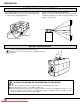
PREPARATION POSITIONING THE PROJECTOR ● This projector is basically designed to project on a flat projection surface. ● This projector can be focused from 4.9' (1.5 m) ~ 80.7' (24.6 m). ● Refer to the figure below as an example when positioning the projector to the screen. THIS PROJECTOR SHOULD BE SET IN THE WAY INDICATED. NEVER HANG THE PROJECTOR, OR FALL DOWN ON ITS SIDE. IT MAY RESULT IN FIRE HAZARD. ROOM LIGHT Maximum Zoom Minimum Zoom The projector should be placed in a room with limited light.
PREPARATION PICTURE LEVEL AND TILT ADJUSTMENT MOVE THE PROJECTED IMAGE POSITION Adjust the projected image position (maximum 760mm downward or upward on the 100" screen) by using lens shift function. (See page 33.) 760 mm Picture tilt and projection angle can be adjusted by twisting ADJUSTABLE FEET. Projection angle can be adjusted up to 4 degrees by rotating Adjustable Feet. 100" SCREEN DOWN UP 760 mm DOWN UP ADJUSTABLE FEET MOVING THE PROJECTOR Use the carry handle when moving the projector.
CONNECTING THE PROJECTOR TERMINAL OF THE PROJECTOR 9 8 10 USB 1 11 USB 2 6 CONTROL PORT 1 AUDIO 1 R CONTROL PORT 2 13 SERIAL PORT 12 L 2 ANALOG DIGITAL (MONO) AUDIO 2 R R/C JACK 1 5 L (MONO) R G B AUDIO OUT R ANALOG RGB L H V COMPUTER OUT COMPUTER IN-2 COMPUTER IN-1 SIDE OF THE PROJECTOR (CONNECT THE COMPUTER) 3 4 7 1 COMPUTER INPUT-1 TERMINAL (ANALOG HDB 15-PIN) Used to connect a computer to the projector.
CONNECTING THE PROJECTOR SIDE OF THE PROJECTOR (CONNECT THE VIDEO EQUIPMENT) 15 16 VIDEO IN-1 14 18 VIDEO/Y C/Cb(B-Y) Cr(R-Y) S-VIDEO AUDIO R L (MONO) 19 20 MONITOR OUT VIDEO IN-2 17 VIDEO/Y C/Cb(B-Y) Cr(R-Y) S-VIDEO AUDIO R L (MONO) 22 VIDEO/Y C/Cb(B-Y) Cr(R-Y) S-VIDEO AUDIO R L 21 14 VIDEO INPUT JACKS-1 (BNC TYPE x 3) Used to connect a video source to the projector. 19 AUDIO INPUT JACKS-2 (R and L) Used to connect an audio source to the projector.
CONNECTING THE PROJECTOR CONNECTING THE COMPUTER CONNECTING TO THE COMPUTER INPUT 1 TERMINAL (ANALOG HDB 15-PIN) Personal computers can be connected to the HDB15-pin (VGA) terminal on the projector. ● Connect the computer to these terminals using the VGA cable and VGA/MAC adapter (provided). CAUTION: For projectors, the VGA cable provided is designed to reduce RFI (Radio Frequency Interference) emissions.
CONNECTING THE PROJECTOR CONNECTING TO THE MONITOR OUTPUT TERMINAL (ANALOG HDB 15-PIN) This terminal output the information of the selected computer source being viewed on the screen (Computer 1 or Computer 2). When video source ("Video 1" or "Video 2") is selected, this terminal outputs Computer 1 input information. An external monitor can be connected to the HDB15-pin (VGA) terminal on the projector. ● Connect the monitor to this terminal using the VGA cable (not provided).
CONNECTING THE PROJECTOR CONNECTING AN IBM-COMPATIBLE DESKTOP COMPUTER MONITOR CABLE (NOT PROVIDED) COMPUTER BNC CABLE x 5 (NOT PROVIDED) COMPUTER OUTPUT (BNC TYPE x 5) VGA CABLE (PROVIDED) COMPUTER OUTPUT (HDB15-PIN TYPE) COMPUTER AUDIO OUTPUT PS/2 PORT INPUT R L COMPUTER AUDIO INPUT 1 or 2 R USB 1 CONTROL PORT 1 COMPUTER INPUT 1 (ANALOG) L AUDIO 1 R MOUSE CABLE FOR PS/2 PORT (PROVIDED) USB 2 CONTROL PORT 2 MOUSE CABLE FOR SERIAL PORT (PROVIDED) SERIAL PORT L DIGITAL ANALOG (MONO) AU
CONNECTING THE PROJECTOR CONNECTING AN IBM-COMPATIBLE DESKTOP COMPUTER (DIGITAL INPUT CONNECTION) NOTE: This connection need optionally sold Graphic Accelerator Board. For this information, contact to your authorized dealer. Before using with digital connection, install (Plug in) Graphic Accelerator Board into PCI bus slot of the computer and set up the computer following instructions in the Graphic Accelerator Board package.
CONNECTING THE PROJECTOR CONNECTING AN IBM-COMPATIBLE LAPTOP COMPUTER COMPUTER VGA CABLE (PROVIDED) COMPUTER OUTPUT (DB15-PIN TYPE) AUDIO CABLE (NOT PROVIDED) R SERIAL PORT INPUT COMPUTER AUDIO OUTPUT PS/2 PORT INPUT L USB 1 R CONTROL PORT 1 L AUDIO 1 R MOUSE CABLE FOR PS/2 PORT (PROVIDED) USB 2 CONTROL PORT 2 MOUSE CABLE FOR SERIAL PORT (PROVIDED) R/C JACK SERIAL PORT OUTPUT SERIAL PORT CABLE (NOT PROVIDED) SERIAL PORT L ANALOG L DIGITAL (MONO) AUDIO 2 R CONTROL PORT OUTPUT 1 COMPU
CONNECTING THE PROJECTOR CONNECTING AN IBM-COMPATIBLE LAPTOP COMPUTER (DIGITAL INPUT CONNECTION) NOTE: This connection need optionally sold Graphic Accelerator PC card. For this information, contact to your authorized dealer. Before using with digital connection, install (Plug in) Graphic Accelerator PC card into card bus slot of the computer and set up the computer following instructions in the Graphic Accelerator PC card package.
CONNECTING THE PROJECTOR CONNECTING A MACINTOSH DESKTOP COMPUTER COMPUTER MONITOR CABLE (NOT PROVIDED) BNC CABLE x 5 (NOT PROVIDED) COMPUTER OUTPUT (BNC TYPE x 5) ADB PORT INPUT VGA CABLE (PROVIDED) R COMPUTER AUDIO OUTPUT L AUDIO CABLE (NOT PROVIDED) R COMPUTER AUDIO OUTPUT1 or 2 USB 1 L CONTROL PORT 1 AUDIO 1 R USB 2 CONTROL PORT 2 MOUSE CABLE FOR ADB PORT (PROVIDED) SERIAL PORT L L DIGITAL ANALOG (MONO) AUDIO 2 R R/C JACK COMPUTER INPUT 1 (ANALOG) (MONO) R G B H V AUDIO OUT
CONNECTING THE PROJECTOR CONNECTING A MACINTOSH POWERBOOK COMPUTER NOTE: The Macintosh PowerBook requires the use of the PowerBook Video Adapter shipped with the PowerBook.
CONNECTING THE PROJECTOR CONNECTING THE VIDEO EQUIPMENT CONNECTING TO THE VIDEO INPUT JACKS (1 and 2) BNC TYPE x 3 Connect to the video outputs of a VCR, video disc player, DVD player, video camera, satellite TV tuner or other AV equipment. Connect video output from AV equipment to these jacks using the BNC cables. The video input can be connected 3 types of signals; “COMPOSITE VIDEO", "Y/C SEPARATE VIDEO" and COMPONENT VIDEO {Y, Cb (B-Y), Cr (R-Y)}.
CONNECTING THE PROJECTOR CONNECTING THE VIDEO EQUIPMENT VIDEO EQUIPMENT Video Cassette Recorder Y OUTPUT (BNC) C Cb (B-Y) OUTPUT OUTPUT (BNC) (BNC) MONITOR OUT VIDEO IN-2 VIDEO IN-1 VIDEO OUTPUT (BNC) DVD Player Video Disc Player VIDEO INPUT (BNC) Y C INPUT INPUT (BNC) (BNC) VIDEO/Y Cr (R-Y) OUTPUT (BNC) C/Cb(B-Y) Cr(R-Y) Satellite TV Tuner S-VIDEO OUTPUT S-VIDEO Video Camera AUDIO OUTPUT AUDIO R VIDEO/Y C/Cb(B-Y) Cr(R-Y) S-VIDEO Cb (B-Y) INPUT (BNC) C/Cb(B-Y) Cr(R-Y) S-VIDEO L
BEFORE OPERATION CONTROLS AND INDICATORS FRONT INDICATORS TOP CONTROLS FRONT INDICATORS 2 1 3 4 LAMP READY LAMP REPLACE TOP CONTROLS WARNING TEMP. 7 6 VOLUME ZOOM MODE MENU 8 9 FOCUS LENS SHIFT ON-OFF 5 14 10 AUTO IMAGE NORMAL SELECT 11 12 Downloaded From projector-manual.
BEFORE OPERATION 1 LAMP REPLACEMENT INDICATOR Light is orange when the Lamp life draws to an end. 2 TEMPERATURE WARNING INDICATOR Flashes red when internal projector temperature is too high. 3 READY INDICATOR Light is green when projector lamp is ready to be turned on. 4 LAMP POWER INDICATOR Light is dim when the projector is on. Light is brightened when the projector is in stand-by mode. 5 VOLUME BUTTONS Used to adjust volume. 6 ZOOM BUTTONS Used to operate power zoom lens.
BEFORE OPERATION OPERATION OF THE REMOTE CONTROL WIRELESS REMOTE CONTROL UNIT This remote control unit is not only able to operate the projector but also usable as a wireless mouse for a PC. One pointing pad and two click buttons are used for wireless mouse operation. Wireless mouse is usable when PC mouse pointer is displayed on the screen. When the menu or indicator of the projector is displayed on the screen instead of the PC mouse pointer, the wireless mouse cannot be used.
BASIC OPERATION 1 2 3 4 5 6 7 8 9 10 11 12 13 14 15 16 17 18 19 26 COMPUTER SELECT BUTTON Used to select computer mode. (Computer 1 or Computer 2 Input) VIDEO SELECT BUTTON Used to select video mode. (Video 1 or Video 2 Input) POWER ON/OFF BUTTON Used to turn the projector on or off. VOLUME BUTTONS Used to adjust volume. ZOOM BUTTON Used to select power zoom lens adjust. P-TIMER BUTTON Used to operate the P-TIMER function. FOCUS BUTTON Used to select focus adjust.
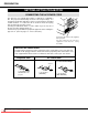
BEFORE OPERATION Remote Control Battery Installation 1 2 Remove the battery compartment lid. Slide the batteries into the compartment. 3 Replace the compartment lid. Note : For correct polarity (+ and terminal), be sure the battery terminals are in contact with the pins in the compartment. Using the Remote Control Unit Point the remote control toward the projector (Receiver window) whenever pressing the buttons. Maximum operating range for the remote control is about 16.
BEFORE OPERATION WIRELESS/WIRED REMOTE CONTROL UNIT 1 2 3 4 5 WIRED REMOTE JACK When using the wired remote control, connect the remote cable to this jack. 1 COMPUTER SELECT BUTTON Used to select computer mode. (Computer 1 or Computer 2 Input) 3 VIDEO SELECT BUTTON Used to select video mode. (Video 1 or Video 2 Input) 2 POWER ON/OFF BUTTON Used to turn projector on or off. 5 6 9 COMPUTER VIDEO VOLUME BUTTONS Used to adjust volume.
BEFORE OPERATION Remote Control Battery Installation 1 Remove the battery compartment lid. 2 3 Slide the batteries into the compartment. Replace the compartment lid. Note : For correct polarity (+ and terminal), be sure the battery terminals are in contact with the pins in the compartment. OPEN OPEN The remote control unit can be used as wireless or wired remote control.
BEFORE OPERATION OPERATING ON-SCREEN MENU HOW TO OPERATE ON-SCREEN MENU You can control and adjust this projector through the ON-SCREEN MENU. Refer to the following pages to operate each adjustment in the ON-SCREEN MENU. WIRELESS REMOTE CONTROL 1 MOVING THE POINTER POINT BUTTON Used to move the Pointer UP/ DOWN/ RIGHT/ LEFT. Move the pointer (see the NOTE below) by pressing POINT button(s) on the TOP CONTROL or on the REMOTE CONTROL.
BEFORE OPERATION MENU BAR MENU BAR IN COMPUTER MODE AUTO IMAGE MENU PC ADJUST MENU Used to adjust Fine sync, Total dots, and Picture Position automatically. (Refer to P41) Used to adjust the parameters to match with the input signal format. (Refer to P38, 39) MODE MENU Used to select the Computer input mode. (Refer to P36) Press MENU BUTTON while in Computer mode. SETTING MENU Used to set the Display Menu and reset Lamp Replacement Monitor Timer.
BASIC OPERATION TURNING ON/OFF THE PROJECTOR TO TURN ON THE PROJECTOR Connect the projector to a source (Computer, VCR, Video Camera, Video Disc Player, etc.) using the appropriate terminals on the side of the projector (See "CONNECTING THE PROJECTOR" section on pages 13-22). Connect the projector's AC power cord into a wall outlet and turn the MAIN ON/OFF switch (located on the side of the projector) to the ON position. The LAMP POWER indicator will light RED, the READY indicator will light GREEN.
BASIC OPERATION ADJUSTING THE IMAGE ZOOM ADJUSTMENT Use Top control and Wireless/Wired remote control unit. Press the ZOOM (▲) or (▼) button to obtain your desired picture size. For a larger picture, press (▲) and for a smaller picture, press (▼). Use Wireless remote control unit. Press the ZOOM button and press POINT UP/DOWN button(s) to obtain your desired picture size. The Zoom display will be displayed on the screen for a few seconds.
BASIC OPERATION FREEZE PICTURE FUNCTION Press the FREEZE/NO SHOW button on the remote control unit, and the picture will remain on-screen. This function is cancelled when the FREEZE/NO SHOW button is pressed again or any other button is pressed. NOTE: Your computer or video equipment is not affected by this function, and will continue to run. NO SHOW FUNCTION Press the FREEZE/NO SHOW button (on the remote control unit) is twice.
BASIC OPERATION SOUND ADJUSTMENT DIRECT OPERATION Indicates the roughly level of the volume. Sound Volume Adjustment Press the VOLUME (+/–) button(s) on the Top Control or on the Remote Control Unit to adjust the volume. The Volume dialog box appears on the screen for a few seconds. (+) button to increase the volume, and (–) button decreasing. Sound Mute Setting Press the MUTE button on the Remote Control Unit to cut off the sound.
COMPUTER MODE SELECTING COMPUTER MODE DIRECT OPERATION Press the MODE button on the projector or the COMPUTER button on the remote control unit to select Computer 1, Computer 2 Input. The "Computer 1", or "Computer 2" display will appear on the screen for a few seconds. MODE button COMPUTER button Computer 1 Computer 1 Computer 2 Computer 2 Video 1 Video 2 MENU OPERATION 1 Press the MENU button and the ON-SCREEN MENU will appear.
COMPUTER MODE COMPATIBLE COMPUTER SPECIFICATIONS ON-SCREEN RESOLUTION DISPLAY H-Freq. (kHz) V-Freq. (Hz) ON-SCREEN RESOLUTION DISPLAY H-Freq. (kHz) V-Freq. (Hz) VGA1 640 x 480 31.47 59.88 XGA14 1024 x 768 47.00 58.30 VGA2 720 x 400 31.47 70.09 XGA15 1024 x 768 58.03 72.00 VGA3 640 x 400 31.47 70.09 MAC19 1024 x 768 60.24 75.08 VGA4 640 x 480 37.86 74.38 SXGA1 1152 x 864 64.20 70.40 VGA5 640 x 480 37.86 72.81 SXGA2 1280 x 1024 62.50 58.60 VGA6 640 x 480 37.
COMPUTER MODE PC ADJUSTMENT This Projector can automatically tune to the display signals from most personal computers currently distributed. However, some computers employ special signal formats which are different from the standard ones and may not be tuned by the Multi-Scan system of this projector. If this happens, the projector cannot reproduce a proper image and the image may be recognized as a flickering picture, a non-synchronized picture, a non-centered picture or a skewed picture.
COMPUTER MODE Total lines The number of the total vertical lines. Adjust the number to match the image of your personal computer. Total dots The number of the total dots in one horizontal period. Adjust the number to match the image of your computer. Horizontal / Vertical Adjustment of the horizontal or vertical picture position. When the image is not centered on the screen, adjust each of those items. Clamp Adjustment of the clamp level. When the image has a dark bar(s), try this adjustment.
COMPUTER MODE PICTURE IMAGE ADJUSTMENTS 1 Press the MENU button and the ON-SCREEN MENU will appear. Press the POINT LEFT/RIGHT buttons to select IMAGE and press the SELECT (REAR CLICK) button. Another dialog box PICTURE IMAGE ADJUSTMENT Menu will appear. 2 Press the POINT DOWN button and a red-arrow icon will appear. Move the arrow to the function that you want to select and then press SELECT (REAR CLICK) button. Fine sync Adjust the picture as necessary to eliminate flicker from the display.
COMPUTER MODE NORMAL FUNCTION The normal picture level is preset on this projector at the factory and can be restored anytime you press the NORMAL button (located on the Top Control or on the Remote Control Unit). The “Normal” display will be displayed on the screen for a few seconds. Normal AUTO IMAGE ADJUSTMENT The Auto Image adjustment is provided to automatically adjust Fine sync., Total dots, and Picture Position for most computers. 1 Press the MENU button and the ON-SCREEN MENU will appear.
COMPUTER MODE PICTURE POSITION ADJUSTMENT The position of the image can be adjusted vertically and horizontally through PICTURE POSITION ADJUSTMENT. 1 Press the MENU button and the ON-SCREEN MENU will appear. Press the POINT LEFT/RIGHT buttons to select POSITION and press the SELECT (REAR CLICK) button. The PICTURE POSITION dialog box will appear.
COMPUTER MODE PICTURE SCREEN ADJUSTMENT This projector has a picture screen resize function, which enables you to display the desirable image size. 1 Press the MENU button and the ON-SCREEN MENU will appear. Press the POINT LEFT/RIGHT buttons to select SCREEN and press the SELECT (REAR CLICK) button. Another dialog box PICTURE SCREEN Menu will appear. 2 Press the POINT DOWN button and a red-arrow icon will appear.
VIDEO MODE SELECTING VIDEO MODE DIRECT OPERATION Press the MODE button on the projector or the VIDEO button on the remote control unit to select Video 1, Video 2 Input. The "Video 1", or "Video 2" display will appear on the screen for a few seconds. MENU OPERATION 1 Press the MENU button and the ON-SCREEN MENU will appear. Press the POINT LEFT/RIGHT buttons to select Computer and press the SELECT (REAR CLICK) button. Another dialog box VIDEO MODE Menu will appear.
VIDEO MODE SELECTING COLOR SYSTEM 1 Press the MENU button and the ON-SCREEN MENU will appear. Press the POINT LEFT/RIGHT buttons to select SYSTEM and press the SELECT (REAR CLICK) button. Another dialog box VIDEO SYSTEM Menu will appear. 2 Press the POINT DOWN button and a red-arrow icon will appear. Move the arrow to "Auto", and then press the SELECT (REAR CLICK) button.
VIDEO MODE PICTURE IMAGE ADJUSTMENT 1 Press the MENU button and the ON-SCREEN MENU will appear. Press the POINT LEFT/RIGHT buttons to select IMAGE and press the SELECT (REAR CLICK) button. Another dialog box PICTURE IMAGE ADJUSTMENT Menu will appear. 2 Press the POINT DOWN button and a red-arrow icon will appear. Move the arrow to the function that you want to select and then press SELECT (REAR CLICK) button. Move the arrow to ▲ or ▼ and press SELECT (REAR CLICK) button.
VIDEO MODE NORMAL FUNCTION The normal picture level is preset on this projector at the factory and can be restored anytime you press the NORMAL button (located on the Top Control or on the Remote Control Unit). The "Normal" display will be displayed on the screen for a few seconds. Normal PICTURE SCREEN ADJUSTMENT This projector has a picture screen resize function, which enables you to display the desirable image size. 1 Press the MENU button and the ON-SCREEN MENU will appear.
SETTING SETTING MENU 1 Press the MENU button and the ON-SCREEN MENU will appear. Press the POINT LEFT/RIGHT buttons to select SETTING and press the SELECT (REAR CLICK) button. Another dialog box SETTING Menu will appear. 2 Press the POINT DOWN button and a red-arrow icon will appear. Move the arrow to the item that you want to set, and then press the SELECT (REAR CLICK) button to set it "On" or "Off" or press the POINT LEFT/RIGHT button to adjust the value.
SETTING USB This Projector is equipped with USB port for interactive operation between the projector and the computer. Set the mode following steps below. Wireless Mouse mode Select " " when controlling the computer with the Remote Control of this projector. Projector mode Select " " when controlling the projector with the computer. NOTE: Before you control the projector by computer, install USB driver (optionally sold parts) and set up the computer following instruction in the USB driver package.
APPENDIX OPERATING WIRELESS MOUSE The Wireless Remote Control Unit is not only able to operate the projector but also usable as a wireless mouse for most Personal Computers. The POINT buttons and the two CLICK buttons are used for the wireless mouse operation. The wireless mouse is available only when PC mouse pointer is displayed on the screen. When the menu or the indicator of the projector is displayed on the screen instead of the PC mouse pointer, the wireless mouse cannot be used.
APPENDIX MAINTENANCE TEMPERATURE WARNING INDICATOR The TEMPERATURE WARNING INDICATOR flashes red when the internal temperature of the projector exceeds the normal temperature. Possible causes for the temperature warning may be : 1. Ventilation slots of the projector are blocked. In such an event, reposition the projector so that ventilation slots are not obstructed. 2. Air filter is clogged with dust particles.
APPENDIX LAMP REPLACEMENT WHEN THE PROJECTION LAMP OF THIS PROJECTOR DRAWS TO AN END, THE LAMP REPLACEMENT INDICATOR LIGHTS YELLOW AND THE WARNING MESSAGE "LAMP REPLACEMENT" APPEARS AS THE RIGHT FIGURE. WHEN THE WARNING MESSAGE IS DISPLAYED, THE PROJECTION LAMP SHOULD BE REPLACED. To terminate the warning message. Replace the Projection Lamp and reset the LAMP REPLACEMENT MONITOR TIMER (See "LAMP REPLACEMENT MONITOR TIMER" section on page 49.), and the warning message is terminated.
APPENDIX CLEANING THE PROJECTION LENS Follow these steps to clean the projection lens: 1. Apply a non-abrasive camera lens cleaner to a soft, dry cleaning cloth. Avoid using an excessive amount of cleaner. Abrasive cleaners, solvents or other harsh chemicals might scratch the lens. 2. Lightly wipe the cleaning cloth over the lens. 3. When you don't use the projector, replace the lens cover. TROUBLESHOOTING Before calling your dealer or service station for assistance, check the matters below once again. 1.
APPENDIX Problem: Picture is T/B inverted. Try these Solutions: Check Reverse T/B feature. (See "SETTING" section on pages 48 ~ 49). Picture is L/R Reversed. Check Reverse L/R feature. (See "SETTING" section on pages 48 ~ 49). Some displays are not seen during the operation. Check Display feature. (See "SETTING" section on pages 48 ~ 49). ● ● ● ● No sound. Check audio cable connection from audio input source. Adjust audio source. Press the VOLUME (+) button. Press the MUTE button.
APPENDIX TECHNICAL SPECIFICATIONS Projector Type Multi-media Projector Dimensions (W x H x D) 15.4" (390 mm) x 9.6" (245 mm) x 23" (585 mm) Net Weight 39.2 Ibs (17.8 kg) LCD Panel System 1.8" TFT Active Matrix type x 3 panels Number of Pixels 2,359,296 {786,432 (1,024 x 768) x 3} Color System 6 color system (PAL, SECAM, NTSC, NTSC4.43, PAL-M and PAL-N) Scanning Frequency H-sync. 15 ~ 100 KHz, V-sync.
Audio Visual/Video Products EIKI INTERNATIONAL, INC. 26794 Vista Terrace Drive, Lake Forest, CA. 92630-8113, U.S.A. TEL (949) 457-0200 FAX (949) 457-7878 EIKI CANADA 865 Heritage Drive P.O. Box 156 Midland Ontario L4R 4K8 Canada TEL (705) 527-4084 FAX (705) 527-4087 EIKI DEUTSCHLAND GMBH AM Frauwald 12 65510 Idstein Germany TEL (6126) 9371-0 FAX (6126) 9371-11 EIKI CZECH SPOL. S.R.O. Umelccka 15, 170 00 Praha 7 Holesovice Czech Republic TEL (2) 20571413 FAX (2) 20571411 EIKI INDUSTRIAL CO.