MULTIMEDIA PROJECTOR MODEL LC-SD12 OWNER’S MANUAL
Features and Design This Multimedia Projector is designed with the most advanced technology for portability, durability, and ease of use. This projector utilizes built-in multimedia features, a palette of 16.77 million colors, and matrix liquid crystal display (LCD) technology. Greater Mobility Extremely compact in size and weight. It is designed to be carried and work anywhere you wish to use. Digital Zoom (for Computer) Digital zoom function expands (to approx.
Table of Contents Features and Design ............................................2 Table of Contents.................................................3 To the Owner .......................................................4 Safety Instructions...............................................5 Air Circulation . . . . . . . . . . . . . . . . . . . . . . . . . . . . . .6 Installing the Projector in Proper Position . . . . . . . . .6 Moving the Projector . . . . . . . . . . . . . . . . . . . . . . . . .
To the Owner Before operating this projector, read this manual thoroughly to operate the projector properly. This projector provides many convenient features and functions. Operating the projector properly enables you to manage those features and maintains it in better condition for a considerable time. Improper operation may result in not only shortening the product-life, but also malfunctions, a fire hazard, or other accidents.
Safety Instructions All the safety and operating instructions should be read before the product is operated. Read all of the instructions given here and retain them for later use. Unplug this projector from AC power supply before cleaning. Do not use liquid or aerosol cleaners. Use a damp cloth for cleaning. This projector should be operated only from the type of power source indicated on the marking label.
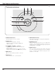
Safety Instruction Air Circulation Installing the Projector in Proper Position Openings in the cabinet are provided for ventilation and to ensure reliable operation of the product and to protect it from overheating, and these openings must not be blocked or covered. Install the projector properly. Improper Installation may reduce the lamp lifetime and cause a fire hazard. 20˚ Do not tilt the projector more than 20 degrees above and below. CAUTION Hot air is exhausted from the exhaust vent.
Compliance Federal Communication Commission Notice Note : This equipment has been tested and found to comply with the limits for a Class B digital device, pursuant to part 15 of the FCC Rules. These limits are designed to provide reasonable protection against harmful interference in a residential installation. This equipment generates, uses and can radiate radio frequency energy and, if not installed and used in accordance with the instructions, may cause harmful interference to radio communications.
Parts Names and Functions q Zoom Lever ( ☞ P20 ) w Infrared Remote Receiver ( ☞ P11 ) e Focus Ring ( ☞ P20 ) r Projection Lens ( ☞ P41 ) t Lens Cover ( ☞ P40 ) y Air Intake Vent ( ☞ P40 ) u Exhaust Vent Front q w CAUTION e r i Hot air is exhausted from the exhaust vent. Do not put heat-sensitive objects near this side.
Parts Name and Functions ✽ q w Part Names and Functions Terminals and Connectors e RESET VIDEO COMPUTER IN / COMPONENT IN/ S-VIDEO AUDIO IN SERVICE PORT USB COMPUTER / AV COMPONENT u y t r q VIDEO Connect the composite video output from video equipment. ( ☞ P16 ) t AUDIO IN AV Connect audio output from video equipment. ( ☞ P16 ) w S-VIDEO Connect S-video output from video equipment. ( ☞ P16 ) y AUDIO IN COMPUTER/ COMPONENT Connect audio output from a computer or component to this jack.
Parts Names and Functions Top Controls and Indicators i u y WARNING LAMP REPLACE POWER t q INPUT ON - OFF r SELECT LUME+ VO LUME– VO w MENU e q POWER ON-OFF button Turn the projector on or off. ( ☞ P17 ) w SELECT button – Execute the selected item. ( ☞ P18 ) – Expand / compress the image in Digital Zoom mode. ( ☞ P29 ) e Point ed7 8 ( VOLUME + / – ) buttons – Select an item or adjust the value in the On-Screen Menu. ( ☞ P18 ) – Pan the image in Digital zoom +/– mode.
Parts Name and Functions Part Names and Functions q POWER ON-OFF button Turn the projector on or off. ( ☞ P17 ) Remote Control w VIDEO button Select VIDEO input source. ( ☞ P30 ) e w e COMPUTER button Select COMPUTER input source. ( ☞ P22, P31 ) q r MENU button Open or close the On-Screen Menu. ( ☞ P18 ) t PAGE ed buttons Scroll back and forth pages on the screen when giving a presentation. ( ☞ P9, P38 ) y D.ZOOM ed buttons Select the Digital zoom +/– mode and resize the image.
Parts Names and Functions Remote Control Battery Installation 1 Remove the battery compartment lid. Pull up and remove the lid. 2 Slide the batteries into the compartment. 3 Replace the compartment lid. Two AAA size batteries For correct polarity (+ and –), be sure battery terminals are in contact with pins in compartment. To insure safe operation, please observe the following precautions : – Use (2) AAA, SUM-4 or LR03 type alkaline batteries. – Replace two batteries at the same time.
Installation Positioning the Projector – This projector is designed to project on a flat projection surface. – The projector can be focused from 4.3’(1.3m) to 21.3’(6.5m). – Refer to the figure below to adjust the screen size. Note: The brightness in a room has a great influence on the picture quality. It is recommended to limit ambient lighting in order to provide the best image. A:B = 9:1 21.3’ (6.5m) 16.1’ (4.9m) 200” 10.6’ (3.2m) Max. Zoom Installation 150” Min. Zoom 4.3’ (1.
Installation Connecting the AC Power Cord This projector uses nominal input voltages of 100-120 V or 200-240 V AC. This projector automatically selects the correct input voltage. It is designed to work with single-phase power systems having a grounded neutral conductor. To reduce risk of electrical shock, do not plug into any other type of power system. Consult your authorized dealer or service station if you are not sure of the type of power supply being in use.
Installation Connecting to a Computer IBM-compatible computer or Macintosh computer (VGA / SVGA / XGA / SXGA) Monitor Output Audio Output USB port Installation Audio Cable (Stereo) ✽ VGA Cable USB Cable ✽ If you want to use the Page ▲▼ buttons on the remote control, connect USB port of your computer to the USB socket of the projector.
Installation Connecting to Video Equipment Video Source (example) Video Cassette Recorder Audio Output RGB Scart 21-pin Output Component video output equipment. (such as DVD player or Video Disc Player Component Video Output (Y, Pb/Cb, Pr/Cr) high-definition TV source.
Basic Operation Turning On the Projector 1 Complete peripheral connections (with a computer, VCR, etc.) before turning on the projector. 2 Connect the projector's AC Power Cord into an AC outlet. The POWER indicator flashes in a moment and then turns red. 3 Press the POWER ON-OFF button on the top control or on the remote control. The POWER indicator turns green, and the cooling fans start to operate. The starting display appears on the screen and the count-down starts.
Basic Operation How to Operate the On-Screen Menu Menu bar The projector can be adjusted or set via the On-Screen Menu. Refer to the following pages regarding each adjustment and setting procedure. 1 Press the MENU button to display the On-Screen Menu. 2 Press the Point7 8 buttons to select a Menu icon to adjust. Press the Pointed buttons to select an item to adjust. 3 Press the SELECT button to show the item data. Press the Point7 8 buttons to adjust the data.
Basic Operation Menu Bar For Computer Source Guide Window PC System Menu Image Select Menu Screen Menu Setting Menu Shows the selected item of the OnScreen Menu. Used to select the computer system. ( ☞ P23 ) Used to select an image level among Standard, Real, and Image 1 – 4. ( ☞ P27 ) Used to adjust the size of image. [Normal / True / Wide / Digital zoom +/–] ( ☞ P29 ) Used to change settings of the projector or reset the Lamp replace counter.
Basic Operation Zoom Adjustment Tele Move the Zoom Lever upward / downward to zoom the image. Wide Zoom Lever Focus Adjustment Rotate the Focus Ring to adjust the projected picture focus. Focus Ring Keystone Adjustment If a projected picture has keystone distortion, correct image with the Keystone adjustment. 1 Press the KEYSTONE button on the remote control or select Keystone on the Setting menu ( ☞ P36 ) to display the Keystone dialog box.
Basic Operation No Show Function Press the NO SHOW button on the remote control to black out the image. To restore to normal, press the NO SHOW button again or press any other button. When a projected image is captured and set as “User” in the Logo item in the Setting menu ( ☞ P36 ), the screen changes each time you press the NO SHOW button as follows : black out ➜ the captured image ➜ normal ➜...... Message disappears after 4 seconds. P-Timer Function Press the P-TIMER button on the remote control.
Computer Input Input Source Selection INPUT button Computer Direct Operation Choose Computer by pressing the INPUT button on the top control or the COMPUTER button on the remote control. Before using these buttons, correct input source should be selected through menu operation as described below. Video Menu Operation Input Menu icon 1 Press the MENU button to display the On-Screen Menu. Press the Point 7 8 buttons to move the red frame pointer to Input Menu icon.
Computer Input Computer System Selection This projector automatically tunes to various types of computers based on VGA, SVGA, XGA or SXGA with its Multi-scan system and Auto PC Adjustment. If Computer is selected as a signal source, this projector automatically detects the signal format and tunes to project a proper image without any additional setting. (Signal formats provided in this projector is shown on page 49 ) Note : The projector may display one of the following messages.
Computer Input Auto PC Adjustment Auto PC Adjustment function is provided to automatically conform Fine sync, Total dots and Picture Position to your computer. This function can be operated as follows. Auto PC Adj. 1 Press the MENU button to display the On-Screen Menu. Press the Point 7 8 buttons to move the red frame pointer to the PC Adjust Menu icon. 2 Press the Point d button to move the red frame pointer to the Auto PC Adj. icon and then press the SELECT button twice.
Computer Input Manual PC Adjustment Some computers employ special signal formats which may not be tuned by Multi-Scan system of this projector. In this case, the projector cannot reproduce a proper image and the image may be recognized as a flickering picture, a nonsynchronized picture, a non-centered picture or a skewed picture. The Manual PC Adjustment function allows you to precisely adjust several parameters to match those special signal formats.
Computer Input Display area Select area displayed with this projector. Select the resolution at the Display area dialog box. Display area H Press the SELECT button at the Display area icon to show the Display area dialog box. Adjust the horizontal area displayed with this projector. Press the Point 7 8 buttons to decrease/increase value to match the resolution of image. Then press the SELECT button. Display area Display area V Adjust the vertical area displayed with this projector.
Computer Input Image Level Selection Direct Operation Select image level among Standard, Real, Image 1, Image 2, Image 3 and Image 4 by pressing the IMAGE button on the remote control. IMAGE button Standard Real Standard Normal picture adjustment preset on this projector. Image 1 Real Picture adjustment improved in reproduction of halftones. This adjustment is suitable for providing better image in brighter place. Image 1~4 User preset picture adjustment in Image Adjust Menu ( ☞ P28 ).
Computer Input Image Level Adjustment 1 2 Press the MENU button to display the On-Screen Menu. Press the Point 7 8 buttons to move the red frame pointer to the Image Adjust Menu icon. Press the Point d button to move the red frame pointer to the item that you want to adjust, and then press the SELECT button. The level of each item is displayed. Adjust each level by pressing the Point 7 8 buttons.
Computer Input Screen Size Adjustment This projector has a picture screen resize function, which enables you to customize the image size. 1 Press the MENU button to display the On-Screen Menu. Press the Point 7 8 buttons to move the red frame pointer to the SCREEN MENU Screen Menu icon. 2 Press the Point d button to move the red frame pointer to the function that you want to select. Then press the SELECT button. Screen Menu icon Move the red frame to the function and press the SELECT button.
Video Input Input Source Selection ( Video, S-Video ) INPUT button Video Direct Operation Choose Video by pressing the INPUT button on the top control or the VIDEO button on the remote control. Before using these buttons, correct input source should be selected through menu operation as described below. Computer Menu Operation 1 Press the MENU button to display the On-Screen Menu. Press the Point 7 8 buttons to move the red frame pointer to the Input Menu icon.
Video input Input Source Selection ( Component, RGB Scart 21-pin ) INPUT button Video Direct Operation Choose Computer by pressing the INPUT button on the top control or the COMPUTER button on the remote control. Before using these buttons, correct input source should be selected through menu operation as described below. Computer Menu Operation 1 Press the MENU button to display the On-Screen Menu. Press the Point 7 8 buttons to move the red frame pointer to the Input Menu icon.
Video Input Video System Selection 1 Press the MENU button to display the On-Screen Menu. Press the Point 7 8 buttons to move the red frame pointer to the AV System Menu icon. 2 Press the Point d button to move the red arrow pointer to the system that you want to select and then press the SELECT button. Video Jack or S-Video Jack Auto The projector automatically detects incoming video system, and adjusts itself to optimize its performance.
Video Input Image Level Selection Direct Operation Select image level among Standard, Cinema, Image 1, Image 2, Image 3 and Image 4 by pressing the IMAGE button on the remote control. Standard Normal picture adjustment preset on this projector. Cinema Picture level adjusted for the picture with fine tone. Image 1~4 User preset picture adjustment in Image Adjust Menu ( ☞ P34-35 ).
Video Input Image Level Adjustment 1 Press the MENU button to display the On-Screen Menu. Press the Point 7 8 buttons to move the red frame pointer to the Image Adjust Menu icon. 2 Press the Point d button to move the red frame pointer to the item you want to adjust and then press the SELECT button. The level of each item is displayed. Adjust each level by pressing the Point 7 8 buttons. IMAGE ADJUST MENU Move the red frame pointer to the item to be selected and then press the SELECT button.
Video Input Auto grayscale When this function is "On", it automatically enhances contrast of bright and dark part of image. progressive Interlace video signal can be displayed in a progressive picture. Off ···· Not activated. L1 ···· Select “L1” for an active picture. L2 ···· Select “L2” for a still picture. Note : The Progressive cannot be selected when 1080i, 1035i, 720p, 575p, or 480p is selected. Reset Reset all adjustments to previous figures.
Setting Setting Menu 1 Press the MENU button to display the On-Screen Menu. Press the Point 7 8 buttons to move the red frame pointer to the SETTING icon. 2 Press the Point d button to move the red frame pointer to the item that you want to set. Then press the SELECT button to display the Setting dialog box. SETTING MENU Set the red frame pointer to the item and press the SELECT button.
Setting Ceiling Ceiling function When this function is “On”, picture is top / bottom and left / right reversed. This function is used to project the image from a ceiling mounted projector. Setting Rear Rear function When this function is “On”, picture is left / right reversed. This function is used to project the image to a rear projection screen.
Setting Remote control This projector has two different remote control codes; the factoryset normal code (Code 1) and the secondary code (Code 2). This switching function prevents remote control interference when operating several projectors or video equipment at the same time. When operating the projector in “Code 2,” both the projector and remote control must be switched to “Code 2.
Maintenance and Cleaning Warning Indicator The WARNING indicator shows the state of the function which protects the projector. Check the state of the WARNING indicator and the POWER indicator to take proper maintenance. The projector is shut down and the WARNING indicator is flashing red Note : After the temperature inside the projector returns to normal, the WARNING indicator still continues to flash. When the projector is turned on again, the WARNING indicator stops flashing.
Maintenance and Cleaning Air Filter Removable air filters prevent dust from accumulating on the surface of optical elements inside the projector. Should air filters become clogged with dust particles, it will reduce the cooling fans' effectiveness and may result in internal heat build up and adversely affect the life of the projector. Clean air filters following the steps below: 1 Turn off the projector, and disconnect AC power cord from the AC outlet.
Maintenance and Cleaning Cleaning the Projection Lens Follow these steps to clean the projection lens: Disconnect the AC power cord before cleaning. 2 Apply a non-abrasive camera lens cleaner to a soft, dry cleaning cloth. Avoid using an excessive amount of cleaner. Abrasive cleaners, solvents or other harsh chemicals might scratch a surface. 3 4 Lightly wipe Projection Lens with a cleaning cloth. Maintenance & Cleaning 1 When the projector is not in use, replace the Lens Cover.
Maintenance and Cleaning Lamp Replacement When the life of the projection lamp draws to an end, LAMP REPLACE indicator lights yellow. If this indicator lights yellow, replace the projection lamp with a new one promptly. TOP CONTROL WARNING POWER This indicator lights yellow when the life of the projection lamp draws to an end. LAMP REPLACE INPU CAUTION Allow the projector to cool, for at least 45 minutes before you open the Lamp Cover. The inside of the projector can become very hot.
Maintenance and Cleaning Lamp Replace Counter Be sure to reset the lamp replace counter after Lamp Assembly is replaced. When the lamp replace counter is reset, the LAMP REPLACE Indicator stops lighting. Setting Menu icon Turn projector on, press the MENU button to display the On-Screen Menu. Press the Point 7 8 buttons to move the red frame pointer to the Setting Menu icon. 2 Press the Point d button to move the red frame pointer to “Lamp counter reset” and then press the SELECT button.
Appendix Troubleshooting Before calling your dealer or service center for assistance, check the matters below once again. – Make sure you have properly connected the projector to peripheral equipment as described in the section "Installation" on P15-16. – Make sure all equipment is connected to AC outlet and turned on the power. – When you operate the projector with a computer, and it does not project an image, restart the computer. Problem: No power. Image is out of focus.
Appendix Problem: Remote Control does not work. – Try These Solutions – Check the battery. – Make sure nothing is between the infrared remote receiver and remote control. – Make sure you are not too far from the projector when using the remote control. Maximum operating range is 16.4’ ( 5m ). – Make sure the code of the remote control is set to conform to the projector. ( ☞ P38 ) – Unlock Key lock for the remote control in the Setting Menu.
Appendix Indicators and Projector Condition Check the indicators for projector condition. Indicators POWER WARNING LAMP REPLACE red/green red yellow Projector Condition The projector is OFF. (The AC power cord is unplugged.) • • • lights green. ✽ When ✽ The projector is preparing for stand-by or the projection lamp is being cooled down. The projector cannot be turned on until cooling is completed. ✽ The projector is ready to be turned on with the POWER ON-OFF button.
Appendix Menu Tree Main menu Input Computer RGB Go to System (1) Component Go to System (2) RGB( Scart ) Quit Video Auto Go to System (3) Video Go to System (3) S-Video Go to System (3) Quit Computer Input Main menu System (1) MODE 1 MODE 2 SVGA 1 ---- PC Adjust Auto PC Adj. Fine sync Total dots Horizontal Vertical Current mode Standard Real Image 1 Image 2 Image 3 Image 4 Image Adjust Contrast Brightness Color temp.
Appendix Video Input Settings Main menu Main menu Auto 1080i 1035i 720p 575p 480p 575i 480i System (2) System (3) Image Select Image Adjust Standard Cinema Image 1 Image 2 Image 3 Image 4 Contrast Brightness Color Tint Color temp.
Appendix Compatible Computer Specifications Basically this projector can accept the signal from all computers with the V, H-Frequency below mentioned and less than 100 MHz of Dot Clock. ON-SCREEN DISPLAY 640 x 480 720 x 400 640 x 400 640 x 480 640 x 480 640 x 480 640 x 480 640 x 480 640 x 480 –––––––– –––––––– –––––––– –––––––– 800 x 600 800 x 600 800 x 600 800 x 600 800 x 600 800 x 600 800 x 600 800 x 600 800 x 600 800 x 600 800 x 600 832 x 624 1024 x 768 H-Freq. (kHz) 31.47 31.47 31.47 37.86 37.86 37.
Appendix Technical Specifications Projector Type Dimensions (W x H x D) Net Weight LCD Panel System Panel Resolution Number of Pixels Color System High Definition TV Signal Scanning Frequency Projection Image size (Diagonal) Projection Lens Throw Distance Projection Lamp Video Input Jack Audio Input Jack Computer Input Terminal Computer Audio Input Jack Control Port Connector USB Connector Internal Audio Amp Built-in Speaker Feet Adjustment Voltage and Power Consumption Operating Temperature Storage Tempera
Appendix Configuration of Terminals COMPUTER INPUT TERMINAL (ANALOG) Terminal : Analog RGB (Mini D-sub 15-PIN) Pin Configuration 4 5 10 15 14 2 3 9 8 13 1 7 12 6 11 1 2 3 4 5 6 7 8 R / Cr, Pr Input G / Y Input B / Cb, Pb Input No Connect Ground (Horiz.sync.) Ground (Red) Ground (Green) Ground (Blue) 9 10 11 12 13 14 15 No Connect Ground (Vert.sync.) Ground No Connect Horiz. sync. Vert. sync.
A-key to better communications U.S.A. Canada EIKI International, Inc. 30251 Esperanza Rancho Santa Margarita CA 92688-2132 U.S.A. Tel : 800-24-3454 (949)-457-0200 Fax : 800-457-3454 (949)-457-7878 E-Mail : usa@eiki.com EIKI CANADA - Eiki International, Inc. P.O. Box 156, 310 First St. - Unit 2, Midland, ON, L4R 4K8, Canada Tel : 800-563-3454 (705)-527-4084 Fax : 800-567-4069 (705)-527-4087 E-Mail : canada@eiki.