
Manual


GB
- 23 -
chine and return the drill to its starting position.
6.3 Handling the keyless chuck
Your pillar drill is equipped with a keyless chuck.
This enables tools to be changed without the
need for an additional chuck key. To do so, insert
the tool in the quick-change drill chuck and tigh-
ten by hand.
6.4 Setting the speed (Fig. 1)
The operating speed of the machine is infi nitely
adjustable.
Important!
•
Speed adjustments are allowed only
when the motor is running.
•
Slowly and steadily move the speed con-
trol lever (15) while the machine is in idle
mode.
•
Ensure that the machine can run without
interruption (i.e. remove workpieces, drill
bits, etc.).
Use the speed control lever to infi nitely adjust the
speed. The set speed is shown on the digital dis-
play (17) in revolutions per minute.
Important! Never let the pillar drill run when the
V-belt cover is open. Always pull power plug befo-
re opening the cover. Never touch the V-belt when
it is rotating.
6.5 Drill depth stop point (Fig. 17)
The drilling spindle has a swiveling scale ring for
setting the drill depth. Only adjust the settings
when the equipment is at a standstill.
•
Press the drilling spindle (11) downwards until
the tip of the drill bit touches the workpiece.
•
Slacken the clamping screw (14) and turn the
scale ring (25) forwards until it stops.
•
Turn the scale ring (25) back to the desired
drill depth, then lock this setting into place
using the clamping screw (14).
6.6 Setting the angle of the drill table
(Fig. 1)
•
Slacken the carriage bolt (26) under the drill
table (4).
•
Set the drill table (4) to the desired angle.
•
Tighten down the carriage bolt (26) in order to
lock the drill table (4) into this position.
6.7 Setting the height of the drill table
(Fig. 19)
•
Slacken the tightening screw (30).
•
Manually move the drill table (4) into the re-
quired position.
•
Retighten the tightening screw.
6.8 Clamping the workpiece
As a general rule, use a machine vice or another
suitable clamping device to secure a workpiece in
position. Never hold the workpiece in place with
your hand! When drilling, the workpiece should
be able to travel on the drill table (4) for self-
centering purposes. Ensure that the workpiece
cannot rotate. This is best achieved by placing the
workpiece /machine vice on a sturdy block.
Caution! Sheet metal parts must be clamped in
to prevent them from being torn up. Properly set
the height and angle of the drill table for each
workpiece. There must be enough distance bet-
ween the upper edge of the workpiece and the tip
of the drill bit.
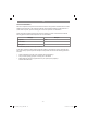
6.9 Working speeds
Ensure that you drill at the proper speed. Drill
speed is dependent on the diameter of the drill bit
and the material in question.
The table below acts as a guide for selecting the
proper speed for various materials.
Note: The drill speeds specifi ed are merely
suggested values.
Drill bit Ø Cast iron Steel Iron Aluminium Bronze
3 2550 1600 2230 9500 8000
4 1900 1200 1680 7200 6000
5 1530 955 1340 5700 4800
6 1270 800 1100 4800 4000
7 1090 680 960 4100 3400
8 960 600 840 3600 3000
9 850 530 740 3200 2650
10 765 480 670 2860 2400
11 700 435 610 2600 2170
12 640 400 560 2400 2000
13 590 370 515 2200 1840
14 545 340 480 2000 1700
16 480 300 420 1800 1500
18 425 265 370 1600 1300
20 380 240 335 1400 1200
22 350 220 305 1300 1100
25 305 190 270 1150 950
6.10 Countersinking and center-drilling
With this table drill, you can also countersink and
center-drill. Please observe that countersinking
should be performed at the lowest speed, while a
high speed is required for center-drilling.
Anl_TE_BD_550_E_SPK9.indb 23Anl_TE_BD_550_E_SPK9.indb 23 16.06.2020 12:46:3816.06.2020 12:46:38