
User Manual


Welcome Page 8 of 54
file://C:\TEMP\~hhA856.htm 8/12/02
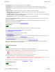
b. Using four screws, attach one foot to the bottom end of one leg (the end without crossbar holes). Attach two casters to each
foot. Insert three end caps (two on the foot and one on the leg). Repeat for the other foot and leg.
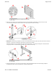
c. IMPORTANT: Examine the leg assemblies: one side of each assembly has 10 holes (2 groups of 5) and the other side has 8 holes (2
groups of 4). In this step, the sides with 10 holes must face away from the crossbars.
Attach both crossbars to one leg assembly using eight screws as shown below. The screws pass through the 4 outermost holes in
each group of 5 holes. Attach the other leg assembly to the crossbars in the same way.
d. Thread two thumbscrews (A) into each leg as shown below. Hang the MeetingBoard tablet at the desired height by sliding the
mounting bracket slots over the loose thumbscrews. Tighten the thumbscrews.
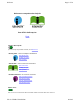
A Mounting bracket (2)
B Screw, M4-0.7x10mm pan head with internal tooth washer
C Back of tablet
A Foot
B Leg
C End caps (6)
D Lock washer (4)
E Caster (4)
F Screw, 1/4
-
20 x 2" flat head
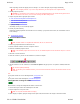
A Crossbar
B Screw, 1/4-20 x 2" flat head
C Leg assembly