USER'S AND INSTALLATION MANUAL 400 SERIES CC-1023ENG-10
1 400 SERIES 1. Quick Reference Guide 1.1. Master Unit 414A1/A2 1.2. Control Unit 422A1/A2 1.3. Control Unit 428A1+42991 1.4. Control Unit 428A1/A4 , 428A1+42992 2. 400 Series Overview 2.1. Introduction 2.2 .400 Series Components 2.3. Connecting Terminals 2.4. Basic Wiring Diagram 2.5. General Installation Notes 2.6. Programming Menus 2.7. Music channels 3. Central 3.1. Master Unit 414A1/A2 3.1.1. Operation 3.1.2. Program Menu 3.1.3. Settings Menu 3.1.4. Installation Menu 3.1.5. Technical Specifications 3.
2 MASTER UNIT 414A1/A2 414A1/A2 1.1. Quick Reference Guide Master Unit 414A1/A2 2. 400 Series Overview 2.1. Introduction 2.2. 400 Series Components 2.3. Connecting Terminals 2.4. Basic Wiring Diagram 2.5. General Installation Notes 2.6. Programming Menus 2.7. Music channels 3. Central 3.1. Master Unit 414A1/A2 3.1.1. Operation 3.1.2. Program Menu 3.1.3. Settings Menu 3.1.4. Installation Menu 3.1.5. Technical Specifications 3.2. Sound Input Unit 41591/92 3.2.1. Description 3.2.2.
CONTROL UNIT 428A1+42991 CONTROL UNIT 428A1+42992 428A1 42991 1.3. Quick Reference Guide Control Unit 428A1+42991 10 2. 400 Series Overview 2.1. Introduction 2.2. 400 Series Components 2.3. Connecting Terminals 2.4. Basic Wiring Diagram 2.5. General Installation Notes 2.6. Programming Menus 2.7. Music channels 4.1. Control Unit 428A1+42991 13 14 15 15 16 18 19 21 35 3 428A1 42992 1.4. Quick Reference Guide Control Unit 428A1+42992 12 2. 400 Series Overview 2.1. Introduction 2.2.
4 2 CONTROL UNIT 428A1/A4 428A1/A4 1.4. Quick Reference Guide Control Unit 428A1/A4 12 2. 400 Series Overview 13 2.1. Introduction 2.2. 400 Series Components 2.3. Connecting Terminals 2.4. Basic Wiring Diagram 2.5. General Installation Notes 2.6. Programming Menus 2.7. Music channels 4.2. Control Unit 428A1/A4 14 15 15 16 18 19 21 75 4.2.1. The first time... 4.2.2. Operating audio functions 4.2.3. Operating intercom calls functions 76 76 81 4.2.4. Program Menu 4.2.5. Installation Menu 88 92 4.
5 1.
6 1.1.
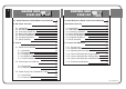
7 PROGRAM MENU CLOCKS 1 1 PRG QUICK ACCESS FUNCTIONS Time (Hour, minutes - Days, month, year) Auto power on (ON/OFF - Hour, minutes - Days of week) Auto power off (ON/OFF - Hour, minutes - Days of week) 3 def PRG 4 ghi PRG FM TUNER 6 mno PRG FM search sensitivity - Master Unit (4=max ...
8 1.2.
16 9 PROGRAM MENU CLOCKS 1 1 PRG 1 2 abc PRG 1 3 def PRG 1 4 ghi PRG 1 5 jkl PRG Alarm 1 (ON/OFF status - Hour, minutes - Days of week - Type - Volume) Alarm 2 (ON/OFF status - Hour, minutes - Days of week - Type - Volume) Auto Standby (ON/OFF status - Hour, minutes - Days of week) Sleep Time (Hour, minutes - Day, month, year) FM TUNER QUICK ACCESS FUNCTIONS 1 PRG 2 abc PRG 3 def PRG 4 ghi PRG 5 PRG jkl 6 mno PRG Alarm 1 status ON/OFF Alarm 2 status ON/OFF Autostandby status
10 1.3.
18 11 PROGRAM MENU CLOCKS 1 1 1 2 abc PRG PRG Hour, minutes Day, month, year ALARM 2 abc 1 PRG 2 abc 2 abc PRG 2 abc 3 def PRG 2 abc 4 ghi PRG ON/OFF Hour, minutes Type Volume FM TUNER QUICK ACCESS FUNCTIONS 1 PRG 4 ghi PRG 5 jkl PRG 7pqrs PRG 9 wxyz PRG 0C PRG Alarm status ON/OFF Do not disturb status ON/OFF Baby Monitor status ON/OFF General Standby for all zones Clear the baby monitor throughout the system Consult zone #, name and group (2") Activate Sleep FM Search sensiti
12 2 1.4.
13 2.
14 2. 400 Series Overview 2.1 Introduction The new 400 Series has arrived with optimal features and unparalleled quality. It showcases conspicuous and compact design especially tailored to the user. A superb ergonomic blending of the keypad and the screen icons make understanding its operation easy. It was designed for intuitive operation by the user through clear and easily accessible menus. The 400 Series was designed to provide a sound system for residential, commercial and business use.
15 2.3. Connecting Terminals 2.2. 400 Series Components Unit Control ref. 11295 11296 11295/96 power supply power type 14W reg.
16 2.4. Basic Wiring Diagram 194_4 POWER SUPPLY 194_5 POWER SUPPLY 16 ohm 16 ohm 16 ohm 16 ohm +- -+ +- -+ ON Right N F F’ COAX.ANT. M A 20 Az Ver Vio Na Bl Am Ro 10 M A 171 03 Az Ver Vio Na Bl Am Ro Az Ver Vio Na Bl Am Ro 93 06 05 04 60 50 40 30 20 10 7 92 91 4 2 CONTROL UNIT EIS CH FM PRG 93 06 05 04 60 50 40 30 20 10 7 92 91 4 2 171 03 Az Ver Am Na Ro Ma 171 05 220V EIS EIS 4 2 1 02 03 171 05 TELECONTROL SOCKET 220V. max 400W Right Az Ver Am Na Ro Ma COAX.ANT.
17 16 ohm 16 ohm 16 ohm 16 ohm +- -+ +- -+ Right Left COAX.ANT.
18 2.5. General Installation Notes £ A 400 Series system consists of two basic elements: a CENTRAL UNIT and several £ If the size of the installation requires the use of several CONTROL UNITS. The CENTRAL UNIT can be placed anywhere in the system and consists in one or more Power Supply Units a Master Unit 414A1/A2 and, optionally, several Sound Input Units 41591/92 Tuner of 414A2 Master Unit will be defaulted to channel #1 (terminal 10).
19 2.6. Program Menus KEYS TO THE SYMBOLS USED IN THIS MANUAL The appearance of this symbol over a key is a prompt to hold a key down for the time specified. 2.6.1. Three Access Levels The 414A1/A2 Master Units and the 422A1/A2 Control Units have three program menus of settings at different access levels. 5’’ In some cases it is necessary to hold down two keys simultaneously to PRG execute a specified operation. 2’’ Certain keys have a cursor function to scroll through different menus.
20 The following options are not available in 428A1, 428A4, 428A1+42992 models 428A1/A4 428A1 42992 Key Sequence 2.6.2. Programming Permission Pressing the 0 and 9 keys simultaneously blocks access to the programming and settings menus. To restore access to these menus, hold down the 0 and 9 keys. 2.6.3. Menu Navigation The program menus are structured in level and sub-level menus.. The following operations and keys in the menu will scroll the user between settings of the list of options.
21 2.7.
this page has been left intentionally in blank CC-1023ENG-10
23 3.
24 3.1. Master Unit 414A1/A2 3.1.1. Operation 3.1.1.A. Manual System Off/On Key Sequence Display Visual The first time power is fed to the Master Unit, the Master Unit begins operating in off mode. off The ON/OFF status of all system Control Units is regulated from the Master Unit. To switch on all the Control Units. press ON/OFF for the time specified. The Master Unit activates power supply to the system. The Control Units start up with the same settings playing as when last switched off.
25 3.1.1.C. Auto Switch Off This feature allows the user to program the Master Unit to automatically switch off the system at a specific time. That is, at the time and days of the week defined by the user, power will be shut off from all Control Units. It also alerts the Control Units prior to switching off so that the current settings are stored. Thus, the Control Units switch on with the same settings as at power off (ON/OFF status, audio levels, music channel).
26 3.1.1.F. Telecontrol function This feature allows the Master Unit to control the off/on status of the sound sources (apparatus) that supply the music channels. With this feature, the apparatus only switch on when a Control Unit activates a music channel, that is using the apparatus. The Control Units alert the Master Unit of a need for remote control, that is, that a Control Unit has switched to a music channel that requires remote control.
27 3.1.2. Program Menu 3.1.2.A. Time and Date The system’s time and date are shared by all connected units and can be programmed at any given unit. All other units will instantly be Key Sequences Display Visual updated accordingly.
28 3.1.2.C. Auto Power Off The option to program a time for the Master Unit to switch off the power supply at the time and days of the week programmed, switching off all the Control Units. Key Sequences Display Visual 3 def auto-POWER OFF 1 PRG Key Sequences Display Visual SA ON For example, auto power off at 17:50 every day of the week except Saturdays and Sundays.
29 3.1.2.E. Deleting FM Tuning Pre-sets -Master Unit (only 414A2) Key Sequences Display Visual The option to delete all the Master Unit FM tuning pre-sets. abc abc 2 To confirm the command to delete the data To initiate the process 2 2 abc PRG delete central fm memory off on PRG 3.1.2.G. ON/OFF dimmer Display window brightness for Master Unit ON/OFF status is programmed from these options.
30 3.1.3. Settings Menu 3.1.3.A. Languaje To select the language of all display text. Key Sequences 1 PRG To select a different language (for example, English) 3.1.3.B. Master Unit Name Allows you to personalize the Master Unit’s name (a maximum of 8 characters).
31 Key Sequence 3.1.3.F. Deleting Settings From The Master Unit Deletes all setting and programming data from the Master Unit, restoring the initial default settings. This option does not affect installation data (audio output, zone #, etc.). Activate delete process This operation does not start up the system’s clock-calendar. Initiate the process 3.1.4.A. Number Of Audio Channels Installed Defines the number of audio channels that exist in the system.
32 3.1.5.
33 3.2. Sound Input Unit 41591/92 3.2.1. Description For more than 2 music channels (up to a maximum of 6, including the tuner), additional sound input must be added (see 2.4. Basic Wiiring Diagram). They may be placed anywhere in the system, not necessarily adjacent to the Master Unit. 41591 model need no adjustment during installation. Its built-in compressor makes it unnecessary to have a potentiometer to regulate the signal input level. 41592 model has a potentiometer level manual adjustment 3.2.2.
34 3.3. Power Supply Unit 3.3.1. Description 3.3.2. Technical Specifications All sound systems have at least one primary power supply to constantly feed the Master Unit. If the size of the system warrants auxiliary power supplies, as many auxiliary power supplies as necessary may be added. The operation of the power supplies is fully automatic and directly controlled by Master Unit 414A1/A2 There are several power supply models compatible with the 400 Series (models 11204, 11295, 11296 and 11299).
35 4. Control Units 4.1.
36 4.1.1. The First Time... 422A1/A2 428A1 42991 The power supply for any Control Unit is controlled from the Master Unit 414A1/A2. See 3.1.1.A. Manual System Off/On Key Sequence The first time power is fed to a Control Unit it must be installed. The first step (required to continue) is to program its identification.
37 4.1.2. Operating audio functions 422A1/A2 428A1 42991 4.1.2.A. Manual Off/On Of Control Unit Key Sequence The Control Unit activates audio output with the previous settings with the press of a key. The display will be illuminated and the icon will be activated. Display Visual 10:56 Manual power off takes place in the same manner, the display darkens and the icon is disabled.
38 Key Sequence To access a channel directly, press the channel number followed by the CH key. For example, to select channel 3. To flip through the different channels, enter channel selection mode by pressing the CH key. 3 def CH Display Visual 03 CH In this mode the function of the +,- keys is channel selection. The channels scrolled through are the channels set up in each Control Unit only.
39 4.1.2.D. Operation Of The Control Unit’s Local FM Tuner (only: 422A2 & 428A1+42991) Key Sequence Display Some 400 Series Control Unit models are equipped with an internal FM tuner, set as music channel #0. Stations can be tuned in several different ways: 428A1 42991 frequency selection mode FM station tuned 8 tuv 9 wxyz 1 0 C FM frequency selection mode FM By directly keying in the station frequency, for example, to select the station 89.10 MHz.
40 Key Sequence Display Display 428A1 42991 422A2 To enter the frequency selection mode, press FM again. FM FM frequency selection mode FM station tuned automatic station search sensitivity level (1...4) frequency selection mode frequency frequency FM stereo frequency selection mode When pressed with a short key press, the +/- keys tune the frequency in intervals of 0.05 MHZ.
41 4.1.2.E. Store Station Pre-sets Into The Local FM Tuner (only 422A2 & 428A1+42991) Select the station frequency to be stored using any of the methods described in the previous point. If the reception quality is not satisfactory in stereo you can select forced mode, which is less demanding. To enter the store to memory In the Control Unit model 422A2 the mode, press the associated permission must be activated FM key. to execute this feature. See 4.1.5.F. Permission to Store/Delete FM Tuning Pre-sets.
42 4.1.2.H. Remote Use of the Master Unit FM Tuner If the system’s Master Unit has a tuner and the Control Unit is tuned to channel #1, access to the master tuner is possible. Unlike the case with the local tuner, stations can be tuned in only one way: by sequential scroll through the different pre-sets. The station tuned on the Master Unit tuner will be played throughout the system.
43 4.1.2.i. “Ideal” Settings Mode (only 422A1/A2) Each Control Unit has the feature to store “ideal” audio settings, which are pre-programmed settings that can be activated quickly and immediately. These settings consist of an audio channel and pre-set levels of volume, balance, bass, treble and loudness. Key Sequence Select the music channel to be designated as the “ideal” settings mode.
44 4.1.2.K. General Standby All Control Units have the ability to make any unit connected to the system go into standby mode ( music off). Key Sequence For activate/clear use the quick function 7pqrs PRG 4 ghi 1 Display Visual standby The associated permission must be activated to execute this feature (see 4.1.5.G or 4.1.8.J) 4.1.2.L. Sleep The sleep function shuts the Control Unit off after a predefined time entered at power on. The user can program the time.
45 4.1.2.M. Alarms The 400 series Control Units are equipped with two alarms that can be individually programmed and can operate in two different modes: “Music” mode alarm: \ Operates only when the Control Unit is off. \ At the time and days programmed, the Control Unit switches on with the last music channel played.
46 4.1.3. Operating intercom calls functions 422A1/A2 428A1 42991 4.1.3.A. Calls To An Individual Zone An intercom call to an individual zone is an intercommunication call between two zones in half-duplex setup with hands-free response. A Control Unit is identified by its zone identification number (see 4.1.6.A or 4.1.8.A) and a name (see 4.1.5.B or 4.1.7.M).
47 Changing the intercom call receipt volume 1 2 3 4 5 6 7 FM 1 Initiating a conversation Either of the two parties may initiate a conversation at any time by pressing the key. Ending an intercom call operation 2 The volume of the intercom call received is the volume programmed in sections 4.1.4.H or 4.1.7.G Receive Intercom Calls Volume. To adjust the volume, use the +/- keys while the intercom call is being received (when the intercom call is over, the volume setting will be stored in memory).
48 Select the group that will receive the intercom call Transmit the intercom call On the numeric keypad, key in the group number you wish to call, followed by the group key (to delete an entry, pres the 0 key for ½”). For example, to call group 4... To talk, press the talk key and hold it down throughout the transmission. If the operation could not be initiated for any reason, a message will appear on the display.
49 4.1.3.C. Communication with the entryphone intercom Systems with one or several interface units for one or several entryphone intercom units offer the ability to have a speak/listen type conversation with the person at the exterior door from any of the system's control units, including the option of letting the person in the door. Each entryphone intercom is identified by a zone address number, a name and a specific buzz tone. Buzz tones are programmable from the interface unit (ref. 43494) itself.
50 4.1.3.D. Electronic Baby Monitor The Baby Monitor is an intercom call operation to an individual identification which is automatically initiated when sound is detected by a Control Unit. It is designed to monitor someone who cannot access the keypad to transmit a voice message (a child, a disabled person, an older person...).It is programmed at the transmitting Control Unit (zone to be monitored). There can be more than one Baby Monitor function operating in a system.
51 4.1.3.E. Do Not Disturb Function It is possible to activate the “Do not disturb” function on a Control Unit to disallow the receipt of any kind of calls. When this function is activated, the talk/auto-response process becomes talk only as it is no longer possible to receive intercom calls (see 4.1.3.H. Intercom Call Permissions) Key Sequence Display Visual 4 ghi PRG NOTIF x 6 mno PRG 1 john 4.1.3.F.
52 4.1.3.H. Intercom Calls Permissions By default, the manufacturer leaves all intercom calls permissions activated on Control Units. To limit any intercom call operations, access the specific blocks according to the following table. (The options are accessible from the program, settings and installation menus).
53 4.1.4. Control Unit : Program Menu 422A1/A2 4.1.4.A. Alarm 1 & 2 Key Sequences Each Control Unit is equipped with two programmable alarms with two operation modes, as described in section 4.1.2.M. Alarms 1 1 1 Alarm 1 alarm1 Enter to program the days of the week alarm will be set. jkl ON/OFF 5 jkl off Scroll through days. on Change. Store. PRG jkl … SA ON 2 abc Scroll through days. Scroll to next program setting in alarm mode. Enter to program time.
54 del mando Key Sequences Key Sequences Display Visual 8 tuv Volume Scroll to next program setting in alarm mode. 5 For example, auto standby at 23:45 every weekday except Saturday and Sunday. PRG SU ON SU OFF dAYS Key Sequences Display Visual PRG 2 abc Key Sequences 1 3 def 5 jkl 5 jkl 2 abc off on ON/OFF hh-mm 8 tuv 2 abc 3 def jkl 4 ghi PRG Display Visual autostandby ON/OFF PRG PRG 5 jkl ... vol 86 Store.
55 4.1.4.F. Deleting FM Tuning Pre-sets (only 422A2) 4.1.4.E. FM Search Sensitivity (only 422A2) The option to adjust the automatic station search sensitivity for the Control Unit’s internal FM tuner. To adjust the new sensitivity; 4=max, 1=min. Key Sequences 2 abc 1 PRG 2 abc Display Visual fm sensitivity sens 4 sens 2 PRG Store. The option to delete all the Control Unit’s internal FM tuner pre-sets. Key Sequences 2 abc To confirm the command to delete the data.
56 4.1.4.H. Receive Intercom Calls Volume To adjust the volume of the intercom calls received at this Control Unit. Key Sequences 3 def PRG 1 Adjust by raising or lowering the volume. Or adjust by directly keying in volume level. Store. 7pqrs 0C Display Visual INTERCOM CALLS VOLUME vol 50 vol 60 vol 70 4.1.4.i. Permission To Receive Individual, Group Or General Intercom Calls Key Sequences It is possible to select the type of call received by a Control Unit.
57 4.1.4.J. Permission To Transmit General Intercom Calls Transmitting “general intercom calls” can be cancelled in a Control Unit. Key Sequences 4 ghi 1 To cancel permission. 2 abc Store. PRG PRG Display Visual General intercom calls on off Permission to transmit intercom calls must be activated for this option to be available (see 4.1.6.E) 4.1.4.K. Baby Monitor See 4.1.3.D. Baby Monitor function. To program the Baby Monitor settings.
58 Key Sequences Scroll to the next programmable Baby Monitor setting. Enter to program the silence time. 8 tuv 5 Display Visual Time 4 sec Key Sequences 4.1.4.L. Auto-response See 4.1.3.A. Intercom call to an individual zone. To program autoresponse settings. 8 sec Store. PRG Scroll to the next programmable Baby Monitor setting. 8 tuv jkl Address Adr 23 jkl 5 jkl auto-respONSE ON/OFF 2 abc Store. PRG off on ON/OFF Scroll to the next programmable auto-response setting.
59 Key Sequences Display Visual 8 tuv tiME Scroll to the next programmable autoresponse setting Scroll to the next programmable Baby Monitor setting 5 Control Unit’s display window brightness for ON/OFF functions can be programmed from this seg 4 jkl Key Sequences 5 jkl 2 abc PRG 5 jkl 3 def PRG Display Visual light off o Light on Lt 5 Lt 8 Adjust level Change the setting seg 8 Store Store PRG PRG End and exit 4.1.4.O.
60 4.1.5. Control Unit : Settings Menu 422A1/A2 4.1.5.A. Language Key Sequences Selects the language of all display text. 1 PRG To select a different language (for example, English). 4.1.5.B. Control Unit Name Key Sequences 2 abc PRG 7pqrs 7pqrs NAME zona 2’’ 7pqrs 7pqrs 2 abc 6 mno 5 jkl 6 mno 6 mno Store Display Visual zona 5 Key in the new name using the alphanumeric keypad. englsh PRG Allows you to personalize the Control Unit’s name (a maximum of 8 characters).
61 4.1.5.E. Access To Master Unit FM Tuner 4.1.5.G. Permission To Access General Standby Controls Master Unit tuner access to change the station from the Control Unit itself. By disallowing access, the station on the Master Unit tuner cannot be changed from the Control Unit itself (it can always be changed by directly accessing it through the Master Unit keypad). Disallows Control Unit access to the option to switch off the whole system. See 4.1.2.H.
62 Key Sequence 4.1.5.i. Deleting Control Unit Settings Deletes all setting and programming data from the Control Unit, restoring the initial default settings. This option does not affect installation data. 4.1.6 Control Unit 9 wxyz PRG Activate delete process. 2 abc Initiate the process. PRG 2’’ Display Visual DELETE configuration off LOADING DATA : Installation Menu 422A1/A2 4.1.6.A.
3. Instalación 63 del mando 4.1.6.C. Mono/Stereo Defines whether the Control Unit’s audio output (terminals 04, 05, 06) is connected in mono or stereo mode. In a Control Unit in stereo, outputs 05 and 06 respond to the left and right channels. In a Control Unit in mono, both outputs are identical and can therefore be used interchangeably. To change the output setting to mono Key Sequence 3 def PRG See 4.1.3.H. Control Unit Operation: Intercom Call Permissions See 4.1.3.H.
64 Key Sequence 4.1.6.G. Last Channel Number Accessible From The Control Unit The number of music channels installed is defined in the Master Unit. The Control Units have the same setting by default in order to recognize the last channel installed. Therefore the Control Unit will initially have access to the channels defined in the Master Unit. To modify a Control Unit’s access to more or less channels than those defined in the Master Unit, use that option of the installation menu.
65 4.1.7. Control Unit : Program Menu 428A1 42991 4.1.7.A. Date and Time The system’s time and date is shared by all connected units and can be programmed at any unit whatsoever. All other units will instantly update the change. Key Sequences Display Visual Access to program menu Enter to program the time PRG 5 jkl ON/OFF TIME 8 tuv hh-mm HH-MM Enter to program time. 5 00-00 4.1.7.B.
66 4.1.7.C. FM Search Sensitivity The option to adjust the automatic station search sensitivity for the Control Unit’s internal FM tuner. Key Sequences Enter code 3 def To adjust the new sensitivity; 4=max, 1=min. 1 2 Store PRG abc Display Visual fm SENSITIVITY sens 4 PRG The option to delete all the Control Unit’s internal FM tuner presets. Key Sequences Display Visual 3 def 2 abc PRG To confirm the command to delete the data. 2 abc To initiate the process.
67 4.1.7.G. Receive Intercom Calls Volume To adjust the volume of the intercom calls received at this Control Unit. Key Sequences 4 ghi 2 abc PRG Adjust by raising or lowering the volume. Or adjust by directly keying in volume level. 7pqrs Store Display Visual Intercom calls volume vol 50 vol 60 vol 70 0C Permission to receive intercom calls must be activated for this option to be available (see 4.1.8.G. Permission to Receive Intercom Calls).
68 Key Sequences 4.1.7.i. Baby Monitor See 4.1.3.D. Baby Monitor function. To program its settings... Access to program menu Scroll forward until this option Enter to program Enter to activate/desativate the baby moniitor function (also available as a quick access function, see 2.2) Key Sequences Display Visual PRG PROG 8 tuv 5 5 jkl jkl baby monitor ON/OFF off Store PRG Scroll to the next programmable Baby Monitor setting. 8 tuv Change the value Store PRG oN Store.
69 4.1.7.J. Language Selects the language of all display text.
70 4.1.8. Control Unit : Installation Menu 428A1 42991 Key Sequence 4.1.8.A. Zone Identification A Control Unit is identified in the system by a zone identification number, a group identification number (optional) and a name (optional). The zone identification number must be a number between 1 and 250 and be different for each Control Unit installed. 1 For example, to define a zone identification as number 64 4.1.8.B. Group Group identification numbers must be between 1 and 250.
71 4.1.8.E. Last Channel Number Accessible From The Control Unit The number of music channels installed is defined in the Master Unit. The Control Units have the same setting by default in order to recognize the last channel installed. Therefore the Control Unit will initially have access to the channels defined in the Master Unit. To modify a Control Unit’s access to more or less channels than those defined in the Master Unit, use that option of the installation menu.
72 4.1.8.i. Access To Master Unit FM Tuner Controls Master Unit tuner access to change the station from the Control Unit itself. By disallowing access, the station on the Master Unit tuner cannot be changed from the Control Unit itself (it can always be changed by directly accessing it through the Master Unit keypad). Key Sequences Display Visual See 4.1.2.H. Operation of 9 wxyz PRG 2’’ Access to central fm Master Unit FM ON Tuner Disallow access. 2 abc Store PRG off 4.1.8.K.
73 4.1.8.M. Deleting Control Unit Settings (manufacturer reset) Deletes all settings and programming data from the Control Unit, restoring manufacturer default settings. Key Sequences 1 3 def PRG To activate delete process 2 abc To initiate the process PRG To reset the manufacturer's settings without having to immediately go to the Installation Menu, press the 0 and 2 keys for 5”. 0C 2 abc 2’’ 4.1.8.N.
74 4.1.9. Technical Specifications 422A1/A2 428A1 42991 Connecting terminals mod.
75 4. Control Units 4.2.
76 4.2. Control Units & 428A1/A4 428A1 42992 4.2.1. The First Time... The first time power is fed to a Control Unit it must be installed. The first step (required to continue) is to program its identification. A Control Unit is identified by: ) an individual zone identification (installation menu) ) a group identification (installation menu) The power supply for any Control Unit is controlled from the Master Unit 414A1/A2. See 3.1.1.A.
77 4.2.2.B. The m Key: How to Use the Functions to Adjust the Music in Control Unit The audio inputs of each 428A1 Control Unit can handle up to 2 music channel connections. Channel #1 will synch up to the Master Unit’s FM tuner, which can be operated remotely from the Control Unit itself. The sound input through the jack on the face of the Control Unit synchs up to channel #CD. In total, each Control Unit can have up to 3 music channels numbered as shown in chapter 1.
78 Key Sequence The store/clear of FM tuner memory settings on the master unit FM tuner can only be programmed at the 414A2 master unit itself. See Setting Menu: Access to Master Unit FM Tuner (4.2.5.i) Once the music station (or FM tuner station on the master unit, in its case) is selected, you can press the m key to return to the volume adjustment setting. m m Pressing the m key several times switches you between the adjustment modes for base, treble, loudness and balance.
79 The default function for the +/- keys when the Control Unit is on is to adjust the control unit ON volume. A few seconds after the last key entry the Control Unit will return to its default function of volume adjustment. WITH THE CONTROL UNIT ON (the icon activated), the m key allows you to scroll through the various functions that adjust the music. In this mode the +,- keys function to select the station.
80 4.2.2.D. Operation & Store Station Pre-sets of the Control Unit’s Local FM Tuner The Program Menu has the option to search and automatically store stations at the optimal reception level (see 4.2.4.B) 428A4 428A1 42992 control unit ON Press m key for channel selection. Select Local FM tuner with +/- keys. To enter the memory pre-set selection mode, press m again. The display will show the frequency of the current station.
81 4.2.2.F. Alarm The 428A1 Control Unit is equipped with an alarm that can be programmed and can operate in two different modes: “Music” mode alarm: \ Operates only when the Control Unit is off. \ At the time programmed, the Control Unit switches on with the last music channel played. \ The volume is programmable See Program Menu (4.2.4.A.) “Beep” mode alarm: \ Operates whether the Control Unit is off or on \ At the time programmed, the Control Unit switches on and a specific beep signal is activated.
82 4.2.3.B. Calls To An Individual Zone An intercom call to an individual zone is an intercommunication call between two zones in half-duplex setup with hands-free response. A Control Unit is identified by its zone identification number (see 4.2.5.A.
83 Changing the intercom call receipt volume m ZONe 01 ZONe 06 Initiating a conversation The volume of the intercom call received is the volume programmed in sections 4.2.4.D. Receive Intercom Calls Volume. To adjust the volume, use the +/- keys while the intercom call is being received (when the intercom call is over, the volume setting will be stored in memory). It is possible to totally or partially block the call/auto-response process. See 4.2.3.F.”Do not disturb” function and 4.2.3.H.
84 Transmit the intercom call m key and hold it down To talk, press the talk throughout the transmission. If the operation could not be initiated for any reason, a message will appear on the display. The intercom call will be transmitted while the key is held down (the maximum duration is 1'). The name of the zone transmitting the intercom call appears on the display of the Control Unit receiving the message.
85 Buzz tones are programmable from the interface unit (ref. 43494) itself. It is possible to program the zone number and name without the assistance of the installer and can be changed with the PC software by using the PC interface (ref. 43491). For all purposes (permissions, level programming, etc.) communication operations with the entryphone intercom behave the same way as communication between zones, in this case the entryphone intercom interface being one of the zones.
86 If the Baby Monitor function has been activated successfully (that is, the transmitting Control Unit has the required permissions and the receiving unit is hooked up and can receive intercom calls) the icon will appear flashing. The Control Unit accepts any form of operation: on, off, ... When sound is detected in the room the Control Unit transmits an intercom call without any key having been pressed. The intercom call will last as long as the silence time programmed in the Baby Monitor settings.
87 4.2.3.H. Intercom Calls Permissions By default, the manufacturer leaves all intercom calls permissions activated on Control Units. To limit any intercom call operations, access the specific blocks according to the following table. (The options are accessible from the program and installation menus).
88 4.2.4. Control Units & 428A1/A4 : Program Menu 428A1 42992 4.2.4.A. Alarm Each Control Unit is equipped with one programmable alarm with two operation modes, as described in section 4.2.2.F. Control Unit Operation: Alarms Key Sequences Enter to program alarm clock activate/clear PROG m ALARM ON/OFF m 2’’ Store hh-mm m Store 2’’ 00-00 06-50 Set the time Enter program to select alarm sound.
89 4.2.4.B. FM tuner The option to adjust the automatic station search sensitivity for the Control Unit’s internal FM tuner. Not available on 428A1 Control Unit 428A1 Key Sequences Display Visual control unit OFF m Enter to program menu and scroll to programming “FM search sensitivity” ... m fm SENSITIVITY 2’’ To adjust the new sensitivity; 4=max, 1=min. Press to store The option to delete all the Control Unit’s internal FM tuner presets.
90 4.2.4.C. “Do Not Disturb” Function It is possible to activate the “do not disturb” function on a Control Unit to disallow the receipt of any Key Sequences Display Visual kind of calls (see 4.2.3.F.) Enter to program menu control unit OFF Scroll to programming “do not disturb” function Enter to activate/desactivate this function PROG DO NOT DISTURB ON/OFF m ... m 2’’ on Change Store 4.2.4.D.
91 4.2.4.F. Baby Monitor Enter to program control unit OFF menu. Scroll to programming baby monitor options. Press the m key to enter to activate/clear the baby monitor Key Sequences m m ... Change Store Store address m 2’’ control Enter to program unit OFF menu Scroll to programming the language and select a different language (for example, English) adr 03 m PROG ... LANGUAGE m 2’’ ESPAÑOL english Change m 4.2.4.H.
92 4.2.5. Control Units & 428A1/A4 : Installation Menu 428A1 42992 4.2.5.A. Zone Identification control unit OFF A Control Unit is identified in the system by a zone identification number, a group identification number (optional) and a name (optional). The zone identification number must be a number between 1 and 250 and be different for each Control Unit installed. It is not necessary for the numbers to be consecutive. Key Sequence 2’’ m m To program the zone number, enter the installation menu.
93 Key Sequence Display Visual m STEREO Enter to change the setting between mono and stereo values 2’’ MONO Change 4.2.5.D. Audio Output Defines the impedance connected to the Control Unit’s audio output (terminals 04, 05, 06) from the following options: 16 ohm passive loudspeaker 8 ohm passive loudspeaker amplifier line Store control unit OFF m 2’’ m Entrar en el menú de instalación y avanzar hasta llegar a esta opción. ...
94 4.2.5.F. Permission To Transmit Intercom Calls The “transmit intercom calls” option may be permanently disabled from a control unit OFF Control Unit without affecting its ability to receive intercom calls. Note that Control Units with “transmit intercom calls” switched off cannot use the autoresponse feature. Enter the installation menu and scroll to that option. Press the m key to enter and change the value See 4.2.3.H. Intercom Call Permissions Key Sequence Display Visual INSTAL 2’’ m ...
95 4.2.5.i. Access To Master Unit FM Tuner control unit OFF Controls Master Unit tuner access to change the station from the Control Unit itself. By disallowing access, the station on the Master Unit tuner cannot be changed from the Control Unit itself (it can always be changed by directly accessing it through the Master Unit keypad). Enter the installation menu and scroll to that option. Press the m key to enter and change the value See 4.2.2.B. Operation of Master Unit FM Tuner 4.2.5.K.
96 4.2.5.L. Deleting Control Unit Installation (Manufacturer Reset) Deletes all settings and programming data from the Control Unit, restoring manufacturer default settings. Key Sequence control unit OFF Enter the installation menu and scroll to that option. Press the m key to enter and change the value Once the Control Unit is switched on, the manufacturer default settings are activated. This means that its zone identification must be redefined since it is required for the unit to operate. See 4.2.5.A.
4.2.6. Control unit unit 97 : Operation using the remote control 428A1 42992 Further to the additional features it offers (FM tuner and 4 music channel inputs), when the supplementary 42992 unit is installed with unit 428A1, it allows the user to operate audio features and intercom calls with the same remote control unit, ref. 42791.
98 94 4.2.7.
Electrónica Integral de Sonido S.A. reserves the right to make changes without prior notice. Electrónica Integral de Sonido S.A. is not responsible for errors or omissions in this manual. CENTRAL Polígono Malpica Calle F Oeste Grupo Gregorio Quejido, 87-88 50016 Zaragoza (SPAIN) Tel.: 34 976 465 550 Fax: 34 976 465 559 comercial@eissound.com www.eissound.