User’s Manual Color LCD Monitor
English SAFETY SYMBOLS This manual uses the safety symbols below. They denote critical information. Please read them carefully. WARNING Failure to abide by the information in a WARNING may result in serious injury and can be life threatening. CAUTION Failure to abide by the information in a CAUTION may result in moderate injury and/or property or product damage. Indicates a prohibited action. Indicates to ground for safety. Copyright© 2001 by EIZO NANAO CORPORATION. All rights reserved.
English TABLE OF CONTENTS PRECAUTIONS ................................................................................... 4 1. INTRODUCTION ..................................................................................... 9 1-1. Features....................................................................................................... 9 1-2. Package Contents ........................................................................................ 9 1-3. Controls & Connectors ........................
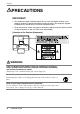
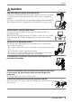
English PRECAUTIONS IMPORTANT! • This product has been adjusted specifically for use in the region to which it was originally shipped. If operated outside the region to which it was originally shipped, the product may not perform as stated in the specifications. • To ensure personal safety and proper maintenance, please read this section and the caution statements on the unit (refer to the figure below).
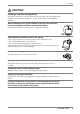
English WARNING Keep small objects or liquids away from the unit. Small objects accidentally falling through the ventilation slots into the cabinet or spillage into the cabinet may result in fire, electric shock, or equipment damage. If an object or liquid falls/spills into the cabinet, unplug the unit immediately. Have the unit checked by a qualified service engineer before using it again. Place the unit on a strong, stable surface.
English WARNING The equipment must be connected to a grounded main outlet. Not doing so may cause in fire or electric shock. Use the correct voltage. * Do not overload your power circuit, as this may result in fire or electric shock. * The unit is designed for use with a specific voltage only. Connection to another voltage than specified in this User’s Manual may cause fire, electric shock, or other damage. * Do not overload your power circuit, as this may result in fire or electric shock.
English CAUTION Handle with care when carrying the unit. Disconnect the power cord and cables when moving the unit. Moving the unit with the cord attached is dangerous. It may result in injury or equipment damage. When handling the unit, grip the bottom of the unit firmly with both hands ensuring the panel faces outward before lifting. Dropping the unit may result in injury or equipment damage. OK SIG. AUTO ENT. Do not block the ventilation slots on the cabinet.
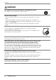
English LCD Panel The screen may have defective pixels. These pixels may appear as slightly light or dark area on the screen. This is due to the characteristics of the panel itself, and not the product. The backlight of the LCD panel has a fixed life span. When the screen becomes dark or begins to flicker, please contact your dealer. Do not press on the panel or edge of the frame strongly, as this will result in damage to the screen.
English 1. INTRODUCTION Thank you very much for choosing an EIZO Color Monitor. 1-1. Features • Dual inputs compliant • DVI (p.34) Digital input (TMDS (p.35)) compliant. • Horizontal scanning frequency: 24.8 - 80 kHz (Digital input: 31.5 - 64 kHz) Vertical scanning frequency: 55 - 75 Hz Vertical (Digital: 60 Hz (VGA text: 70 Hz)) Resolution: 1280 dots x 1024 lines • Auto Adjustment compliant • ColorManagement function incorporated • Support to sRGB (p.35) standard • Built-in speaker system 1-2.
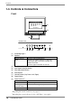
English 1-3. Controls & Connectors Front (1) (2) SIG. AUTO ENT. (3) Control Panel SIG. AUTO ENT. (4) (5) (6) (1) (2) (3) (4) (5) (6) (7) (8) (9) *1 *2 10 (7) (8) (9) ScreenManager *1 Speaker Volume Control Press the right and left buttons. Mute Press the up or down button for a while after pressing the right or left button to display the volume control bar. Press the right or left button to mute off.
English Rear (15) POWER INPUT DVI D-SUB (14) (16) Bottom (10) (10) (11) (12) (13) (14) (15) (16) *3 *4 (11) (12) (13) Power Connector External line in (stereo mini-jack) DVI-D Input Connector (Signal 1) D-Sub mini 15 pin Input Connector (Signal 2) 3 Security Lock Slot* *4 4 Holes for Mounting an Arm-Stand *4 Stand (Detachable) Allows for connection of a security cable. This lock supports Kensington’s MicroSaver security system.
English 2. CABLE CONNECTION 2-1. Before connecting Before connecting your monitor to the PC, change the display screen settings (resolution (p.34) and frequency) in accordance with the charts below. NOTE • The lower display modes like 640x 480, automatically enlarge to the maximum display mode (1280 x 1024), and some lines of the characters may become fuzzy. In this case, use function (p.22) to make the lines clear.
English 2-2. Connecting the signal cable NOTE • Be sure that the power switches of both the PC and the monitor are OFF. 1. Plug the signal cable into the connector at the rear of the monitor and the other end of the cable into the video connector on the PC. After connecting, secure the connection with the screw-in fasteners.
English 2. Plug the power cord into the power connector on the rear of the monitor. Then, plug the other end of the cord into a power outlet. WARNING Use the enclosed power cord and connect to the standard power outlet of your country. Be sure to remain within the rated voltage of the power cord. Not doing so may cause in fire or electric shock. The equipment must be connected to a grounded main outlet. Not doing so may cause in fire or electric shock. 3.
English 2-3. Sound Connections NOTE • Always switch the monitor and audio devices or computers off whenever connecting or disconnecting any audio devices (computer or CD player) to the monitor. • Use the enclosed stereo mini-jack cable for connecting audio devices or computers to the monitor. 1. Connect the stereo mini-jack cable to the external line in of the monitor. 2. Connect the other side of stereo mini-jack cable to the line out of audio devices.
English 3. ScreenManager 3-1. How to use the ScreenManager Control Buttons Left, Down, Up, Right SIG. AUTO SIG. ENT. AUTO ENT. Auto Adjustment button Enter button 1. Entering the ScreenManager Push the Enter button once to display the main menu of the ScreenManager. [Main Menu ] 2. Making Adjustments and Settings (1) Select the desired sub menu icon using the Control buttons and push the Enter button. The sub menu appears.
English NOTE • Double clicking the Enter button at any time also exits the ScreenManager menu. 3-2. Adjustments and Settings The following table shows all the ScreenManager’s adjustment and setting menus. “*” indicates adjustments of analog input only and “**” indicates digital input only. Main menu Screen Sub menu Reference Clock * Phase * Position * 4-1. Screen Adjustment (p.20) Smoothing Brightness /Contrast ColorManagement Range Adjustment * 4-2. Color Adjustment (p.
English 3-3. Useful Functions Adjustment Lock Use the “Adjustment Lock” function to prevent any accidental changes. Locked function • Auto adjustment button adjustments and settings in the ScreenManager. Unlocked function • Adjustment of contrast and brightness by the control buttons. • Sound control by the control buttons. • Input signal selection button • To lock Switch off the monitor’s power by the power switch. Press on the Auto adjustment button while switching on the monitor’s power.
English EIZO Logo disappearing function When switching on the power button on the front panel, the EIZO logo is displyed for a while. If you desire to display or undisplay this logo, use this function. (Default is logo appearing.) • To undisplay Switch off the monitor’s power by the power switch, then hold down the Enter button once again and turn the power back on. • To display Switch off the monitor’s power by the power switch, then hold down the Enter button once again and turn the power back on.
English 4. ADJUSTMENT The monitor displays the digital input image correctly based on its pre-setting data. Adjust the contrast and brightness (p.23). 4-1. Screen Adjustment Screen adjustments for the LCD monitor should be used in suppressing screen flickering and also for adjusting the screen to its proper position. There is only one correct position for each display mode. It is also recommended to use the ScreenManager function when first installing the display or whenever changing the system.
English 3. Adjust by using menu in the ScreenManager. (1) Vertical bars appear on the screen Use the (p.34) adjustment. → Select the and eliminate the vertical bars by using the right and left of the control buttons. Do not continuously press the control buttons, as the adjustment value will change quickly and make it difficult to locate the most suitable adjustment point. If the horizontal flickering, blur or bars appear, proceed to adjustment as follows.
English 4. To adjust the output signal range (Dynamic Range) of the signal. → Use the (p.35)of menu. This controls the level of output signal range to display the whole color gradation (256 colors). [Procedure 1] Push the Auto adjustment button on the front panel while displaying the menu to automatically adjust the range. The screen blanks for a moment, and adjusts the color range to display the whole color gradation of the current output signal.
English 6. To set the Contrast of the screen. → Use the adjustment. This controls the brightness for the each color (red, blue and green) at the same time. Select and adjust by using the right and left buttons. NOTE • Percentage except 100 % may cause undisplayable color tone. • During selecting the of , contrast cannot be adjusted. 7. To Set the Brightness of the screen. → Use the adjustment.
English 4-2. Color Adjustment The menu in the ScreenManager enables to change the color of the screen. By using the , the adjustment mode can be selected from (to adjust the color settings according to your preference) and mode. In the analog input, perform the “Range Adjustment” (p.22) before making the color adjustments. NOTE • Allow the LCD monitor to stabilize for at least 20 minutes before making image adjustments.
English NOTE • The “Hue” adjustment may cause undisplayable color tone. To change each color (red, green and blue). → Use the (p.34)adjustment. By adjusting the red, green and blue color tones for each mode, custom colors can be defined. The 100 % indicates unadjusted condition. Display a white or gray background image and adjust the . NOTE • The values shown in the percentage are available only as a reference tool.
English Digital input This monitor complies with the DVI DMPM (p.34). [Procedure] (1) Set the PC’s power saving settings. (2) Select “DVI DMPM” from the “PowerManager” menu. [Power saving system] *1 PC Monitor LED Operation Power saving Operation Power saving Off mode Power saving*1 Blue Yellow Flashing yellow (2 times for each) Power saving through the PC’s off mode is only supported when “Manual” is selected on the ScreenManager’s .
English 5. ATTACHING AN ARM STAND The LCD monitor can be used with an arm stand by removing the tilt stand and attaching the arm stand to the LCD monitor. NOTE • Use an arm stand that satisfies the followings. - When using the LCD monitor with an arm stand, the arm stand must be VESA approved : * Use an arm stand with a 75 mm x 75 mm hole spacing on the arm mounting pad. * Weight: Use an arm stand that is able to support an object weighting 8.0 kg.
English 6. TROUBLESHOOTING If a problem persists even after applying the suggested remedies, contact an EIZO dealer. • No picture problems : See No.1 ~ No.2 • Imaging problems : See No.3 ~ No.11 • Other problems : See No.12 ~ No.14 Problems 1. No picture • Indicator status: Off • Indicator status: Blue • Indicator status: Yellow • Indicator status: Flashing yellow (2 times for each) 2. ! Check that the power cord is correctly connected.
English Problems Points to check with possible solutions 3. Display position is incorrect. ! Adjust the image position using the (p.21) ! The two display modes, VGA 720 x 400 (70 Hz) and 320 x 200 (70 Hz), have the same signal timings. Using this adjustment selects the appropriate display mode. (This function effects only when the resolution is VGA 720 x 400 (70 Hz) or 320 x 200 (70 Hz).
English Problems Points to check with possible solutions 10. Fingerprints remain on the screen. ! Leaving the screen white may solve the problem. 11. The cannot be selected. ! is disabled when the screen is displayed in the 1280 x 1024. 12. The Enter button does not operate. ! The adjustment lock is probably on. To unlock: switch the LCD monitor off. Then, while pressing the Auto adjustment button switch, the power on. (p.18) 13. The Auto adjustment button does not operate.
English 7. CLEANING Periodic cleaning is recommended to keep the monitor looking new and to prolong its operation lifetime. NOTE • Never use thinner, benzene, alcohol (ethanol, methanol, or isopropyl alcohol), abrasive cleaners, or other strong solvents, as these may cause damage to the cabinet or LCD panel. Cabinet To remove stains, wipe the cabinet with a soft, lightly moistened cloth using a mild detergent. Do not spray wax or cleaner directly into the cabinet.
English 8. SPECIFICATIONS LCD Panel 41 cm (16.0 inch), TFT color LCD panel with Anti-Glare Hard Coating Viewing Angle: H: 160°, V: 130° (at contrast ratio 1:5) Dot Pitch 0.248 mm Horizontal Scan Frequency 24.8 kHz - 80 kHz (Automatic) (Digital): 31.5~64 kHz Vertical Scan Frequency 55 Hz ~75 Hz (Automatic) (Digital): 60Hz, (VGA Text : 70Hz) Resolution 1280 dots x 1024 lines Dot Clock (Max.) 135 MHz (Digital: 108 MHz) Display Colors 16 million colors (max.) Display Area 317 mm (H) ×253 mm (V) (12.
English Default settings Analog input Digital input Contrast 100% Brightness 100% Smoothing On Color Management Custom mode / Off (Normal white) PowerManager VESA DPMS Input Signal Auto Off Timer Disable Language English DVI DMPM Dimensions Unit mm (inches) 54(2.1) 34.8(1.37) 65(2.6) 1.0(0.04) 398(15.7) 247.8(9.76) 255.8(10.07) 370(14.5) 319.2(12.57) 22.5 (0.89) 1.0(0.04) 155(6.1) 157(6.
English 9. GLOSSARY Afterimage The Afterimage is particular to LCD monitors when the monitor screen is left on for a long period without use. The “Afterimage” can be removed gradually by changing the displayed image. Clock With the analog input signal display, the analog signal is converted to a digital signal by the LCD circuitry. To convert the signal correctly, the LCD monitor needs to produce the same number clock pulse as the dot clock of the graphics system.
English Phase The phase adjustment decides the sampling timing point for converting the analog input signal to a digital signal. Adjusting the phase after the clock adjustment will produce a clear screen. Range Adjustment The Range Adjustment controls the level of output signal range to display the whole color gradation. Resolution The LCD panel consists of a fixed number of pixel elements which are illuminated to form the screen image.
English MEMO 36 MEMO
APPENDIX/ANHANG/ANNEXE Preset Timing Chart for Analog input Timing-Übersichten für Analog Eingang Synchronisation des Signaux pour Analog numerique Based on the signal diagram shown below 20 factory presets have been registered in the monitor's microprocessor. Der integrierte Mikroprozessor des Monitors unterstützt 20 werkseitige Standardeinstellungen (siehe hierzu die nachfolgenden Diagramme).
Mode Dot Clock MHz Sync Polarity H V Frequencies H kHz V Hz A: Front Porch H µs/Dot V ms/Line B: Sync Period H µs/ Dot V ms/ Line VGA 640 × 480 25.2 Nega. Nega. 31.47 59.94 0.636/ 16 0.318/ 10 3.813/ 96 0.054/ 2 VGA 720 × 400 28.3 Nega. Posi. 31.47 70.09 0.636/ 18 0.381/ 12 3.813/ 108 0.064/ 2 Macintosh 640 × 480 30.2 Posi. Posi. 35.00 66.67 2.116/ 64 0.086/ 3 2.116/ 64 0.086/ 3 Macintosh 832 × 624 57.3 Posi. Posi. 49.73 74.55 0.559/ 32 0.020/ 1 1.117/ 64 0.
C: Back Porch D: Blanking Period E: Display Period F: Total Cycle H µs/ Dot V ms/ Line H µs/ Dot V ms/ Line H µs/ Dot V ms/ Line H µs/ Dot V ms/ Line 1.907/ 48 1.049/ 33 6.356/ 160 1.430/ 45 25.442/ 640 15.253/ 480 31.778/ 800 16.683/ 525 1.907/ 54 1.112/ 35 6.355/ 180 1.557/ 49 25.422/ 720 12.711/ 400 31.778/ 900 14.267/ 449 3.175/ 96 1.114/ 39 7.407/ 224 1.286/ 45 21.164/ 640 13.714/ 480 28.571/ 864 15.000/ 525 3.911/ 224 0.784/ 39 5.587/ 320 0.865/ 43 14.
MEMO iv MEMO
[Applicable to gray (standard color version only).] Congratulations! You have just purchased a TCO’99 approved and labelled product! Your choice has provided you with a product developed for professional use. Your purchase has also contributed to reducing the burden on the environment and also to the further development of environmentally adapted electronics products.
Environmental Requirements Flame retardants Flame retardants are present in printed circuit boards, cables, wires, casings and housings. Their purpose is to prevent, or at least to delay the spread of fire. Up to 30% of the plastic in a computer casing can consist of flame retardant substances. Most flame retardants contain bromine or chloride, and those flame retardants are chemically related to another group of environmental toxins, PCBs.
For U.S.A, Canada, etc. (rated 100-120 Vac) Only FCC Declaration of Conformity We, the Responsible Party EIZO NANAO TECHNOLOGIES INC. 5710 Warland Drive, Cypress, CA 90630 Phone: (562) 431-5011 declare that the product Trade name: EIZO Model: FlexScan L465 is in conformity with Part 15 of the FCC Rules.
Hinweis zur Ergonomie : Dieser Monitor erfüllt die Anforderungen an die Ergonomie nach EK1-ITB 2000 mit dem Videosignal, 1280 Punkte × 1024 Zeilen, RGB analog, 0,7 Vp-p und mindestens 75,0 Hz Bildwiederholfrequenz, non interlaced. Weiterhin wird aus ergonomischen Gründen empfohlen, die Grundfarbe Blau nicht auf dunklem Untergrund zu verwenden (schlechte Erkennbarkeit, Augenbelastung bei zu geringem Zeichenkontrast.