
User`s manual


English
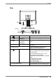
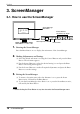
Rear
(9)
(10)
(11)
(12)
(14)
(15)
(13)
(9)
Power Connector Connect the power cord.
(10)
DVI-D Connector
(SIGNAL1)
Connect the optional digital cable.
(11)
D-Sub mini 15 pin
Connector
(SIGNAL2)
Connect the enclosed analog cable (MD-
C87)
(12)
RS-232C port Connect the enclosed touch panel cable
(FD-C38).
(13) Hole for TP1 Hole for installing the lead of the TP1
(Optional Touch Panel Pointer).
(14)
Security Lock Slot Allows for connection of a security cable.
This lock supports Kensington’s MicroSaver
security system.
For further information, please consult:
Kensington Technology Group
2855 Campus Drive, San Mateo, CA 94403
USA
Tel: 800-650-4242, x3348
Intl: 650-572-2700, x3348
Fax: 650-572-9675
http://www.kensington.com
(15) Stand (Detachable) The LCD monitor can be used with an other
stand by removing the stand (see page 25).
Bottom
1. INTRODUCTION
11