ENGLISH
SAFETY SYMBOLS This manual uses the safety symbols below. They denote critical information. Please read them carefully. WARNING Failure to abide by the information in a WARNING may result in serious injury and can be life threatening. CAUTION Failure to abide by the information in a CAUTION may result in moderate injury and/or property or product damage. Indicates a prohibited action. Indicates to ground for safety. Copyright© 2000 by EIZO NANAO CORPORATION. All rights reserved.
TABLE OF CONTENTS PRECAUTIONS.............................................................................. 4 1. INTRODUCTION .......................................................................... 10 2. ENGLISH 1-1. Features ..................................................................................................... 10 1-2. Package Contents ...................................................................................... 11 1-3. Controls & Connectors ...................................
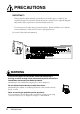
PRECAUTIONS IMPORTANT! ´ This product has been adjusted specifically for use in the region to which it was originally shipped. If operated outside the region to which it was originally shipped, the product may not perform as stated in the specifications. ´ To ensure personal safety and proper maintenance. Please read this section and the caution statements on the monitor (refer to the figure below).
WARNING ENGLISH ´ Keep small objects away from the monitor. Small objects may accidentally fall through the ventilation slots into the cabinet, leading to fire, shock, or equipment damage. ´ Keep liquids away from the monitor. Spillage into the cabinet may result in fire, electric shock, or equipment damage. If an object or liquid falls/spills into the cabinet, unplug the monitor immediately. Have the monitor checked by a qualified service engineer before using it again.
WARNING • Use the enclosed power cord. If using the power cord other than the enclosed one, follow these guidelines. [USA and Canada] Use a UL LISTED/CSA LABELED or CERTIFIED power cord set meeting the following specifications. * Rating: min. 125 V, 10 A *Length: max. 2.0 m * Plug type: NEMA 5-15P, Parallel blade, Grounding type, 125 V, 10 A * Type: SVT [Europe] Use a proper European standard approved power cord meeting the following specifications. * Rating: min. 250 V, 10 A *Length: max. 2.
WARNING ENGLISH ´ Install the monitor securely when attaching to an arm stand. When attaching an arm stand, please refer to the user’s manual of the arm stand and install the monitor securely with the enclosed screws. Not doing so may cause the monitor to come unattached, which may result in injury or equipment damage. When the monitor is dropped, please ask your dealer for advice. Do not continue using a damaged monitor. Using a damaged monitor may result in fire or electric shock.
CAUTION ´ Do not block the ventilation slots on the cabinet. * Do not place books or any other papers on the ventilation slots. * Do not install the monitor in a closed space. * Do not use the monitor lengthwise or upside down. Using the monitor in this way blocks the ventilation slots and prevents proper airflow, leading to fire or other damage. • Do not use the LCD monitor outdoors or inside a car. This LCD monitor has been made specifically for indoor use as a desktop monitor.
Suggestions for Maximizing Comfort ENGLISH ´ To lessen the chance of possible injury and to increase your comfort and productivity while you operate the monitor, we suggest the following: * Avoid less favorable body positioning. Sit back on the chair with your back straight. * Adjust the height of the chair so that the both soles touch the floor. * Adjust the height of your chair, monitor, or keyboard so that you can keep your wrists straight while typing. * Set the terminal slightly below eye level.
1. INTRODUCTION Thank you very much for choosing an EIZO Color LCD Monitor. 1-1.
1-2. Package Contents Please contact your local dealer for assistance if any of the listed items are missing or damaged. • Signal Cable (MD-C87/C100) • Power Cord • Connector Cover • 4 of 4 mm x 12 mm mounting screws • Rear Cover (attached to the monitor) • EIZO LCD Utility Disk • User’s Manual • Quick Reference • Warranty Registration Card ENGLISH • LCD Monitor • Please retain the packing materials for future transference. 1.
1-3. Controls & Connectors Front (1) (2) (1) (2) (3) (4) (5) (6) (7) (8) *1 12 (3) (5) (4) (6) (8) (7) ScreenManager™ Power Terminal Covers for the Optional peripheral Input Signal Selection Button Auto Adjustment Button Enter Button Control Buttons Power Button Power Indicator*1 Indicated color Power-on status Green Power is on Yellow Power save mode Slowly flashing Yellow Power is off (Main power is on) Regarding the power indicator for the “Off Timer”, see page 19. 1.
Rear ENGLISH (9) (9) (10) (11) (12) (13) (14) (15) (16) *2 *3 (10) (11) (12) (13) (14) (15) (16) Main Power Switch 4 Holes for Mounting an Arm-Stand*2 Stand (Detachable)*2 USB Downstream Ports x 4 Power Connector Security Lock Slot*3 D-Sub mini 15 pin Input Connector x 2 USB Upstream Port x 1 The LCD monitor can be used with an optional arm stand by removing the stand (see page 33). Allows for connection of a security cable. This lock supports Kensington’s MicroSaver security system.
2. CABLE CONNECTION 2-1. Before connecting Before connecting your monitor to the PC, change the display screen settings (resolution p. 43) and frequency) in accordance with the charts below.
2-2. Connecting the signal cable 1. ENGLISH • Be sure that the power switches of both the PC and the monitor are OFF. Remove the rear cover from the monitor. When removing the rear cover, push down the buttons while pulling. buttons 2. Plug the signal cable into the D-Sub connector at the rear of the monitor and the other end of the cable into the video connector on the PC. After connecting, secure the connection with the screw-in fasteners.
3. Plug the power cord into the power connector on the rear of the monitor. WARNING • Use the enclosed power cord. If using the power cord other than the enclosed one, follow these guidelines. [USA and Canada] Use a UL LISTED/CSA LABELED or CERTIFIED power cord set meeting the following specifications: * Rating: min. 125 V, 10 A * Length: max.2.
3. ScreenManager 3-1. How to use the ScreenManager Auto Adjustment Button Enter Button Control Buttons 1. Entering the ScreenManager Push the Enter button once to display the main menu of the ScreenManager. [ Main Menu ] 2. Making Adjustments and Settings (1) (2) (3) 3. Select the desired sub menu icon using the Control buttons and push the Enter button. The sub menu appears. Use the Control buttons to select the desired setting icon and push the Enter button. The setting menu appears.
• Double clicking the Enter button at any time also exits the ScreenManager menu. • Leaving the ScreenManager idle for 45 seconds or more will turn the adjustment off automatically, without saving the adjustments. 3-2. ScreenManager Adjustments and Settings The following table shows all the ScreenManager’s adjustment and setting menus.
3-3. Useful Functions Adjustment Lock Use the “Adjustment Lock” function to prevent any accidental changes. Unlocked function • Auto adjustment button adjustments and settings in the ScreenManager. • Adjustment of contrast and brightness by the control buttons. • Input signal selection button • To lock Press on the Auto adjustment button while switching on the monitor’s power button on the front panel.
4. ADJUSTMENT 4-1. Screen Adjustment Screen adjustments for the LCD monitor should be used in suppressing screen flickering and also for adjusting the screen to its proper position. There is only one correct position for each display mode. It is also recommended to use the ScreenManager function when first installing the display or whenever changing the system. For convenience, an easy set-up Program installed on the utility disk to assist in the set-up procedure is provided.
3. Adjust by using “Screen” menu in the ScreenManager. Select the “Clock” and eliminate the vertical bars by using the right and left of the control buttons. Do not continuously press the control buttons, as the adjustment value will change quickly and make it difficult to locate the most suitable adjustment point. If the horizontal flickering, blur or bars appear, proceed to “Phase” adjustment as follows. • When adjusting the “Clock,” the horizontal screen size will also change.
(3) The screen position is incorrect. Use the “Position” adjustment The correct displayed position of LCD monitor is decided because the number and the position of the pixels are fixed. The “Position” adjustment moves the image to the correct position. Select “Position” and adjust the position of the upper left corner of the image by using the up, down, right and left buttons in order to align the screen.
4. Set the Output signal range (Dynamic Range) of the signal. Perform the “Range Adjustment”p.43) [Auto] Push the Auto adjustment button on the front panel while displaying the “Range adjustment” menu to automatically adjust the range. The screen blanks for a moment, and adjusts the color range to display the whole color gradation of the current output signal. 5. Set the Contrast of the screen. Adjust the “Contrast” This controls the brightness for the each color (red, blue and green) at a same time.
4-2. Displaying a low resolutions The lower resolutions are enlarged to full screen automatically. Using the “Screen Size” function in the “Others” menu enables to change the screen size. 1. Change the screen size when displaying a low resolution. Select “Screen Size” Select the “Screen Size” in the others menu and select the screen size by using the up and down buttons. • Full • Enlarged • Normal Displays the picture on the screen in full, irrespective of the picture’s resolution.
2. Smooth the blurred texts of the enlarged screen. Adjust the “ Smoothing” ENGLISH Some lines of the texts or pictures may appear with the different size in the “Enlarged” mode or “Full Screen” mode. Select “Smoothing” in the screen menu and adjust by using the right and left buttons. • “Smoothing” is disabled when the screen is displayed in the following resolution. * 1600 x 1200 * The image size is doubled both in horizontally and vertically (i.e.
4-3. Color Adjustment The “ColorManagement”menu in the ScreenManager enables to change the color of the screen. Before the Color adjustment • Allow the LCD monitor to stabilize for at least 20 minutes before making color adjustments. • After finishing each adjustment in the custom mode, select “Save” icon to resister the adjustment. Otherwise, the adjustment will be lost. • The values shown in percentages represent the current level within the specific adjustment only.
2. To change the saturation. Adjust the “Saturation” • The “Saturation” adjustment may cause undisplayable color tone. 3. To change the flesh color, etc. Adjust the “Hue” The “Hue” can be selected from -20 ~ 20. To register the adjustment, select the “Save” icon and then push the enter button. • The “Hue” adjustment may cause undisplayable color tone. 4. To adjust each color (red, green and blue). Adjust the “Gain”p.
4-4. Power-save Setup This monitor complies with the VESA DPMSp.43) standard and adopts a power saving method, EIZO MPMS p.42), which works with a blank screen (totally black screen) like “Blank Screen” ScreenSaver software. 1. To use the PC’s power saving system (VESA DPMS ). [Procedure] (1)Set the PC’s power saving settings. (2)Select “VESA DPMS” in the “PowerManager” menu.
5. MAKING USE OF USB (Universal Serial Bus) This monitor provides a hub which supports the USB standard. When connecting to a USB compliant PC or another hub, the monitor functions as a hub to which the USB compliant peripherals can be easily connected. • PC equipped with USB ports or another USB hub connected to the USB compliant PC • Windows 98/2000 // Mac OS 8.5.1 or later • USB cable / MD-C93 (Optional) • The USB hub function may not work properly depending on the PC, OS or peripherals.
3. After setting up, the monitor’s USB hub is available for connecting USB compliant peripherals to the downstream ports of the monitor. Example of connection: Scanner Digital Camera USB Cable PC Printer Monitor Keyboard Mouse Downstream Downstream ports: Connect the cables from USB compliant peripherals such as a mouse, keyboard, etc. 30 5.
6. CONNECTING TWO PCs to THE MONITOR Two PCs can be connected to the monitor through the Signal 1 and the Signal 2 on the back of the monitor.
The priority input signal This function is used to select which PC will have priority to control the monitor when utilizing two PCs. The monitor constantly checks the input signals and switches automatically in accordance with the “Input Priority” setting (see table below). Once a priority is set, whenever a change of signal is detected at the selected input, the monitor will switch the input to that signal.
7. ATTACHING AN ARM STAND The LCD monitor can be used with an arm stand by removing the tilt stand and attaching the arm stand to the LCD monitor. NOTE * Use an arm stand with a 100 mm x 100 mm hole spacing on the arm mounting pad. * Use an arm stand that is able to support an object weighing 13.5 kg. ´ TÜV/GS approved arm stand. ´ Use an arm stand with sufficient stability (mechanical firmness) to support the weight of the monitor. ´ Use an arm stand remaining that position where it is manually moved.
2. Remove the stand by loosening the screws.(4 pcs of 4 x 10 S-Type Ni/Fe) 3. Attach an arm stand to the LCD monitor securely. WARNING ´ Install the monitor securely when attaching to an arm stand. When attaching an arm stand, please refer to the user’s manual of the arm stand and install the monitor securely with the enclosed screws. Not doing so may cause the monitor to come unattached, which may result in injury or equipment damage. When the monitor is dropped, please ask your dealer for advice.
8. TROUBLESHOOTING Problems 1. No picture • Indicator status: Off • Indicator status: Green • Indicator status: Yellow • Indicator status: Slowly flashing Yellow 2. Following messages appear. •Whenever an error signal message appears, the signal frequency will be displayed in red. (Example) Points to check with possible solutions Check that the power cord is correctly connected. If the problem persists, turn off the monitor power for a few minutes, then turn it back on and try again.
Problems Points to check with possible solutions 3. Display position is incorrect. Adjust the image position using the “Position”. (p.22) If the problem persists, use the graphics board’s utility software to change the display position if available. 4. Screen image is smaller or larger than the actual screen images. Adjust the resolution using the “Resolution”. (p.22) 5. Vertical bars of distortion appear. Decrease the vertical bars using the “Clock”. (p.21) 6. Horizontal bars of distortion appear.
Problems Points to check with possible solutions This is due to the characteristics of the panel itself, and not the LCD product. 12. Fingerprints remain on the screen. Leaving the screen white may solve the problem. 13. The “Smoothing” can not be selected. “Smoothing” is disabled when the screen is displayed in the following resolution. • 1600 x 1200 The image size is doubled both in horizontally and vertically (i.e.
Problems Points to check with possible solutions 17. Frequency does not change after installing “Monitor information file” in the attached utility disk on Windows 95/98/2000. Use the graphics board’s utility software to change the input signal frequency. 18. USB function cannot be setup. Check that the USB cable is correctly connected. Check that the PC and OS are USB compliant. (For verification of USB support, consult the manufacturer of each system.) Check the PC’s BIOS setting for USB.
9. CLEANING Periodic cleaning is recommended to keep the monitor looking new and to prolong its operation lifetime. ENGLISH WARNING ´ Keep liquids away from the monitor. Spillage into the cabinet may result in fire, electric shock, or equipment damage. If an object or liquid falls/spills into the cabinet, unplug the monitor immediately. Have the monitor checked by a qualified service engineer before using it again. CAUTION ´ Unplug the monitor before cleaning it.
10.SPECIFICATIONS LCD Panel Dot Pitch Scan Frequency Resolution Dot Clock (Max.) Display Colors Display Area Power Supply Power Consumption Input Connector Input Signal Signal registration Plug & Play Dimensions Dimensions (without stand) Weight Weight (without stand) Temperature Humidity USB specification USB standard Communication speed Downstream power supply USB ports 50 cm (19.
Default setting Default setting are as follows: 100 % 100 % 3 Standard mode/Off (Temperature) VESA DPMS Full Screen Signal 1 Disable On English ENGLISH •Contrast •Brightness •Smoothing •Color •PowerManager •Screen Size •Input Priority •Off Timer •Beep •Language Beeper settings Short beep Long beep 4 short beeps 2 short beeps every15 sec. · ScreenManager item selected. · ScreenManager parameter adjusted to minimum or maximum limit. · Input signal selection button pressed.
11.GLOSSARY Afterimage The Afterimage is particular to LCD monitors when the monitor screen is left on for a long period without use. The “Afterimage” can be removed gradually by changing the displayed image. Clock With the analog input signal display, the analog signal is converted to a digital signal by the LCD circuitry. To convert the signal correctly, the LCD monitor needs to produce the same number clock pulse as the dot clock of the graphics system.
Range Adjustment The Range Adjustment controls the level of output signal range to display the whole color gradation The LCD panel consists of a fixed number of pixel elements which are illuminated to form the screen image. The EIZO L771 monitor panel consists of 1600 horizontal pixels and 1200 vertical pixels. At a resolution of 1600 X1200, all pixels are used and the image is displayed as a full screen.
12.
APPENDIX / ANHANG / ANNEXE Preset Timing Chart for Analog input Timing-Übersichten für Analog Eingang Synchronisation des Signaux pour Analog numerique Based on the signal diagram shown below, 27 factory presets have been registered in the monitor's microprocessor. Der integrierte Mikroprozessor des Monitors unterstützt 27 werkseitige Standardeinstellungen (siehe hierzu die nachfolgenden Diagramme).
Mode VGA 640 x 480 VGA 720 x 400 Macintosh 640 x 480 Macintosh 832 x 624 Macintosh 1152 x 870 Macintosh 1280 x 960 VESA 640 x 480 VESA 640 x 480 VESA 640 x 480 VESA 800 x 600 VESA 800 x 600 VESA 800 x 600 VESA 800 x 600 VESA 800 x 600 VESA 1024 x 768 VESA 1024 x 768 VESA 1024 x 768 VESA 1024 x 768 VESA 1280 x 1024 VESA 1280 x 1024 VESA 1280 x1024 VESA 1600 x1200 VESA 1600 x 1200 VESA 1600 x1200 VESA 1600 x1200 Workstation 1152 x 900 Workstation 1152 x 900 xlvi APPENDIX Dot Clock Frequencies MHz H kHz
C: Back Porch D: Blanking Period E:Display Period F:Total Cycle V ms/ Line 1.048/ 33 1.111/ 35 1.114/ 39 0.784/ 39 0.568/ 39 0.482/ 36 H µs/ Dot 6.356/ 160 6.356/ 180 7.407/ 224 5.586/ 320 3.040/ 304 3.233/ 408 V ms/ Line 1.430/ 45 1.556/ 49 1.286/ 45 0.865/ 43 0.655/ 45 0.535/ 40 H µs/ Dot 25.442/ 640 25.422/ 720 21.164/ 640 14.524/ 832 11.520/ 1152 10.143/ 1280 V ms/ Line 15.254/ 480 12.712/ 400 13.714/ 480 12.549/ 624 12.667/ 870 12.841/ 960 H µs/ Dot 31.778/ 800 31.778/ 900 28.571/ 864 20.
Dimensions Abmessungen Dimensions 472 (18.6) mm (inches) 93.5 (3.7) 41.6 (1.6) 33.5 (1.3) 400.4 (15.7) 399 (15.7) 300.8 (11.8) 22° 3° 477.9 (18.9) 35.8 (1.4) 56.6 20.5 (2.2) (0.8) 120 (4.7) 270 (10.6) 25° 25° 51.5 (2.0) 101.4 (4.0) 218 (8.6) FRONT VIEW VORDERANSICHT VUE DE FACE TOP VIEW DRAUFSICHT VUE D'EN HAUT SIDE VIEW SEITENANSICHT VUE DE COTE Pin Assignment Pin-Belegung Affectation des Broches * D-Sub mini 15 pin connector Pin No. Signal Pin No.
MEMO APPENDIX APPENDIX
[Applicable to gray (standard color version only).] Congratulations! You have just purchased a TCO’99 approved and labelled product! Your choice has provided you with a product developed for professional use. Your purchase has also contributed to reducing the burden on the environment and also to the further development of environmentally adapted electronics products.
[Applicable to gray (standard color version only).] Environmental requirements Flame retardants Flame retardants are present in printed circuit boards, cables, wires, casings and housings. Their purpose is to prevent, or at least to delay the spread of fire. Up to 30% of the plastic in a computer casing can consist of flame retardant substances. Most flame retardants contain bromine or chloride, and those flame retardants are chemically related to another group of environmental toxins, PCBs.
For U.S.A, Canada, etc. (rated 100-120 Vac) Only FCC Declaration of Conformity We, the Responsible Party EIZO NANAO TECHNOLOGIES INC. 5710 Warland Drive, Cypress, CA 90630 Phone: 562 431 5011 declare that the product Trade name: EIZO Model: FlexScan L771 is in conf or mity wit confor ormity hP ar ation of this pr oduct is subject to the ffollo ollo Opera product ollowing two Par artt 15 of the FCC Rules.
For Europe, etc.