English User's Manual ® F67/FX·D7 T68/TX·D7 Color Display Monitor
CONTENTS PRECAUTIONS__________________________ 4 INTRODUCTION _________________________ 9 About This Manual ................................................... 9 Package Contents ................................................... 9 1 INSTALLATION ______________________ 10 1-1 Controls & Connectors .................................... 10 Front ................................................................................. 10 Rear ...........................................................................
2-5 Other Settings ................................................. 33 Degaussing ..................................................................... Input Priority .................................................................... Beep ................................................................................ Menu Position, Menu Contrast ........................................ Signal Filter ..................................................................... Reset .............................
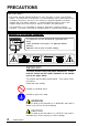
PRECAUTIONS IMPORTANT! * This product has been adjusted specifically for use in the region to which it was originally shipped. The performance of the product, (i.e. picture geometry, picture positioning and color convergence and purity in the case of color monitors) is optimally adjusted to the earth's magnetic field of the specific destination. If operated outside the region to which it was originally shipped, the product may not perform as stated in the specifications.
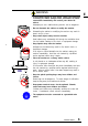
WARNING • If the monitor begins to emit smoke, smells like something is burning, or makes strange noises, disconnect all power connections immediately and contact your dealer for advice. Attempting to use a malfunctioning monitor can be dangerous. • Do not dismantle the cabinet or modify the monitor. Dismantling the cabinet or modifying the monitor may result in electric shock or burn. • Keep small objects away from the monitor.
• Use the enclosed power cord. If using the power cord other than the enclosed one, use the following cord. In USA and Canada: * Rating: min. 125 V, 10 A * Length: max. 2.1 m * Type: SVT * Plug type:NEMA 5-15P, Parallel blade, Grounding type, 125 V, 10 A In Europe: * Rating: min. 250 V, 10 A * Length: max. 2.1 m * Type: H05VV-F 3G 1 mm 2 Use a plug type approved by the country where you use. Failure to do so may cause fire or electric shock.
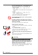
• Handle with care when carrying the monitor Note that the monitor is heavier at the front than at the rear. Do not move it alone. Always work with another person. OK The screen is optically coated to reduce glare. Keep hard objects (such as buttons, tie pins, and other clothing accessories) away from the screen surface to prevent scratches. • Set the monitor in an appropriate location. * Do not install in a dusty or humid environment.
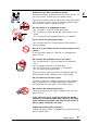
For users of the EIZO optional i·Sound sound unit and i·Station USB hub • When adjusting the viewing angle of the monitor, do not do so by handling the sound unit or USB hub. Adjusting the monitor in this way may break the unit or cause bodily injury. Others • Do not install the monitor within an area subject to strong magnetic fields (for example, in the vicinity of a speaker, except the optional i·Sound unit, or a high-voltage transformer).
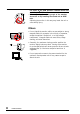
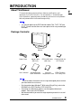
INTRODUCTION About This Manual This manual explains the precautions, features, specifications, and operation of your EIZO monitor. For convenience, a “ScreenManager Quick Reference” guide has been included which shows how to implement basic adjustments with the ScreenManager utility. • This manual applies to the EIZO monitor models: T68, TX·D7, F67 and FX·D7. Please note that there are some points which vary according to the model.
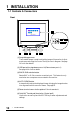
1 INSTALLATION 1-1 Controls & Connectors Front (1) ScreenManager menu The ScreenManager is used to adjust the image of the monitor. Adjustments are made using the Control Pad (6) shown in diagram. See page 14 for further details. (2) USB port with a drop down access lid (Downstream port x 1) See page 44 for further details. (3) BNC/D-SUB selection button Selects BNC or D-Sub connector as active input. This feature is only used when two computers are connected to the monitor.
(7)Power indicator Indicates the power-on status, as follows: Solid green: Power is ON (normal mode) Flashing green: PowerManager Mode 1 (power-saving mode) Yellow: PowerManager Mode 2 (maximum power-saving) E (8)Power switch Switches the monitor’s power ON and OFF. Rear (1)Power connector Use the supplied power cord only. (2)D-Sub mini 15 pin input connector (3)BNC input connector (4)Termination switch Allows multiple monitors to be chained together (Default termination is 75 Ω).
1-2 Connecting the monitor to the PC 1) Be sure that the power switches of both the PC and the monitor are OFF. 2) Plug the power cord into the power connector at the rear of the monitor. Then plug the other end of the cord into a power outlet. 3) Plug the signal cable into the connector at the rear of the monitor. • When connecting the signal cable or cable adapter, first check that the shape at the cable side matches the shape at the connecting side.
Macintosh E You must connect an optional Macintosh adapter to the PC before connecting the signal cable. D-Sub 15 pin D-Sub mini 15 pin D-Sub mini 15 pin Macintosh MD-C87 (enclosed) Macintosh Adapter (Optional) 5) Turn on the monitor power first, then switch on the PC power. The monitor’s power indicator (LED) will light up (green). The monitor will warm up briefly, then display an image. Whenever you finish your operation, turn off the PC and the monitor.
2 SCREEN ADJUSTMENT 2-1 How to use the ScreenManager ScreenManager Menus ScreenManager consists of a main menu and six sub menus: “Screen”, “Color”, “PowerManager”, “Others”, “Information” and “Language.” Animated icons on each menu allow for easy adjustment. Main menu • The menu message for the ScreenManager can be displayed in six languages: English, German, French, Italian, Spanish and Swedish. First, select the preferred language through the “Language” menu.
Menus Functions Reference Page 28 Power saving settings. Page 33 Degauss, Input-signal priority selection for two signal connections, Beep ON/OFF, ScreenManager menu position, Contrast adjustment, Signal filter setting and Reset to defaults. This menu shows the current ScreenManager settings. The menu contains four pages.
Press the ENTER key to display the ScreenManager Main menu. Enter the Settings Use the Control pad (the four arrow keys and the ENTER key) to make the required adjustments and settings. Arrow keys ENTER key Save & Exit To return to the previous menu, select the Return icon (or push the “down” arrow key twice), then push the ENTER key. To save settings and exit the ScreenManager, select the Exit icon and press the ENTER key.
Before entering the ScreenManager, brightness and contrast can be adjusted directly by moving the Control pad. To record the new setting and exit the ScreenManager, press the Enter key. (The brightness and contrast functions are also available in the ScreenManager “Screen” menu.) See the diagram described below for adjustment directions.
2-2 Imaging adjustment Using the AUTO-SIZING button After connecting the monitor to the PC, first press the AUTO-SIZING button on the front panel. The AUTO-SIZING function centers the displayed image, aligning the image’s borders with respect to the monitor frame. In general, press the AUTO-SIZING button whenever changing the graphics board or the resolution or when image size and/or position is incorrect.
- Screen menu - E All of the icons shown in the ScreenManager “Screen” menu are described below. • Allow the monitor to stabilize for at least 30 minutes before making image adjustments. Brightness, Contrast, Size, Position These functions are used to adjust the brightness, contrast, size and position of the screen. Proper adjusting for brightness & contrast 1) Set the brightness and contrast to their maximum settings. 2) Set the display area to the minimum size.
• If you use the white text against a black background like DOS text, we recommend that you set the brightness to its maximum setting because the dark setting will result in eye strain due to high character contrast. Geometry, Tilt, Uniformity Image distortion, tilting and/or the imbalance of brightness/whiteness over the entire screen may be caused by the Earth’s magnetic field depending on the direction the monitor is facing.
Convergence Displayed characters and images may appear fuzzy or have tinges of red, green, or blue if the electron beams do not converge correctly. These can be adjusted by the convergence adjustment feature in the ScreenManager. What is convergence? Convergence is the monitor’s ability to precisely illuminate specific phosphors and line them up properly in order to produce pure color. In order to properly adjust convergence, it is best to have an image that makes it easy to see any convergence error.
Moiré Reduction What is moiré? Moiré refers to an interference pattern of dark wavy lines on the screen. It is not a defect, but rather an interference phenomenon caused by the relationship between the phosphor layout and the imaging signal. Moiré is often an indication of a good focus level. Moiré is particularly noticeable when using a light-gray or every-other-dot pattern background. Although moiré can not be eliminated, it can be reduced with the moiré reduction feature.
2-3 Color Adjustment E - Color menu - Outline EIZO monitors have incorporated two color adjustment mode, standard and custom. The “Standard” mode allows the adjustment of the color spectrum. The “Custom” mode allows extensive controls over the colors of the displayed image on the screen. All adjustments for either mode can be made quickly and easily through the ScreenManager “Color” Menu - offering a tool to create customized color environment.
• Each monitor is slightly different, if two monitors are set to the same color temperature value (i.e. 6500K), they may not necessarily look the same. Adjusting the Standard mode Color Temprature • Users should allow at least 30 minutes for the monitor to stabilize before setting the color adjustments or color matching. Procedure 1) Go to the “Color” menu. 2) Select the “Standard mode” setting from the “Color mode” menu. 3) Select the “Temperature” icon. A color temperature bar will appear.
Adjusting the Custom mode E Cutoff and Gain adjustments Monitors use red, green and blue (R, G, and B) to convey color information. They use an additive method to combine different amounts of the primary colors to produce a desired color. In other words, monitors start with no light (black) and add percentages of red, green and blue to make colors. White is usually produced by adding the same amount of all three colors, where black is usually produced by adding no color.
a) Select the “Temperature” icon from the sub menu. b) Select the temperature as desired by moving the arrow keys in any direction. 4) Adjust the Cutoff Cutoff The Cutoff adjustment is the most powerful adjustment. It alters the starting point (the black level) and the ending point (the white level). If the Cutoff level for color is raised or lowered, black, white, and all levels between are raised or lowered by the same degree.
• These diagram explains how the color curves were changed for the best adjustment in steps 4 and 5. Adjust the black level so that the low end of the curve for each color (R,G,B) is equal as see picture 2. Adjust the white level so that the high end of the curve for each color (R,G,B) is equal as see picture 3. E This setup gives the best color balance.
2-4 Power-save Setup - PowerManager menu - What is PowerManager? The PowerManager feature automatically reduces the monitor’s power consumption during idle periods, in accordance with the PCs ScreenSaver software. There are two PowerSaving modes in the EIZO PowerManager: Mode 1 and Mode 2. Even if the monitor is in a power saving mode, it will return to a normal display immediately when the mouse or keyboard is operated. The EIZO PowerManager functions comply with NUTEK and VESA DPMS standard.
Set-up Procedure Set the monitor’s power-save environment to match the PC’s ScreenSaver software. • For the PC setup, please refer to the user’s manuals for the PC and graphics board. There are two power-save settings for the monitor. “VESA DPMS” system works with the VESA DPMS signal. “NUTEK”s system works with a screen saver software and Energy Saver for Macintosh which blanks the screen (totally black screen). Set the monitor to match the PC’s power-saving software, as follows.
VESA DPMS System 1) First, make the appropriate settings for the PC. (See note, page 29.) 2) Then select “VESA DPMS”. 3) Set the delay period, which is the interval that the monitor will wait after receiving a power-save signal from the PC, before entering into Mode 1 or Mode 2. VESA DPMS power-saving method VESA DPMS utilizes four signals: ON, STANDBY, SUSPEND, and OFF. The monitor detects these signals from the graphics board and executes power-saving accordingly, as illustrated below.
NUTEK System E 1) First make the appropriate ScreenSaver settings (Macintosh/Energy Saver) for the PC. 2) Then select “NUTEK”. 3) Set the delay time, which is the interval between the time that the ScreenSaver (Macintosh/EnergySaver) blanks the screen and the time that the monitor enters Mode 1. 4) Set the Mode 1 duration time which is the user definable time (0-60 minutes) before the monitor enters Mode 2.
What is VESA DPMS? The acronym VESA stands for “Video Electronics Standards Association,” and DPMS stands for “Display Power Management Signaling.” DPMS is a communication standard that PCs and graphics boards use to implement power savings at the monitor side. What is NUTEK? NUTEK is the acronym for the Swedish National Board for Industrial and Technical Development, an organization that works to promote power-saving technologies.
2-5 Other Settings E - Others menu - All of the icons shown in the ScreenManager “Others” menu are described below. Degaussing The monitor automatically degausses every time the power is turned ON and every time it is reactivated from the PowerManager power-saving Mode 2. A degaussing function is provided in the ScreenManager for use at other times. Note that the image vibrates slightly while degaussing is in progress, but will return to normal when degaussing is completed.
In the case of only one signal being present at either input, the monitor automatically detects and displays that signal. Priority setting D-Sub BNC Manual Performance If signals from both inputs are present, the monitor gives preference to D-Sub for the cases shown below: • When the power of the monitor is turned ON (see note 1). • When the signal input to D-Sub is changed even if active input was BNC.
Menu Position, Menu Contrast Use these functions to adjust the position and contrast of the ScreenManager menu. The menu contrast can be set from level 0 (minimum setting) to 5 (maximum setting). Signal Filter This monitor provides two display modes according to the characteristics of each graphics board for displaying the image properly.
3 TROUBLESHOOTING 3-1 Troubleshooting This page presents problems that can be corrected by the user. If a problem persists even after applying the suggested remedies, contact an EIZO dealer. n Problems caused by incorrectly setting of the termination switch Problems 1) Misconvergence of colors. 2) Focus is dull. 3) PowerManager does not work properly in VESA setting. 4) Slight shadow appears on the edges of the screen image or text. (only for the BNC connections.
Problems 5) “Out of range” error message appears. (Example) Points to check with possible solutions • Use the graphics board’s utility software to change the frequency setting. (Refer to the manual of the graphics board.) • Whenever an error signal message appears, the signal frequency will be displayed in red. • Error messages will remain on the screen for 30 seconds, and then disappear. An error message may not appear at all if the signal frequency is extremely high or extremely low.
Problems Points to check with possible solutions 4) • The image vibrates on the screen. • Use of the “Moiré Reduction” feature may cause a slight vibration. To eliminate the vibration, switch the feature OFF or reduce the moiré reduction level. • A slight shaking movement See page 22. of the screen image or text. • Check that the signal cable is properly connected to the graphics board or PC. • Check that the graphics board is correctly mounted in the PC. • The signal cable might be damaged.
Problems Points to check with possible solutions 7) Moiré patterns are distracting. • Go to the ScreenManager’s “Screen” menu. Switch on the moiré reduction feature and adjust as necessary. See page 22. 8) The image is flickering. • Flicker will occur with interlaced scanning, or noninterlaced scanning with a low refresh rate. All EIZO monitors are capable of reproducing high refresh rates for non-interlaced scanning.
Problems 3) Misconvergence of colors. (red, green, blue) Points to check with possible solutions • Allow 30 minutes for the monitor to warm up. • Adjust the convergence using the Convergence feature in the ScreenManager’s Screen menu. See page 21. • This problem can occur when using a BNC connection and the termination switch is set incorrectly. The termination switch should be set to 75 Ω for connection to a single monitor.
Problems Points to check with possible solutions • A solid-color screen (i.e. red, green, blue) may appear for an instant while ing the auto-sizing function, this phenomenon is not a failure. 5) Characters are too large. E perform- • Change the resolution of the graphics board to a higher setting. (Refer to the manual for the graphics board or PC.) What is Resolution? Resolution is expressed as the number of dots (pixels) displayed on the screen.
Problems 7) Faint black vertical lines are visible on the screen. (only T68) Points to check with possible solutions • The aperture grille may be misaligned. Shock or vibration during transport may, in some cases, cause the aperture grille to fall out of alignment. The problem will appear as one or more faint black lines across the screen. If this problem occurs, it may be able to solved by: • degaussing the screen, or • lightly tapping (do not hit) the side of the monitor.
4 GETTING THE MOST FROM YOUR MONITOR 4-1 Adjustment Lock E The ScreenManager operation can be disabled by holding down the AUTO-SIZING button while switching on the monitor’s power. This will disable (“lock”) the ScreenManager and AUTO-SIZING button, protecting from accidental changes. To unlock the buttons: switch the power off, then hold down AUTOSIZING button once again and turn the power back on.
Ô Sound Unit 4-3 Optional i·SoundÔ The optional speaker system i·Sound connects directly to the monitor and can be used to support multimedia applications. The unit includes a microphone function. For details, consult EIZO dealers. 4-4 Making use of USB (Universal Serial Bus) - For USB compliant system environmentsThis monitor provides a hub which supports the USB standard.
• When connecting the USB cable, check that the shape of the connector at the USB cable side matches the shape at the connecting side. Upstream connector Upstream Port: Connect the USB compliant PC or another hub using the EIZO USB cable (MD-C93). (3) "EIZO USB Hub" appears on the screen. Insert the Windows 98 CDROM and click "OK" in the "Insert Disk" window. Follow the instruction of the window.
Connect the USB compliant peripherals to the downstream ports of the monitor: (Example of connection) EIZO USB Cable (MD-C93) Scanner Printer Monitor Digital Camera PC Keyboard Mouse Front port (Example) Rear port (Example) Downstream ports: Connect the cables from USB compliant peripherals such as a mouse, keyboard, etc. Downstream connector USB Specifications 46 4 USB standard Rev. 1.0 complied self-powered hub Downstream power supply 500 mA for each (Max.
Troubleshooting Problems Points to check with possible solutions 1) • USB function cannot be setup. Check that the USB cable is correctly connected. Check that the PC and OS is compliant to the USB. (For the USB support of the system, consult the manufacturer of each system.) Check the PC’s BIOS setting for the USB. (For details, refer to the manual of the PC.) Check that the USB cable is correctly connected. 2) • PC is hung up.
5 CLEANING WARNING • Keep liquids away from the monitor. Spillage into the cabinet may result in fire, electric shock, or equipment damage. If an object or liquid falls/spills into the cabinet, unplug the monitor immediately. Have the unit checked by a qualified service engineer before using it again. Using the monitor in this condition could cause serious injury or equipment damage. CAUTION • To ensure safety, always unplug the monitor before cleaning it. Failure to do so may result in electric shock.
6 SPECIFICATIONS T68/TX·D7 E Electrical Specifications CRT CRT AG Pitch Scan Frequency Horizontal: Vertical: Max. Active Display Area Power Supply Power Consumption Normal/Max: PowerManager Mode 1: PowerManager Mode 2: Input Connector Recommended Resolution Input Signal Sync: Video: 50 cm (19 inch) class, 90° deflection Aperture Grille type CRT with Anti-Reflective SuperErgoCoat® 0.25 mm (center), 0.27 mm (edges) 30 kHz-96 kHz (Automatic) 50 Hz-160 Hz (Automatic) 362 mm (H) × 271 mm (V) (14.
F67/FX·D7 Electrical Specifications CRT CRT Dot Pitch Scan Frequency Horizontal: Vertical: Max. Active Display Area Power Supply Power Consumption Normal/Max: PowerManager Mode 1: PowerManager Mode 2: Input Connector Recommended Resolution nput Signal Sync: Video: 50 cm (19 inch) class, 90° deflection FS type CRT with Anti-Reflective SuperErgoCoat® 0.26 mm 30 kHz-96 kHz (Automatic) 50 Hz-160 Hz (Automatic) 363 mm (H) × 272 mm (V) (14.2” (Η) × 10.7” (V)) (Diagonal: 453 mm (17.
i
APPENDIX Pin Assignment Pin-Belegung Affectation des Broches D-Sub mini 15 pin connector Pin No. Signal Pin No. Signal 1 Red video 9 No pin 2 Green video 10 Ground 3 Blue video 11 (shorted) 4 Ground 12 Data 5 No pin 13 H. Sync 6 Red ground 14 V. Sync 7 Green ground 15 Clock 8 Blue ground BNC connector Connector H.Sync V.
Preset Timing Vordefinierte Timing-Werte Signaux prédéfinis 2 factory presets shown below have been registered in the monitor’s microprocessor. Der Monitor unterstützt 2 werkseitig vorgegebene Timing-Werte (siehe unten). Diese Werte sind im Mikroprozessor Ihres Monitors gespeichert. Les deux signaux ci-dessous ont été enregistrés en usine dans le microprocesseur du moniteur. Resolution Frequencies Interlace Sync Polarity Video Signal fH (kHz) fV (Hz) Level VGA (text) 720 x 400 31.47 70.
Congratulations! You have just purchased a TCO’99 approved and labelled product! Your choice has provided you with a product developed for professional use. Your purchase has also contributed to reducing the burden on the environment and also to the further development of environmentally adapted electronics products.
Environmental requirements Flame retardants Flame retardants are present in printed circuit boards, cables, wires, casings and housings. Their purpose is to prevent, or at least to delay the spread of fire. Up to 30% of the plastic in a computer casing can consist of flame retardant substances. Most flame retardants contain bromine or chloride, and those flame retardants are chemically related to another group of environmental toxins, PCBs.
For Europe, etc. (220-240 Vac) Only CE Marking Declaration of Conformity Kind of equipment: Type-designation: Monitor T68 (Model No. MA-1991), TX·D7 (Model No.
For Europe, etc. (220-240 Vac) Only CE Marking Declaration of Conformity Kind of equipment: Type-designation: Monitor F67 (Model No. MA-1990), FX·D7 (Model No.
For U.S.A, Canada, etc. (rated 100-120 Vac) Only FCC Declaration of conformity We, the Responsible Party EIZO Nanao Technologies Inc. 5710 Warland Drive, Cypress, CA 90630 Phone: (562) 431-5011 declare that the product Trade name: EIZO Model: FlexScan FX·D7/Model No: MA-1990 Model: FlexScan TX·D7/Model No: MA-1991 is in conformity with Part 15 of the FCC Rules.