User’s Manual Monochrome LCD Monitor
English SAFETY SYMBOLS This manual uses the safety symbols below. They denote critical information. Please read them carefully. WARNING Failure to abide by the information in a WARNING may result in serious injury and can be life threatening. CAUTION Failure to abide by the information in a CAUTION may result in moderate injury and/or property or product damage. Indicates a prohibited action. Indicates to ground for safety. Copyright© 2002 by EIZO NANAO CORPORATION. All rights reserved.
English TABLE OF CONTENTS PRECAUTIONS.................................................................................... 4 1. INTRODUCTION ..................................................................................... 9 1-1. Features....................................................................................................... 9 1-2. Package Contents ........................................................................................ 9 1-3. Controls & Connectors ........................
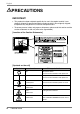
English PRECAUTIONS IMPORTANT! • This product has been adjusted specifically for use in the region to which it was originally shipped. If operated outside the region to which it was originally shipped, the product may not perform as stated in the specifications. • To ensure personal safety and proper maintenance, please read this section and the caution statements on the unit (refer to the figure below).
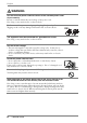
English WARNING If the unit begins to emit smoke, smells like something is burning, or makes strange noises, disconnect all power connections immediately and contact your dealer for advice. Attempting to use a malfunctioning unit may result in fire, electric shock, or equipment damage. Do not open the cabinet or modify the unit. Opening the cabinet or modifying the unit may result in fire, electric shock, or burn. Refer all servicing to qualified service personnel.
English WARNING Use the enclosed power cord and connect to the standard power outlet of your country. Be sure to remain within the rated voltage of the power cord. Not doing so may result in fire or electric shock. To disconnect the power cord, grasp the plug firmly and pull. Tugging on the cord may damage and result in fire or electric shock. The equipment must be connected to a grounded main outlet. Not doing so may result in fire or electric shock. Use the correct voltage.
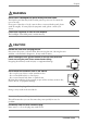
English WARNING Do not touch a damaged LCD panel directly with bare hands. The liquid crystal that may leak from the panel is poisonous if it enters the eyes or mouth. If any part of the skin or body comes in direct contact with the panel, please wash thoroughly. If some physical symptoms result, please consult your doctor. Follow local regulation or laws for safe disposal. The backlight of the LCD panel contains mercury. CAUTION Handle with care when carrying the unit.
English CAUTION Unplug the unit before cleaning it. Cleaning the unit while it is plugged into a power outlet may result in electric shock. If you plan to leave the unit unused for an extended period, disconnect the power cord from the wall socket after turning off the power switch for the safety and the power conservation.
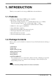
English 1. INTRODUCTION Thank you very much for choosing an EIZO Monochrome Monitor. 1-1. Features • DVI (p. 41) Digital input (TMDS (p. 42)) compliant • Resolution: 1 M pixels (1280 x 1024) Horizontal scanning frequency: 27 - 82 kHz (Digital input: 27 - 64 kHz) Vertical scanning frequency: 50 - 85 Hz (1280 x 1024 ~ 75 Hz) (Digital input: 60 Hz (VGA text: 70 Hz)) • RGB Color video signal compatibility • Auto Adjustment compliant • USB (Universal Serial Bus) hub supported (p.
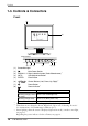
English 1-3.
English Rear (9) (10) Bottom (11)(12)(13) (14)(15) (16) (9) *4 Height Adjustable Stand (Detachable) *5 Security Lock Slot (10) *6 (11) SENSOR Serial Port, Photo Sensor Connector (Mini DIN 8 pin) *7 IN Serial Port, Remote IN (Mini DIN 6 pin) (12) (13) (14) (15) DVI-I Input Connector USB Port (2 Downstream) USB Port (1 Upstream) (16) Power Connector *4 The LCD monitor has the capability of the Portrait/Landscape display. (The panel pivots in the counter-clockwise direction 90°.
English 2. CABLE CONNECTION 2-1. Before connecting Before connecting your monitor to the PC, change the display screen settings (resolution p. 42) and frequency) in accordance with the charts below. NOTE • When your computer and display support VESA DDC, the suitable resolution and the refresh rate are set by just plugging your display into the computer without any manual settings.
English 2-2. Connecting the signal cable NOTE • Be sure that the power switches of both the PC and the monitor are OFF. 1. Plug the signal cable into the connector at the rear of the monitor and the other end of the cable into the video connector on the PC. After connecting, secure the connection with the screw-in fasteners.
English [Signal selection] Please use the signal select button on the front panel. (1) The selection menu appears by pressing the button for more than 2 seconds. (2) Choose “Monochrome” by up and down keys. SIGNAL AUTO 1-2 ENTER Signal selection button (Color / Monochrome) Digital Input Signal Cable Signal Cable (FD-C04 enclosed) Connector Video Output Connector DVI PC Monochrome digital graphics board NOTE • Only TMDS DATA1 (Green) of video signal data is displayed.
English Cable Holder 4. Plug the other end of the power cord into a power outlet. WARNING Use the enclosed power cord and connect to the standard power outlet of your country. Be sure to remain within the rated voltage of the power cord. Not doing so may result in fire or electric shock. The equipment must be connected to a grounded main outlet. Not doing so may cause in fire or electric shock. Not doing so may result in fire or electric shock. 5.
English 3. ScreenManager 3-1. How to use the ScreenManager Control Buttons Left, Down, Up, Right SIGNAL AUTO 1-2 Auto Adjustment button 1. ENTER Enter button Entering the ScreenManager Push the Enter button once to display the main menu of the ScreenManager. [Main Menu ] 2. Making Adjustments and Settings (1) Select the desired sub menu icon using the Control buttons and push the Enter button. The sub menu appears.
English 3-2. ScreenManager Adjustments and Settings. The following table shows all the ScreenManager’s adjustment and setting menus. “*” indicates adjustments of analog input only and “**” indicates digital input only. Main menu Screen Sub menu Reference Clock * Phase * 4-1. Screen Adjustment (p.19) Position Resolution * Range Adjustment Brightness Smoothing * Signal Filter *1 Unlock the lock (p.
English 3-3. Useful Functions Adjustment Lock Use the “Adjustment Lock” function to prevent any accidental changes. Locked function • Settings in the ScreenManager. • Signal selection button (Color/Monochrome) • Adjustment of brightness by the control buttons. • To lock Switch off the monitor’s power by the power button on the front panel. Press on the Auto adjustment button while switching on the monitor’s power.
English 4. ADJUSTMENT 4-1. Screen Adjustment NOTE • Allow the LCD monitor to stabilize for at least 20 minutes before making image adjustments. When connecting the digital graphics board, see page 22. Analog Input Screen adjustments for the LCD monitor should be used in suppressing screen flickering and also for adjusting the screen to its proper position. There is only one correct position for each display mode.
English NOTE • More precise adjustment is available for using the “Screen Adjustment program” utility software. It can be downloaded from the EIZO homepage (http://www.eizo.com/). 3. Adjust by using menu in the ScreenManager. (1) Vertical bars appear on the screen → Use the (p.41) adjustment. Select the “Clock” and eliminate the vertical bars by using the right and left of the control buttons.
English (3) The screen position is incorrect. Use the adjustment. → The correct displayed position of the monitor is decided because the number and the position of the pixels are fixed. The adjustment moves the image to the correct position. Select and adjust the position of the upper left corner of the image by using the up, down, right and left buttons in order to align the screen.
English 4. Adjust the output signal range (Dynamic Range) of the signal. → Use the (p.41) of menu. This controls the level of output signal range to display the whole gradation (256 steps). [Procedure] Push the Auto adjustment button on the front panel while displaying the menu to automatically adjust the range. The screen blanks for a moment, and adjusts the color range to display the whole gradation of the current output signal. 5.
English 4-2. Displaying low resolutions Using the function in the menu enables to change the screen size of lower resolution (i.e. except 1280 x 1024). 1. Enlarge the screen size when displaying a low resolution. → Select the . Select the in the menu and select the screen size by using the up and down buttons. Menu Function Full Screen Displays the picture on the screen in full, irrespective of the picture’s resolution.
English 3. Set the brightness of the black area surrounding the displayed image. → Set the . In the mode or mode, the outer area (border) is usually black. Select in the menu and adjust by using the right and left buttons. Border 24 4.
English 4-3. Power-save Setup The menu in the ScreenManager enables to set the power-save setup. NOTE • Do your part to conserve energy, turn off the monitor when you are finished using it. Disconnecting the monitor from the power supply is recommended to save energy completely. • Even if the monitor is in a power saving mode, USB compliant devices function when they are connected to the monitor’s USB (both the upstream and the downstream ports).
English 5. CALIBRATION The calibration is available when using the specified optional calibration kit (p.38). Accessories for Calibration Kit • Photo Sensor x 1 • Maintenance cable x 4 • Calibration Software Mini DIN 6 pin Mini DIN 8 pin Photo Sensor Maintenance cable PC D-Sub 9 pin 1. Confirm the graphics board settings (If the graphics board has the settings below). Please read the User’s manual of the graphics board in details. • Set the output signal level to “Linear” or "Static Gray".
English NOTE • Lead the maintenance cables into the cable holder after connecting (p.14). • Brightness adjustment is not available while the calibrating the monitor. • After the calibration, brightness and other functions are automatically locked. Please refer to the procedure below to unlock. Unlock function after calibration After the calibration, brightness and other functions are automatically locked. Unlock function is available by using ScreenManager.
English 6. MAKING USE OF USB (Universal Serial Bus) This monitor provides a hub which supports the USB standard. When connecting to a USB compliant PC or another hub, the monitor functions as a hub to which the USB compliant peripherals can be easily connected. Required system environment • PC equipped with USB ports or another USB hub connected to the USB compliant PC • USB Cable NOTE • The USB hub function may not work properly depending on the PC, OS or peripherals.
English After connecting the USB cable, the USB function can be set up automatically. 3. After setting up, the monitor’s USB hub is available for connecting USB compliant peripherals to the downstream ports of the monitor. Connecting Examples Monitor PC Keyboard Mouse Printer Downstream Downstream ports: Connect the cables from USB compliant peripherals such as a mouse, keyboard, etc. Keyboard Printer 6.
English 7. ATTACHING AN ARM STAND The LCD monitor can be used with an arm stand by removing the tilt stand and attaching the arm stand to the LCD monitor. NOTE • Use an arm stand that satisfies the followings. - When using the LCD monitor with an arm stand, the arm stand must be VESA approved: *Use an arm stand with a 100 mm x 100 mm hole spacing on the arm mounting pad. *Weight: Use an arm stand that is able to support an object weighting 13.5 kg (29.8 lbs.). - TÜV/GS approved arm stand.
English 4. Remove the tilt stand by loosening the screws. (4 pcs of M4 x 15 mm BZn/Fe) 5. Attach an arm stand to the LCD monitor securely. Arm-stand M4 Mounting Screws: M4 x 15 (mm) BZn/Fe 7.
English 8. TROUBLESHOOTING If a problem persists even after applying the suggested remedies, contact an EIZO dealer. • No picture problems → See No.1 ~ No.2 • Imaging problems → See No.3 ~ No.13 • Other problems → See No.14 ~ No.17 • USB problems → See No.18 ~ No.19 Problems 1. No picture • Indicator status: Off • Indicator status: Green • Indicator status: Orange • Indicator status: Slowly flashing Orange • Indicator status: Flashing Orange (twice for each) 2.
English Problems Points to check with possible solutions 3. Display position is incorrect. ! Adjust the image position using the (p.21) If the problem persists, use the graphics board’s utility software to change the display position if available. 4. Screen image is smaller or larger than the actual screen images. ! Adjust the resolution using the (p.21) 5. Vertical bars of distortion appear. ! Decrease the vertical bars using the . (p.20) 6.
English Problems 10. The screen is too bright or too dark. Points to check with possible solutions ! Adjust the (The backlight of the LCD monitor has a fixed life span. When the screen becomes dark or begins to flicker, please contact your dealer.) ! Confirm the followings if the screen is too dark. • In the case of connecting to the analog graphics board, choose color by the signal select button on the front panel. 11. Afterimages appear.
English Problems Points to check with possible solutions 17. The Auto adjustment button does not ! The adjustment lock is probably on. To unlock: switch the LCD monitor off. Then, while pressing operate. the Auto adjustment button, switch the power on. (p.18) ! The Auto sizing function is intended for use on the Macintosh and on AT-compatible PC running Windows. It may not work properly in either of the following cases. • When running an AT-compatible PC on MS-DOS (Not windows).
English 9. CLEANING Periodic cleaning is recommended to keep the monitor looking new and to prolong its operation lifetime. NOTE • Never use thinner, benzene, alcohol (ethanol, methanol, or isopropyl alcohol), abrasive cleaners, or other strong solvents, as these may cause damage to the cabinet or LCD panel. Cabinet To remove stains, wipe the cabinet with a soft, lightly moistened cloth using a mild detergent. Do not spray wax or cleaner directly into the cabinet.
English 10. SPECIFICATIONS LCD Panel 46 cm (18.1 inch), TFT Monochrome LCD panel Anti-Glare Hard coating 2H Viewing Angle Horizontal: 170°, Vertical: 170° Dot Pitch 0.2805 mm Horizontal Scan Frequency Analog: 27 ∼ 82 kHz (Automatic), Digital: 27 ~ 64 kHz Vertical Scan Frequency Analog: 50 Hz ∼ 85 Hz (Automatic) (1280 x 1024: 50 Hz ∼ 75 Hz) Digital: 60Hz, (VGA TEXT : 70Hz) Resolution 1M pixels (1280 dots x 1024 lines) Dot Clock (Max.
English Certifications and Standards TÜV Rheinland /GM, CB, NRTL/C-TÜV, CE (93/42/EEC), FCC-A, Classification of equipment Type of protection against electric shock: Class I EMC class: EN60601-1-2 Class A Classification of medical device: Class I mm (inches) Dimensions Default settings Analog input Signal Selection Digital input Color - Smoothing 3 PowerManager VESA DPMS Screen Size Normal Off Timer Disable Menu Settings Menu Size: Normal, Menu Off Timer: 45 seconds Orientation Landscap
English Pin Assignment DVI-I Connector 1 2 3 4 5 6 7 8 9 10 11 12 13 14 15 16 17 18 19 20 21 22 23 24 C1 C2 C3 C4 C5 Pin No. Signal Pin No. Signal Pin No.
English USB Ports Upstream Downstream Series B Series A No. 1 2 3 Signal VCC - Data + Data Signal Cable power Serial data Serial data 4 Ground Cable Ground Preset Timing Chart for Analog input Based on the signal diagram shown below 25 factory presets have been registered in the monitor's microprocessor.
English 11. GLOSSARY Afterimage The Afterimage is particular to LCD monitors when the monitor screen is left on for a long period without use. The “Afterimage” can be removed gradually by changing the displayed image. Clock With the analog input signal display, the analog signal is converted to a digital signal by the LCD circuitry. To convert the signal correctly, the LCD monitor needs to produce the same number clock pulse as the dot clock of the graphics system.
English Resolution The LCD panel consists of a fixed number of pixel elements which are illuminated to form the screen image. The EIZO G11 display panel consists of 1280 horizontal pixels and 1024 vertical pixels. At a resolution of 1280 x 1024, all pixels are displayed as a full screen.
For U.S.A, Canada, etc. (rated 100-120 Vac) Only This equipment has been tested and found to comply with the limits for a Class A digital device, pursuant to Part 15 of the FCC Rules. These limits are designed to provide reasonable protection against harmful interference when the equipment is operated in a commercial environment.