English Deutsch Français 中文 Important Please read this User's Manual carefully to familiarize yourself with safe and effective usage procedures. Please retain this manual for future reference. Wichtig Important Veuillez lire attentivement ce manuel d’utilisation pour utiliser pleinement votre appareil en toute sécurité. Veuillez conserver ce manuel pour référence ultérieure.
For U.S.A. , Canada, etc. (rated 100-120 Vac) Only FCC Declaration of Conformity We, the Responsible Party EIZO NANAO TECHNOLOGIES INC. 5710 Warland Drive, Cypress, CA 90630 Phone: (562) 431-5011 declare that the product Trade name: EIZO Model: RadiForce GS520 is in conformity with Part 15 of the FCC Rules.
English It shall be assured that the final system is in compliance to IEC60601-1-1 requirements.
SAFETY SYMBOLS SAFETY SYMBOLS This manual uses the safety symbols below. They denote critical information. Please read them carefully. WARNING Failure to abide by the information in a WARNING may result in serious injury and can be life threatening. CAUTION Failure to abide by the information in a CAUTION may result in moderate injury and/or propertyor product damage. Indicates a prohibited action. Indicates to ground for safety.
TABLE OF CONTENTS TABLE OF CONTENTS 1. Introduction............................................................................................................................... 9 1-1. Features...................................................................................................................................... 9 1-2. Package Contents....................................................................................................................... 9 1-3. Controls and Connectors.........
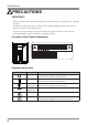
PRECAUTIONS PRECAUTIONS IMPORTANT! • This product has been adjusted specifically for use in the region to which it was originally shipped. If operated outside the region to which it was originally shipped, the product may not perform as stated in the specifications. • To ensure personal safety and proper maintenance, please read this section and the caution statements on the unit (refer to the figure below).
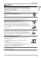
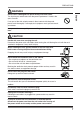
PRECAUTIONS WARNING English If the unit begins to emit smoke, smells like something is burning, or makes strange noises, disconnect all power connections immediately and contact your dealer for advice. Attempting to use a malfunctioning unit may result in fire, electric shock, or equipment damage. Do not open the cabinet or modify the unit. Opening the cabinet or modifying the unit may result in fire, electric shock, or burn. Refer all servicing to qualified service personnel.
PRECAUTIONS WARNING Use the enclosed power cord and connect to the standard power outlet of your country. Be sure to remain within the rated voltage of the power cord. Not doing so may result in fire or electric shock. Power supply: 100-120/200-240 Vac 50/60Hz To disconnect the power cord, grasp the plug firmly and pull. Tugging on the cord may damage and result in fire or electric shock. The equipment must be connected to a grounded main outlet. Not doing so may result in fire or electric shock.
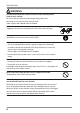
PRECAUTIONS WARNING English Do not touch a damaged LCD panel directly with bare hands. The liquid crystal which leaks from the panel is poisonous if it enters the eyes or mouth. If any part of the skin or body comes in direct contact with the panel, please wash thoroughly. If some physical symptoms result, please consult your doctor. Lamps contain mercury, dispose according to local, state or federal laws. CAUTION Handle with care when carrying the unit.
PRECAUTIONS Notice for this monitor The backlight of the LCD panel has a fixed life span. When the screen becomes dark or begins to flicker, please contact your dealer. The backlight of the LCD panel has a fixed life span. When the screen becomes dark or begins to flicker, please contact your dealer. Do not press on the panel or edge of the frame strongly, as this may result in damage to the screen. There will be prints left on the screen if the pressed image is dark or black.
1. Introduction 1. Introduction English Thank you for choosing an EIZO Monochrome Monitor. 1-1. Features • DVI (p.35) digital input (TMDS (p.35)) compliant • Horizontal scan frequency 31 - 135 kHz • Vertical scan frequency 19.0 - 61.0 Hz (VGA TEXT: 69 - 71 Hz, QSXGA: 19 - 51 Hz,) • Frame synchronous mode 49.0 - 51.0 Hz supported • Resolution 5M pixels (Portrait: 2048 × 2560 dots (H × V)) • CAL Switch function for selecting an optimal calibration mode (p. 23) • Selectable DICOM (p.
1. Introduction 1-3. Controls and Connectors Front ScreenManager® main menu Control Panel CAL Switch menu (1) (2) (3) (4) (5) 10 Mode Switch Enter Switch Displays the CAL Switch menu (p. 23). Displays the Adjustment menu, determines an item on the menu screen, and saves values adjusted Directing Switches*1 Chooses an adjustment item or increases/decreases adjusted (Left, Down, Up, Right) values for advanced adjustments using the Adjustment menu (p. 18) Power Switch Turns the power on or off.
1. Introduction Side / Rear English Power connector Main Power Switch (6) (7) (8) (9) (10) USB port (Up) USB port (Down) Input signal connectors Security lock slot*3 Stand*4 Connects the USB cable in order to use the provided software. Connects a peripheral USB device. DVI-D connector Complies with Kensington’s MicroSaver security system. Used to adjust the height and angle of the monitor screen. *3 Allows for connection of a security cable.
2. Installation 2. Installation 2-1. Before Connecting Before connecting your monitor to the PC, change the display screen settings resolution (p. 35) and frequency in accordance with the charts below. Tips • When your computer and monitor support VESA DDC, the appropriate resolution and the refresh rate are set just by plugging your display into the computer without any manual settings.
2. Installation 2-2. Cable Connection NOTE •Refer to the PC user's manual when connecting the monitor. •Before making a connection for non monochrome signal only specifications, the monitor must be configured. For more information, refer to “2-3. Environmental Settings” (p. 16). 1 2 Rotate the monitor ninety degrees counter-clockwise into the portrait position. Connect the signal cable to the DVI-D input connector on the rear of the monitor and to the video output connector on the PC.
2. Installation 3 4 Connect the power cord to the power connector on the rear of the monitor. Thread the power cord and signal cable through the cable holder on the rear of the monitor stand. NOTE •When threading the cables through the cable holder, lead them to the cable entrance side and pinch the projection to open the cable entrance.
2. Installation 7 Turn on the PC’s power. The image will appear. English If an image does not appear, refer to “7. Troubleshooting” (p. 29) for additional advice. When finished, turn off the PC and the monitor. Tips •Adjust the brightness of the screen depending on the brightness of your environment. •Be sure to take adequate rests. A 10-minute rest period each hour is suggested.
2. Installation 2-3. Environmental Settings The monitor may need to be set in some environment. If you install it for the first time or change environment, set the monitor. • Set the signal corresponding to make a connection for non monochrome signal only specifications. • Set the monitor orientation. If the monitor is in portrait position and make a connection for monochrome signal only specifications, no setting is required. NOTE •Refer to the manual of the graphics board.
2. Installation Select this option when using the Landscape orientation. Display Example A A Monitor Orientation Landscape English Portrait (SW) Select this option when using the Portrait orientation. Graphics board utility software is used to rotate the display image 90 degrees. Portrait (HW) Select this option when using the Portrait orientation. The monitor function is used to rotate the display image 90 degrees. 5 Restart the computer if the settings have been changed.
3. Adjustment and Settings 3. Adjustment and Settings 3-1. How to use the ScreenManager Screen adjustments and settings can be performed with the ScreenManager (OSD) and buttons of the monitor. Mode Switch Power Switch ScreenManager menu Directing Switches CAL Switch menu Left, Down, Up, Right Enter Switch Adjustment ScreenManager menu CAL Switch menu Switches *Adjustment Lock *Signal Selection Orientation Startup Enter Switch Mode Switch Description 3-2. ScreenManager menu (p. 19) 3-3.
3. Adjustment and Settings 3-2. ScreenManager menu English Using ScreenManager menu controls the screen adjustment and settings. Refer to the “Explanation” column in the following table for each detailed functions. Functions The following table shows all the ScreenManager’s adjustment and setting menus. Main menu Sub menu Setup Mode Preset Mode Brightness Reset DVI DMPM PowerManager Others Information Language Explanation Mode Preset Function -(P. 21) 4-1.
3. Adjustment and Settings How to use the ScreenManager ScreenManager Menu [Entering the ScreenManager] Touch the enter switch. [Making adjustments and settings] 1. Select the desired submenu icon with the directing switches and touch the enter switch. 2. Select the desired setting icon with the directing switches and touch the enter switch. 3. Make any required adjustments with the directing switches and touch the enter switch. [Exiting the ScreenManager] 1.
3. Adjustment and Settings Mode Preset Function - [How to set] 1. Select in the ScreenManager menu. 2. Set each mode to “On” or “Off”. NOTE • You cannot disable all modes. Set one or more modes to “On”. [How to cancel] 1. Select in the ScreenManager menu. 2. Set the mode that you wish to display to “On”. Power Saving Function The menu in the ScreenManager enables to set the power saving.
3. Adjustment and Settings Off Timer - The off timer function causes the monitor to turn off automatically after a predetermined amount of time has lapsed. This function was created to reduce the afterimages particular to LCD monitors, which appear when the screen is left on for long periods without use. [How to set] 1. Select in the ScreenManager menu. 2. Select “Enable” and touch the Right and Left directing switches to adjust the operating time (1 to 23 hours).
3. Adjustment and Settings 3-3. CAL Switch Function CAL Switch Modes Mode 1 - DICOM 2 - Native 3 - CAL * Description Used to display images in the DICOM mode (p. 35) Select this option to display images using the native characteristics of the monitor panel. Used for monitor calibration All modes can be calibrated independently. The mode name can also be changed using the calibration kit (p. 34). How to use the CAL Switch Function CAL Switch menu [Entering the CAL Switch menu] Touch the mode switch.
3. Adjustment and Settings 3-4. Adjustment Lock Function Use the “Adjustment Lock” function to prevent any accidental changes. Locked functions • Display, adjustment, and setting of the ScreenManager Unlocked function • Brightness adjustments to the CAL Switch mode • Selection of the CAL Switch mode with the mode switch [How to lock] 1. Turn off the monitor power by touching the power switch. 2. Touch the power switch while touching the enter switch. [How to unlock] 1.
4. Brightness Adjustment and Image Adjustment 4-1. Brightness Adjustment The brightness of the entire screen can be set to a desired level. [How to adjust] 1. Select in the ScreenManager menu. 2. Make adjustments with the Left and Right directing switches. The Left directing switch makes the screen darker, and the Right directing switch makes it brighter. NOTE • Selecting in the menu resets the brightness of the selected CAL Switch mode to the factory default setting.
5. Making use of USB (Universal Serial Bus) 5. Making use of USB (Universal Serial Bus) This monitor provides a hub which supports the USB standard. When connecting to a USB compliant PC or another hub, the monitor functions as a hub to which the USB compliant peripherals can be easily connected. Required system environment • PC equipped with USB ports or another USB hub connected to the USB compliant PC • Windows 2000/XP/Vista // Mac OS 9.2.2 and Mac OS X 10.
5. Making use of USB (Universal Serial Bus) 3 After setting up, the monitor’s USB hub is available for connecting USB compliant peripherals to the downstream ports of the monitor. English Connecting Examples Monitor PC Mouse Keyboard Downstream ports: Connect the cables from USB compliant peripherals such as a mouse, keyboard, etc.
6. Attaching an Arm 6. Attaching an Arm The LCD monitor can be used with an arm by removing the tilt stand and attaching the arm stand to the LCD monitor. NOTE • If you will use the arm or stand of other manufacturers, confirm the followings to the manufacturers before selecting.
7. Troubleshooting 7. Troubleshooting • No picture problems • Imaging problems See No.1 ~ No.2 See No.3 ~ No.6 • Other problems • USB problems English If a problem persists even after applying the suggested remedies, contact an EIZO dealer. See No.7 ~ No.9 See No.10 Problems 1. No picture Indicator status: Off Indicator status: Green Indicator status: Orange 2. One of the error messages shown below remains on the screen for 40 second. • The message appears when the signal is not input.
7. Troubleshooting Problems Points to check with possible solutions 5. The screen has defective pixels (e.g. slightly light or dark). 6. Interference patterns or pressure marks remain on the screen. 7. The ScreenManager main menu does not operate. • This is due to LCD panel characteristics and is not a failure. •Leave the monitor with a white or black screen. The symptom may disappear. • Make sure that the adjustment lock is off (p. 24). • Make sure the control panel switches are not wet or soiled.
8. Cleaning 8. Cleaning English Periodic cleaning is recommended to keep the monitor looking new and to prolong its operation lifetime. NOTE • Never use thinner, benzene, alcohol, abrasive cleaners, or other strong solvents, as these may cause damage to the cabinet or LCD panel. Cabinet To remove stains, wipe the cabinet with a soft, lightly moistened cloth using a mild detergent. Do not spray wax or cleaner directly into the cabinet. (For details, refer to the manual of the PC.
9. Specifications 9. Specifications LCD Panel 54cm(21.3 inch), TFT Monochrome LDC panel Surface treatment: Anti-Glare Hard Coating GS520-CL Surface hardness: 2H Response Time: 50ms GS520-BLG 54cm(21.3 inch), TFT Monochrome LDC panel GS520-CLG Surface treatment: Hard Coating Surface hardness: 3H Response Time: 50ms Viewing Angle Horizontal:170°, Vertical: 170° (CR 10 or more) Dot Pitch 0.
9. Specifications Dimensions 24(0.94) 82(3.23)Adjustable height 24(0.94) 28(1.1) 0° English mm (inches) TILT4 388(15.3) 340(13.4) 173(6.3) 95(3.74) 166(6.5) 168(6.6) 272.5(10.7) 35° SWIVEL 208.5(8.2) 311(12.2) 15(0.59) 240(9.4) 325(12.8) 8(0.31) 28(1.1) 78.5(3.09) 142(5.6) 32.5(1.28) 512.5(20.2) 466.5(18.4) 424(16.7) 480(18.9) 61.5(2.42) ° 88(3.
9. Specifications Network QC Management EIZO “RadiNET Pro” Ver.3.0.2 or later Software Cleaning Kit Signal Cable EIZO “RadiNET Pro Lite” Ver.3.0.2 or later EIZO “ScreenCleaner” DD200DL-BK Pin Assignment •DVI-D Connector 1 2 3 4 5 6 7 8 9 10 11 12 13 14 15 16 17 18 19 20 21 22 23 24 Pin No. Signal Pin No. Signal Pin No. Signal 1 2 3 4 5 6 7 T.M.D.S. Data2T.M.D.S. Data2+ T.M.D.S. Data2/4 Shield T.M.D.S. Data 4T.M.D.S. Data 4+ DDC Clock (SCL) DDC Data (SDA) 9 10 11 12 13 14 15 T.M.D.S. Data1T.M.
10. Glossary 10. Glossary The DICOM standard was developed by the American College of Radiology and the National Electrical Manufacturer’s Association of the USA. The DICOM compatible device connection enables to transfer the medical image and information. The DICOM, Part 14 document defines the digital, grayscale medical image display. DVI(Digital Visual Interface) A digital flat panel interface. DVI can transmit digital data from the PC directly without loss with the signal transition method “TMDS”.
EMC Information CAUTION The RadiForce series require special precautions regarding EMC and need to be installed, put into service and used according to the following information. Do not use any cables other than the cables that provided or specified by us. Using other cables may cause the increase of emission or decrease of immunity. Do not put any portable and mobile RF communications equipment close to the RadiForce series. Doing so may affect the RadiForce series.
Immunity test EN60601 test level Compliance level Electromagnetic environment guidance Conducted RF EN61000-4-6 3Vrms 150kHz to 80MHz 3Vrms 150kHz to 80MHz Portable and mobile RF communications equipment should be used no closer to any part of the RadiForce series, including cables, than the recommended separation distance calculated from the equation applicable to the frequency of the transmitter. Recommended Separation distance Radiated RF EN61000-4-3 3Vrms 80MHz to 2.5GHz 3Vrms 80MHz to 2.
Hinweise zur Auswahl des richtigen Schwenkarms für Ihren Monitor Dieser Monitor ist für Bildschirmarbeitsplätze vorgesehen. Wenn nicht der zum Standardzubehör gehörige Schwenkarm verwendet wird, muss statt dessen ein geeigneter anderer Schwenkarm installiert werden.
EIZO NANAO CORPORATION 153 Shimokashiwano, Hakusan, Ishikawa 924-8566 Japan Phone: +81 76 277 6792 Fax:+81 76 277 6793 EIZO NANAO TECHNOLOGIES INC. 5710 Warland Drive, Cypress, CA 90630, U.S.A.