User’s Manual Color LCD Monitor
English SAFETY SYMBOLS This manual uses the safety symbols below. They denote critical information. Please read them carefully. WARNING Failure to abide by the information in a WARNING may result in serious injury and can be life threatening. CAUTION Failure to abide by the information in a CAUTION may result in moderate injury and/or property or product damage. Indicates a prohibited action. Indicates to ground for safety. Copyright© 2002 by EIZO NANAO CORPORATION. All rights reserved.
English TABLE OF CONTENTS PRECAUTIONS ................................................................................... 4 1. INTRODUCTION ..................................................................................... 9 1-1. Features....................................................................................................... 9 1-2. Package Contents ........................................................................................ 9 1-3. Controls & Connectors ........................
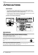
English PRECAUTIONS IMPORTANT! • This product has been adjusted specifically for use in the region to which it was originally shipped. If operated outside the region to which it was originally shipped, the product may not perform as stated in the specifications. • To ensure personal safety and proper maintenance, please read this section and the caution statements on the unit (refer to the figure below).
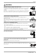
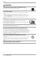
English WARNING Keep small objects or liquids away from the unit. Small objects accidentally falling through the ventilation slots into the cabinet or spillage into the cabinet may result in fire, electric shock, or equipment damage. If an object or liquid falls/spills into the cabinet, unplug the unit immediately. Have the unit checked by a qualified service engineer before using it again. Place the unit on a strong, stable surface.
English WARNING The equipment must be connected to a grounded main outlet. Not doing so may cause in fire or electric shock. Use the correct voltage. * Do not overload your power circuit, as this may result in fire or electric shock. * The unit is designed for use with a specific voltage only. Connection to another voltage than specified in this User’s Manual may cause fire, electric shock, or other damage. * Do not overload your power circuit, as this may result in fire or electric shock.
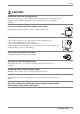
English CAUTION Handle with care when carrying the unit. Disconnect the power cord and cables when moving the unit. Moving the unit with the cord attached is dangerous. It may result in injury or equipment damage. When handling the unit, grip the bottom of the unit firmly with both hands ensuring the panel faces outward before lifting. Dropping the unit may result in injury or equipment damage. OK Do not block the ventilation slots on the cabinet.
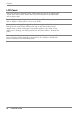
English LCD Panel The screen may have defective pixels. These pixels may appear as slightly light or dark area on the screen. This is due to the characteristics of the panel itself, and not the product. The backlight of the LCD panel has a fixed life span. When the screen becomes dark or begins to flicker, please contact your dealer. Do not press on the panel or edge of the frame strongly, as this will result in damage to the screen.
English 1. INTRODUCTION Thank you very much for choosing an EIZO Color Monitor. 1-1. Features • Dual inputs compliant • DVI (p. 44) Digital input (TMDS (p. 45)) compliant • Horizontal scanning frequency: 27 - 82 kHz (Digital input: 27 - 64 kHz) Vertical scanning frequency: 50 - 85 Hz Vertical (1280 x 1024 ~ 75 Hz) Vertical (Digital) of 60 Hz (VGA text: 70 Hz) Resolution: 1280 x 1024 • Smoothing function incorporated for the adjustment of an enlarged image. (p.
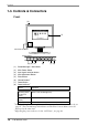
English 1-3.
English Rear (9) (10) (11) Bottom (12) (9) (10) (11) (12) (13) (14) (15) *3 *4 (13)(14) (15) *3 Height Adjustable Stand (Detachable) Power Terminal Covers for the Optional peripheral *4 Security Lock Slot DVI-I Input Connector x 2 (SIGNAL 1, SIGNAL 2) USB Port (4 Downstream) USB Port (1 Upstream) Power Connector The LCD monitor has the capability of the Portrait/Landscape display. (The panel pivots in the clockwise direction 90°.) For the Portrait display, use the software for the portrait.
English 2. CABLE CONNECTION 2-1. Before connecting Before connecting your monitor to the PC, change the display screen settings (resolution p. 45) and frequency) in accordance with the charts below. NOTE • When your computer and display support VESA DDC, the suitable resolution and the refresh rate are set by just plugging your display into the computer without any manual settings.
English 2-2. Connecting the signal cable NOTE • Be sure that the power switches of both the PC and the monitor are OFF. 1. Plug the signal cable into the connector at the rear of the monitor and the other end of the cable into the video connector on the PC. After connecting, secure the connection with the screw-in fasteners.
English 3. Lead the power cord and signal cable into the cable holder at rear of the monitor. NOTE • The cables are recommended to lead with slight sag for the smooth motion of the stand and the Portrait/Landscape display. Cable Holder 4. Plug the other end of the power cord into a power outlet. WARNING Use the enclosed power cord and connect to the standard power outlet of your country. Be sure to remain within the rated voltage of the power cord. Not doing so may cause in fire or electric shock.
English 2-3. Connecting two PCs to the monitor Two PCs can be connected to the monitor through the Signal 1 and the Signal 2 on the back of the monitor. Connecting Examples Signal 1 Signal 2 PC 1 PC 2 (Ex.1) Analog D-Sub mini 15 pin Signal Cable (FD-C16 enclosed) Signal Cable (FD-C04 enclosed) DVI Digital (Ex.2) Analog D-Sub mini 15 pin Signal Cable (FD-C16 enclosed) Signal Cable (FD-C16 optional) D-Sub mini 15 pin Analog (Ex.
English Selecting the active input The Input signal selection button on the front panel can be used to select either Signal 1 or Signal 2 as the active input at any time. Every time the button is pressed, the input changes. When switching the signal, the kind of the input signal (Signal1 or 2/Analog or Digital) is displayed for a few seconds on the right top corner of the screen.
English 3. ScreenManager 3-1. How to use the ScreenManager ScreenManager allows you to adjust screen performance though the main menu and select a fine contrast mode easily. [Ex.] Custom Main Menu Control Buttons Left, Down, Up, Right SIGNAL 1-2 Fine Contrast Menu AUTO ENTER Auto Adjustment Enter button button NOTE • Main Menu and Fine Contrast Menu cannot be activated at the same time. 1. Entering the ScreenManager Push the Enter button once to display the main menu of the ScreenManager. 2.
English 3-2. ScreenManager Adjustments and Settings. The following table shows all the ScreenManager’s adjustment and setting menus. “*” indicates adjustments of analog input only and “**” indicates digital input only. Main menu Sub menu Screen Reference Clock * Phase * 4-1. Screen Adjustment (p.22) Position Resolution Range Adjustment * Smoothing * Signal Filter *1 Color(Custom) Brightness 4-3. Color Adjustment (p.
English 3-3. Fine Contrast This function allows you to select the best suited mode for screen display. To select the Mode Directly pressing the left or right button allows you to select the best suited mode for screen display from 6 fine contrast modes; Text, Picture, Movie, sRGB, Custom and External. Color settings each mode can be adjusted by using the menu of the ScreenManager. NOTE • When the main menu of ScreenManager is displayed on the screen, the Fine Contrast Menu cannot be activated.
English 3-4. Useful Functions Adjustment Lock Use the “Adjustment Lock” function to prevent any accidental changes. Locked function • Auto adjustment button adjustments and settings in the ScreenManager. • Auto Adjustment Button Unlocked function • Selecting of the Fine Contrast mode by the control buttons. • Input signal selection button • To lock Switch off the monitor’s power by the power button on the front panel. Press on the Auto adjustment button while switching on the monitor’s power.
English EIZO Logo appearing function When switching on the power button on the front panel, the EIZO logo is displyed for a while. If you desire to display or undisplay this logo, use this function. (Default is logo appearing.) • To undisplay Switch off the monitor’s power by the power switch on the front panel, then hold down the Enter button once again and turn the power back on.
English 4. ADJUSTMENT 4-1. Screen Adjustment NOTE • Allow the LCD monitor to stabilize for at least 20 minutes before making image adjustments. When connecting the DVI cable for digital input, see page 25. Analog Input Screen adjustments for the LCD monitor should be used in suppressing screen flickering and also for adjusting the screen to its proper position. There is only one correct position for each display mode.
English NOTE • If the user’s operating system has no utility disk (e.g. OS/2), we recommend setting the desktop pattern to that as shown in the diagram on the following. 3. Adjust by using menu in the ScreenManager. (1) Vertical bars appear on the screen → Use the (p.44) adjustment. Select the “Clock” and eliminate the vertical bars by using the right and left of the control buttons.
English (3) The screen position is not incorrect. Use the adjustment. → The correct displayed position of the monitor is decided because the number and the position of the pixels are fixed. The adjustment moves the image to the correct position. Select and adjust the position of the upper left corner of the image by using the up, down, right and left buttons in order to align the screen.
English 4. Adjust the output signal range (Dynamic Range) of the signal. → Use the (p.45) of menu. This controls the level of output signal range to display the whole color gradation (256 colors). [Procedure] Push the Auto adjustment button on the front panel while displaying the menu to automatically adjust the range. The screen blanks for a moment and adjusts the color range to display the whole color gradation of the current output signal.
English 4-2. Displaying a low resolutions The lower resolutions are enlarged to full screen automatically. Using the function in the menu enables to change the screen size. 1. Enlarge the screen size when displaying a low resolution. → Select the . Select the in the others menu and select the screen size by using the up and down buttons. Menu Function Full Displays the picture on the screen in full, irrespective of the picture’s resolution.
English 3. Set the brightness of the black area surrounding the displayed image. → Set the . In the mode or mode, the outer area (border) is usually black. Select in the menu and adjust by using the right and left buttons. Border 4.
English 4-3. Color Adjustment Color settings of each Fine Contrast mode can be adjusted and saved by using the menu of the ScreenManager. In the analog input, perform the “Range Adjustment” (p.25) before making the color adjustments. During color adjustments, the Fine Contrast mode cannot be changed. Select the mode in advance by using the Fine Contrast Mode.
English Adjustment Contents Menu Function Descriptions Adjustable range Brightness To set the brightness of the screen 0 ∼ 100% Temperature (p.45) To set the color temperature 4,000 ∼ 10,000 K in 500 K increments (including 9,300 K). Default setting is off (normal white) NOTE • The values shown in the Kelvin are available only as a reference tool. • Setting the temperature under 4,000 K or over 10,000 K invalidates the color temperature setting. (The color temperature’s setting turns “OFF”.
English 4-4. Power-save Setup The menu in the ScreenManager enables to set the power-save setup. NOTE • Do your part to conserve energy, turn off the monitor when you are finished using it. Disconnecting the monitor from the power supply is recommended to save energy completely. • Even if the monitor is in a power saving mode, USB compliant devices function when they are connected to the monitor’s USB (both the upstream and the downstream ports).
English To set the power save with ScreenSaver (EIZO MPMS) software. [Procedure] (1) Set the PC’s appropriate ScreenSaver settings or blank the screen (totally black screen). (2) Select in the menu. [Power saving system] PC Operation Blank the screen (ScreenSaver or Macintosh Energy Saver) Monitor LED Operation Green Power saving Yellow Operate the mouse or keyboard to return to a normal screen. NOTE • EIZO MPMS should be used with Macintosh “EnergySaver”.
English 5. MAKING USE OF USB (Universal Serial Bus) This monitor provides a hub which supports the USB standard. When connecting to a USB compliant PC or another hub, the monitor functions as a hub to which the USB compliant peripherals can be easily connected. Required system environment • PC equipped with USB ports or another USB hub connected to the USB compliant PC • Windows 98/2000/XP // Mac OS 8.5.
English 3. After setting up, the monitor’s USB hub is available for connecting USB compliant peripherals to the downstream ports of the monitor. Connecting Examples Scanner Digital Camera Monitor PC Mouse Keyboard Printer Downstream Downstream ports: Connect the cables from USB compliant peripherals such as a mouse, keyboard, etc.
English 6. ATTACHING AN ARM STAND The LCD monitor can be used with an arm stand by removing the tilt stand and attaching the arm stand to the LCD monitor. NOTE • Use an arm stand that satisfies the followings. - When using the LCD monitor with an arm stand, the arm stand must be VESA approved: Use an arm stand with a 100 mm x 100 mm hole spacing on the arm mounting pad. Weight: Use an arm stand that is able to support an object weighting 13.5 kg (29.8 lbs.).
English 4. Attach an arm stand to the LCD monitor securely. Arm-stand M4 Mounting Screws: M4 x 15 (mm) BZn/Fe 6.
English 7. TROUBLESHOOTING If a problem persists even after applying the suggested remedies, contact an EIZO dealer. • No picture problems → See No.1 ~ No.2 • Imaging problems → See No.3 ~ No.14 • Other problems → See No.15 ~ No.19 • USB problems → See No.20 ~ No.21 Problems 1. No picture • Indicator status: Off • Indicator status: Green • Indicator status: Yellow • Indicator status: Slowly flashing Yellow • Indicator status: Flashing Yellow (twice for each) 2.
English Problems Points to check with possible solutions 3. Display position is incorrect. ! Adjust the image position using the (p.24) If the problem persists, use the graphics board’s utility software to change the display position if available. 4. Screen image is smaller or larger than the actual screen images. ! Adjust the resolution using the . (p.24) 5. Vertical bars of distortion appear. ! Decrease the vertical bars using the . (p.23) 6.
English Problems Points to check with possible solutions 11. Afterimages appear. ! When the screen image is changed after displaying the same image for a long period, an afterimage may appear. The “Afterimage” can be removed gradually by changing the displayed image. Use the “Off Timer” function and avoid keeping the screen on all the time. (p.20) 12. The screen has defective pixels (e.g. slightly light or dark). ! This is due to the characteristics of the panel itself and not the LCD product. 13.
English Problems Points to check with possible solutions 20. USB function cannot be setup. ! Check that the USB cable is correctly connected. ! Check that the PC and OS are USB compliant. (For verification of USB support, consult the manufacturer of each system.) ! Check the PC’s BIOS setting for USB. (For details, refer to the manual of the PC.) 21. PC is hung up. / The peripherals connected to the downstream ports do not operate. ! Check that the USB cable is correctly connected.
English 8. CLEANING Periodic cleaning is recommended to keep the monitor looking new and to prolong its operation lifetime. NOTE • Never use thinner, benzene, alcohol (ethanol, methanol, or isopropyl alcohol), abrasive cleaners, or other strong solvents, as these may cause damage to the cabinet or LCD panel. Cabinet To remove stains, wipe the cabinet with a soft, lightly moistened cloth using a mild detergent. Do not spray wax or cleaner directly into the cabinet.
English 9. SPECIFICATIONS LCD Panel 46 cm (18.1 inch), TFT color LCD panel with Anti-Glare Hard Coating, Viewing Angle: Horizontal: 170°, Vertical: 170° Image Formation Time: approx. 78 ms Dot Pitch 0.2805 mm Horizontal Scan Frequency 27 ∼ 82 kHz (Automatic) (Digital): 27 ~ 64 kHz Vertical Scan Frequency 50 Hz ∼ 85 Hz (Automatic) (1280 x 1024: 50 Hz ∼ 75 Hz) (Digital): 60Hz, (VGA TEXT : 70Hz) Resolution 1280 dots x 1024 lines Dot Clock (Max.
English Default settings Analog input Digital input Contrast 100% 100% Brightness 100% 100% Smoothing 3 Fine Contrast Mode Custom PowerManager VESA DPMS Screen Size Full Input Priority Signal 1 Menu Off Timer Disable Menu Settings Menu Size Normal Menu Off Timer 45 seconds Beep On Language English DVI DMPM Beeper settings Short beep ScreenManager item selected. ScreenManager parameter adjusted to minimum or maximum limit. Input signal selection button pressed.
English Pin Assignment DVI-I Connector 1 2 3 4 5 6 7 8 9 10 11 12 13 14 15 16 17 18 19 20 21 22 23 24 C1 C2 C3 C4 C5 Pin No. Signal Pin No. Signal Pin No.
English 10. GLOSSARY Afterimage The Afterimage is particular to LCD monitors when the monitor screen is left on for a long period without use. The “Afterimage” can be removed gradually by changing the displayed image. Clock With the analog input signal display, the analog signal is converted to a digital signal by the LCD circuitry. To convert the signal correctly, the LCD monitor needs to produce the same number clock pulse as the dot clock of the graphics system.
English Phase The phase adjustment decides the sampling timing point for converting the analog input signal to a digital signal. Adjusting the phase after the clock adjustment will produce a clear screen. Range Adjustment The Range Adjustment controls the level of output signal range to display the whole color gradation. Resolution The LCD panel consists of a fixed number of pixel elements which are illuminated to form the screen image.
APPENDIX/ANHANG/ANNEXE Preset Timing Chart for Analog input Timing-Übersichten für Analog Eingang Synchronisation des Signaux pour Analog numerique Based on the signal diagram shown below 25 factory presets have been registered in the monitor's microprocessor. Der integrierte Mikroprozessor des Monitors unterstützt 25 werkseitige Standardeinstellungen (siehe hierzu die nachfolgenden Diagramme).
Mode Dot Clock Sync Polarity MHz H kHz V Hz 25.175 Nega. Nega. 31.469 59.940 28.322 Nega. Posi. 31.468 70.087 30.24 Posi. Posi. 35.00 66.67 57.28 Posi. Posi. 49.73 74.55 100.0 Posi. Posi. 68.68 75.06 126.2 Posi. Posi. 74.76 74.76 31.5 Nega. Nega. 37.86 72.81 31.5 Nega. Nega. 37.50 75.00 36.0 Nega. Nega. 43.27 85.01 36.0 Posi. Posi. 35.16 56.25 40.0 Posi. Posi. 37.88 60.32 50.0 Posi. Posi. 48.08 72.19 49.5 Posi. Posi. 46.88 75.00 56.25 Posi.
C: Back Porch H µs/ Dot 1.589/ 40 1.907/ 54 3.175/ 96 3.911/ 224 1.440/ 144 1.838/ 232 3.810/ 120 3.810/ 120 2.222/ 80 3.556/ 128 2.200/ 88 1.280/ 64 3.232/ 160 2.702/ 152 2.462/ 160 19.20/ 144 2.235/ 176 2.201/ 208 2.370/ 256 2.889/ 312 2.296/ 248 1.837/ 248 V ms/ Line 0.794/ 25 1.111/ 35 1.114/ 39 0.784/ 39 0.568/ 39 0.482/ 36 0.528/ 20 0.427/ 16 0.578/ 25 0.626/ 22 0.607/ 23 0.478/ 23 0.448/ 21 0.503/ 27 0.600/ 29 0.513/ 29 0.466/ 28 0.524/ 36 0.474/ 32 0.600/ 36 0.594/ 38 0.
Mode Dot Clock Sync Polarity MHz H Workstation 1152 × 900 Workstation 1152 × 900 Workstation 1280 × 1024 iv V Frequencies H kHz 61.974 V Hz 66.141 94.2 Composite, Nega. 107.50 Composite, Nega. 71.858 76.202 117.0 Composite, Nega. 71.691 67.189 APPENDIX/ANHANG/ANNEXE A: Front Porch H µs/Dot 0.425/ 40 0.223/ 24 0.205/ 24 B: Sync Period V ms/Line H µs/ Dot V ms/ Line 0.032/ 1.359/ 0.065/ 2 128 4 0.028/ 1.265/ 0.111/ 2 136 8 0.028/ 0.957/ 0.
C: Back Porch H µs/ Dot 2.123/ 200 1.712/ 184 1.846/ 216 V ms/ Line 0.500/ 31 0.459/ 33 0.460/ 33 D: Blanking Period H µs/ Dot 3.907/ 368 3.200/ 344 3.009/ 352 V ms/ Line 0.597/ 37 0.598/ 43 0.600/ 43 E: Display Period H µs/ Dot 12.229/ 1152 10.716/ 1152 10.940/ 1280 V ms/ Line 14.522/ 900 12.525/ 900 14.283/ 1024 F: Total Cycle H µs/ Dot 16.136/ 1520 13.916/ 1496 13.949/ 1632 V ms/ Line 15.119/ 937 13.123/ 943 14.
[Applicable to gray (standard color version only).] Congratulations! You have just purchased a TCO’99 approved and labelled product! Your choice has provided you with a product developed for professional use. Your purchase has also contributed to reducing the burden on the environment and also to the further development of environmentally adapted electronics products.
Environmental Requirements Flame retardants Flame retardants are present in printed circuit boards, cables, wires, casings and housings. Their purpose is to prevent, or at least to delay the spread of fire. Up to 30% of the plastic in a computer casing can consist of flame retardant substances. Most flame retardants contain bromine or chloride, and those flame retardants are chemically related to another group of environmental toxins, PCBs.
For U.S.A, Canada, etc. (rated 100-120 Vac) Only FCC Declaration of Conformity We, the Responsible Party EIZO NANAO TECHNOLOGIES INC. 5710 Warland Drive, Cypress, CA 90630 Phone: (562) 431-5011 declare that the product Trade name: EIZO Model: FlexScan L685 is in conformity with Part 15 of the FCC Rules.
Hinweis zur Ergonomie : Dieser Monitor erfüllt die Anforderungen an die Ergonomie nach EK1-ITB 2000 mit dem Videosignal, 1280 Punkte × 1024 Zeilen, RGB analog, 0,7 Vp-p und mindestens 75,0 Hz Bildwiederholfrequenz, non interlaced. Weiterhin wird aus ergonomischen Gründen empfohlen, die Grundfarbe Blau nicht auf dunklem Untergrund zu verwenden (schlechte Erkennbarkeit, Augenbelastung bei zu geringem Zeichenkontrast.