User’s Manual Color LCD Monitor It shall be assured that the final system is in compliance to IEC60601-1-1 requirements.
English SAFETY SYMBOLS This manual uses the safety symbols below. They denote critical information. Please read them carefully. WARNING Failure to abide by the information in a WARNING may result in serious injury and can be life threatening. Indicates a prohibited action. Indicates to ground for safety. • Power supplied equipment can emit electromagnetic waves, that could influence, limit or result in malfunction of the monitor.
English TABLE OF CONTENTS PRECAUTIONS ................................................................................... 4 1. INTRODUCTION ..................................................................................... 9 1-1. Features ........................................................................................................9 1-2. Package Contents..........................................................................................9 1-3. Controls & Connectors .......................
English PRECAUTIONS IMPORTANT! • This product has been adjusted specifically for use in the region to which it was originally shipped. If operated outside the region to which it was originally shipped, the product may not perform as stated in the specifications. • To ensure personal safety and proper maintenance, please read this section and the caution statements on the unit (refer to the figure below).
English Small objects accidentally falling through the ventilation slots into the cabinet or spillage into the cabinet may result in fire, electric shock, or equipment damage.
English WARNING Use the enclosed power cord and connect to the standard power outlet of your country. Be sure to remain within the rated voltage of the power cord. Not doing so may result in fire or electric shock. To disconnect the power cord, grasp the plug firmly and pull. Tugging on the cord may damage and result in fire or electric shock. The equipment must be connected to a grounded main outlet. Not doing so may result in fire or electric shock. Use the correct voltage.
English WARNING Do not touch a damaged LCD panel directly with bare hands. The liquid crystal which leaks from the panel is poisonous if it enters the eyes or mouth. If any part of the skin or body comes in direct contact with the panel, please wash thoroughly. If some physical symptoms result, please consult your doctor. Follow local regulation or laws for safe disposal. The backlight of the LCD panel contains mercury.
English LCD Panel In order to suppress the luminosity change by long-term use and to maintain the stable luminosity, please use the monitor with the brightness below 150 cd/m2 (BRIGHTNESS approximately 85 %). The screen may have defective pixels. These pixels may appear as slightly light or dark area on the screen. This is due to the characteristics of the panel itself, and not the product. The backlight of the LCD panel has a fixed life span.
English 1. INTRODUCTION Thank you very much for choosing an EIZO Color Monitor. 1-1. Features • Dual inputs compliant (DVI-I and D-Sub mini 15 pin connecters) • DVI (p. 49) Digital input (TMDS (p.
English 1-3. Controls & Connectors Front 10 1.
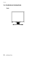
English Rear (9) (11)(12)(13) (10) (15) 1.
English 2. CABLE CONNECTION 2-1. Before Connecting Before connecting your monitor to the PC, change the display screen settings (resolution p. 50) and frequency) in accordance with the charts below. NOTE • When your computer and display support VESA DDC, the suitable resolution and the refresh rate are set by just plugging your display into the computer without any manual settings.
English 2-2. Connecting the signal cable (For the computer employing D-Sub or DVI connector) NOTE • Be sure that the power switches of both the PC and the monitor are OFF. 1. Plug the signal cable into the connector at the rear of the monitor and the other end of the cable into the video connector on the PC. After connecting, secure the connection with the screw-in fasteners.
English Digital Input Signal Cable Signal Cable (FD-C39 enclosed) Connector Video Output Connector / DVI Input Connector (monitor) / DVI PC • Digital graphics board • Power Mac G4(DVI) 2. Plug the power cord into the power connector on the rear of the monitor. 3. Lead the power cord and signal cable into the cable holder at rear of the monitor. NOTE • When housing the cables into the cable holder, lead them to the cable entrance side and pinch the projection to open the cable entrance.
English WARNING The equipment must be connected to a grounded main outlet. Not doing so may result in fire or electric shock. Not doing so may result in fire or electric shock. 5. Turn on the monitor’s Power Button and then switch on the PC’s power. The monitor’s power indicator will light up (blue). If an image does not appear, refer to the “7. TROUBLESHOOTING” (p.40) for advice. Whenever finished, turn off the PC and the monitor.
English 2-3. Connecting the signal cable (For the computer employing ADC) NOTE • Be sure that the power switches of both the PC and the monitor are OFF. 1. Plug the signal cable into the connector at the rear of the monitor and the other end of the cable into the video connector on the PC. After connecting, secure the connection with the screw-in fasteners.
English 3. Lead the power cord and signal cable into the cable holder at rear of the monitor. NOTE • When housing the cables into the cable holder, lead them to the cable entrance side and pinch the projection to open the cable entrance. • The cables are recommended to lead with slight sag for the smooth motion of the stand and the Portrait/Landscape display. Cable Holder Projection Cable Entrance 4. Plug the other end of the cord into a power outlet.
English 5. Press the power button while pressing the Input Signal Selection button. The Input Selection menu is appeared on the screen. Enter Button Input Signal Selection Button 6. Power Button Power Indicator Control Buttons (Up, Down, Left, Right) Change SIGNAL 1 (DVI-I Connector) in the Input Selection menu to “ADC”. Press Enter button to complete the setting and the menu closes. 7. Switch on the PC's power. The monitor’s power indicator will light up (blue).
English 2-4. Connecting Two PCs to the Monitor Two PCs can be connected to the monitor through the Signal 1 and the Signal 2 on the back of the monitor. Connecting Examples DVI-I Input Connector (SIGNAL 1) D-Sub 15 pin mini Input Connector (SIGNAL 2) PC 1 PC 2 (Ex.1) Analog D-Sub mini 15 pin Signal Cable (FD-C16 enclosed) Signal Cable (MD-C87 enclosed) D-Sub mini 15 pin Analog (Ex.
English The Priority Input Signal This function is used to select which PC will have priority to control the monitor when utilizing two PCs. The monitor constantly checks the input signals and switches automatically in accordance with the “Input Priority” setting (see table below). Once a priority is set, whenever a change of signal is detected at the selected input, the monitor will switch the input to that signal.
English 3. ScreenManager 3-1. How to use the ScreenManager ScreenManager allows you to adjust screen performance though the main menu and select a FineContrast mode easily. [Ex.] Custom Main Menu Control Buttons Left, Down, Up, Right SIGNAL 1-2 FineContrast Menu AUTO ENTER Auto Adjustment Enter Button Button NOTE • Main Menu and FineContrast Menu cannot be activated at the same time. 1. Entering the ScreenManager Press the Enter Button once to display the main menu of the ScreenManager. 2.
English 3-2. ScreenManager Adjustments and Settings. The following table shows all the ScreenManager’s adjustment and setting menus. “*” indicates adjustments of analog input only and “**” indicates digital input only. Main menu Sub menu Screen Reference Clock * Phase * 4-1. Screen Adjustment (p.26) Position Resolution Range Adjustment * Smoothing * Signal Filter Color (Custom) *1 Brightness 4-3. Color Adjustment (p.
English 3-3. FineContrast This function allows you to select the best suited mode for screen display. To select the Mode Directly pressing the Left or Right Button allows you to select the best suited mode for screen display from 6 FineContrast modes; “Custom”, “sRGB”, “CAL”, “Text”, “DICOM-CL” and “DICOM-BL”. Color settings each mode can be adjusted by using the menu of the ScreenManager.
English 3-4. Useful Functions Adjustment Lock Use the “Adjustment Lock” function to prevent any accidental changes. Locked function • Adjustments and settings in the ScreenManager. • Auto Adjustment Button Unlocked function • Selecting of the FineContrast mode by the Control Buttons. • Input Signal Selection Button [How to lock] (1) Switch off the monitor’s power by the power button on the control panel. (2) Press on the Auto adjustment button while switching on the monitor’s power.
English Power Indicator Setting Light off the power indicator. This function is available for the multiple panels settings. [Procedure] (1) Select in the ScreenManager menu. (2) Select “Disable”. Sync Switch Setting Correct the greenish screen caused by the input signal timing. [To set] (1) Switch off the monitor’s power by the main power switch. (2) Press on the down button while switching on the monitor’s main power switch again. (3) The Sync Switch setting has been changed.
English 4. ADJUSTMENT 4-1. Screen Adjustment NOTE • Allow the LCD monitor to stabilize for at least 20 minutes before making image adjustments. When connecting the DVI cable for digital input, see page 29. Analog Input Screen adjustments for the LCD monitor should be used in suppressing screen flickering and also for adjusting the screen to its proper position. There is only one correct position for each display mode.
English NOTE • If the user’s operating system has no utility disk (e.g. OS/2), we recommend setting the desktop pattern to that as shown in the diagram on the following. 3. Adjust by using menu in the ScreenManager. (1) Vertical bars appear on the screen → Use the (p.49) adjustment. Select the “Clock” and eliminate the vertical bars by using the Right and Left of the Control Buttons.
English (3) The screen position is not incorrect. → Use the adjustment. The correct displayed position of the monitor is decided because the number and the position of the pixels are fixed. The adjustment moves the image to the correct position. Select and adjust the position of the upper left corner of the image by using the Up, Down, Right and Left Buttons in order to align the screen.
English 4. Adjust the output signal range (Dynamic Range) of the signal. Use the (p.50) of menu. → This controls the level of output signal range to display the whole color gradation (256 colors). [Procedure] Press the Auto Adjustment Button on the control panel while displaying the menu to automatically adjust the range. The screen blanks for a moment and adjusts the color range to display the whole color gradation of the current output signal.
English 4-2. Displaying Low Resolutions The lower resolutions are enlarged to full screen automatically. Using the function in the menu enables to change the screen size. 1. Enlarge the screen size when displaying a low resolution. → Select the . Select the in the others menu and select the screen size by using the Up and Down Buttons. Menu Function Full Displays the picture on the screen in full, irrespective of the picture’s resolution.
English 3. Set the brightness of the black area surrounding the displayed image. Set the . → In the mode or mode, the outer area (border) is usually black. Select in the menu and adjust by using the Right and Left Buttons. Border 4.
English 4-3. Color Adjustment Color settings of each FineContrast mode can be adjusted and saved by using the menu of the ScreenManager. In the analog input, perform the “Range Adjustment” (p.29) before making the color adjustments. During color adjustments, the FineContrast mode cannot be changed. Select the mode in advance by using the FineContrast Mode. Adjustment items The adjustable items and displayed icons on the ScreenManager depend on the selected FineContrast mode.
English Adjustment Contents Menu Function Descriptions Adjustable Range Brightness To set the brightness of the screen 0 ∼ 130% Temperature (p.50) To set the color temperature 4,000 ∼ 15,000 K in 500 K increments (including 9,300 K). ‘Off’ is original color of LCD panel (normal white). NOTE • The values shown in the Kelvin are available only as a reference tool. • Setting the temperature under 4,000 K or over 15,000 K invalidates the color temperature setting.
English Unlock Function after Calibration The calibration is available when using the specified optional calibration kit. (p.46) After the calibration in FineContrast CAL mode, the brightness adjustment function is automatically locked. Unlock function is available by using ScreenManager. How to unlock (1) Select the of menu. (2) Select “Unlock”. NOTE • Performing the of , locked function is also unlocked. • After the unlock, the is disabled. 34 4.
English 4-4. Power-save Setup The menu in the ScreenManager enables to set the power-save setup. NOTE • Do your part to conserve energy, turn off the monitor when you are finished using it. Disconnecting the monitor from the power supply is recommended to save energy completely. • Even if the monitor is in a power saving mode, USB compliant devices function when they are connected to the monitor’s USB (both the upstream and the downstream ports).
English 5. MAKING USE OF USB (Universal Serial Bus) This monitor provides a hub which supports the USB standard. When connecting to a USB compliant PC or another hub, the monitor functions as a hub to which the USB compliant peripherals can be easily connected. Required system environment • PC equipped with USB ports or another USB hub connected to the USB compliant PC • Windows 98/2000/Me/XP // Mac OS 8.5.
English 3. After setting up, the monitor’s USB hub is available for connecting USB compliant peripherals to the downstream ports of the monitor. Connecting Examples 5.
English 6. ATTACHING AN ARM The LCD monitor can be used with an arm by removing the tilt stand and attaching the arm or stand to the LCD monitor. NOTE • If you will use the arm or stand of other manufacturers, confirm the followings to the manufacturers before selecting.
English 4. Attach an arm stand to the LCD monitor securely. Arm-stand M4 Mounting Screws: M4 x 15 (mm) BZn/Fe 6.
English 7. TROUBLESHOOTING If a problem persists even after applying the suggested remedies, contact an EIZO dealer. • No picture problems → See No.1 ~ No.2 • Imaging problems → See No.3 ~ No.14 • Other problems → See No.15 ~ No.20 • USB problems → See No.21 ~ No.22 Problems 1. No picture • Indicator status: Off • Indicator status: Blue • Indicator status: Yellow • Indicator status: Slowly flashing Yellow 2.
English Problems Points to check with possible solutions 3. Display position is incorrect. Adjust the image position using the (p.28) If the problem persists, use the graphics board’s utility software to change the display position if available. 4. Screen image is smaller or larger than the actual screen images. Adjust the resolution using the . (p.28) 5. Vertical bars of distortion appear. Decrease the vertical bars using the . (p.27) 6.
English Problems Points to check with possible solutions 10. The screen is too bright or too dark. Adjust the (The backlight of the LCD monitor has a fixed life span. When the screen becomes dark or begins to flicker, please contact your dealer.) Some input signal timing causes greenish screen. Change the Sync Switch setting. (p.25). 11. Afterimages appear. When the screen image is changed after displaying the same image for a long period, an afterimage may appear.
English Problems Points to check with possible solutions 21. PC is hung up. / The peripherals connected to the downstream ports do not operate. Check that the USB cable is correctly connected. Check the downstream ports by connecting the peripherals to other downstream ports. If the problem is solved by doing this, contact an EIZO dealer. (For details, refer to the manual of the PC.) Try executing the following method.
English 8. CLEANING Periodic cleaning is recommended to keep the monitor looking new and to prolong its operation lifetime. NOTE • Never use thinner, benzene, alcohol (ethanol, methanol, or isopropyl alcohol), abrasive cleaners, or other strong solvents, as these may cause damage to the cabinet or LCD panel. Cabinet To remove stains, wipe the cabinet with a soft, lightly moistened cloth using a mild detergent. Do not spray wax or cleaner directly into the cabinet.
English 9. SPECIFICATIONS LCD Panel 54 cm (21.3 inch), TFT color LCD panel with Anti-Glare Hard Coating, Viewing Angle: Horizontal: 170°, Vertical: 170° (CR≥10) Dot Pitch 0.270 mm Horizontal Scan Frequency Analog: 31 ∼ 94 kHz (Automatic) Digital: 31 ~ 76 kHz Vertical Scan Frequency Analog: 49 ∼ 86 Hz (Automatic) (1600 x 1200: 49 ∼ 76 Hz) Digital: 59 ~ 61 Hz, (VGA TEXT: 69 ~ 71 Hz) Resolution 2M pixels Landscape: 1600 dots × 1200 lines Portrait: 1200 dots × 1600 lines Dot Clock (Max.
English Certifications and Standards TÜV Rheinland /GM, CB, NRTL/C-TÜV, CE (93/42/EEC), FCC-B Classification of Equipment Type of protection against electric shock: Class I EMC class: EN60601-1-2: 2001 Group 1 Class B Classification of medical device (MDD 93/42/EEC): Class I Default Settings Analog input FineContrast Mode Custom Brightness 100% Temperature 7500K Smoothing 3 PowerManager VESA DPMS Screen Size Full Input Priority 1 Off Timer Disable Menu Settings Menu Size Normal Menu
English Dimensions 3.0(0.12) 472(18.6) 434(17.1) 3.0(0.12) 43(1.69) 35 34(1.34) 208.5(8.21) 35 SWIVEL 9.
English USB Port Upstream Series B 48 Downstream Series A 9. SPECIFICATIONS No.
English 10. GLOSSARY Afterimage The Afterimage is particular to LCD monitors when the monitor screen is left on for a long period without use. The “Afterimage” can be removed gradually by changing the displayed image. Clock With the analog input signal display, the analog signal is converted to a digital signal by the LCD circuitry. To convert the signal correctly, the LCD monitor needs to produce the same number clock pulse as the dot clock of the graphics system.
English Gamma Generally, the relationship that the light intensity values of a monitor change nonlinearly to the input signal level is called “Gamma Characteristic”. On the monitor, low gamma values display the whitish images and high gamma values display the high contrast images. Phase The phase adjustment decides the sampling timing point for converting the analog input signal to a digital signal. Adjusting the phase after the clock adjustment will produce a clear screen.
APPENDIX/ANHANG/ANNEXE Preset Timing Chart for Analog input Timing-Übersichten für Analog Eingang Synchronisation des Signaux pour Analog numerique Based on the signal diagram shown below 30 factory presets have been registered in the monitor's microprocessor. Der integrierte Mikroprozessor des Monitors unterstützt 30 werkseitige Standardeinstellungen (siehe hierzu die nachfolgenden Diagramme).
Mode VESA 1152 x 864 @ 75 Hz VESA 1280 x 960 @ 60 Hz VESA 1280 × 1024 @ 60 Hz VESA 1280 × 1024 @ 75 Hz VESA 1280 × 1024 @ 85 Hz VESA 1600 × 1200 @ 60 Hz VESA 1600 × 1200 @ 65 Hz VESA 1600 × 1200 @ 70 Hz VESA 1600 × 1200 @ 75 Hz SUN WS 1152 × 900 @ 66 Hz SUN WS 1152 × 900 @ 76 Hz SUN WS 1280 × 1024 @ 67 Hz ii Sync Polarity H V Posi. Posi. Frequencies H kHz V Hz 67.50 75.00 108.0 Posi. Posi. 60.00 60.00 108.0 Posi. Posi. 63.98 60.02 135.0 Posi. Posi. 79.98 75.03 157.5 Posi. Posi. 91.
For U.S.A, Canada, etc. (rated 100-120 Vac) Only FCC Declaration of Conformity We, the Responsible Party EIZO NANAO TECHNOLOGIES INC. 5710 Warland Drive, Cypress, CA 90630 Phone: (562) 431-5011 declare that the product Trade name: EIZO Model: RadiForce R22 is in conformity with Part 15 of the FCC Rules.
Recycle Auskunft Die Rücknahme dieses Produktes nach Nutzungsende übernimmt EIZO in Deutschland zusammen mit dem Partner MIREC GmbH & Co. KG. Dort werden die Geräte in ihre Bestandteile zerlegt, die dann der Wiederverwertung zugeführt werden. Um einen Abholtermin zu vereinbaren und die aktuellen Kosten zu erfahren, benutzen Sie bitte folgende Rufnummer: 02153-73 35 00. Weitere Informationen finden Sie auch unter der InternetAdresse: www.eizo.de.