Important Please read PRECAUTIONS and this User’s Manual carefully to familiarize yourself with safe and effective usage procedures. Please retain this manual for future reference.
Copyright© 2007 Tech Source, Inc. Copyright© 2007 EIZO NANAO CORPORATION No part of this manual may be reproduced, stored in a retrieval system, or transmitted, in any form or by any means, electronic, mechanical, or otherwise, without the prior written permission of Tech Source, Inc. and EIZO NANAO CORPORATION. Tech Source, Inc. and EIZO NANAO CORPORATION are under no obligation to hold any submitted material or information confidential unless prior arrangements are made pursuant to Tech Source, Inc.
Contents 1 1.1 1.2 1.3 1.4 1.5 Overview............................................................................................................................... 6 Layout of this Manual............................................................................................................. 7 Warnings and Safety Notes ................................................................................................... 8 Packaging .......................................................................
5.1 5.2 5.3 5.4 5.5 5.6 5.7 5.8 5.9 5.10 Technical Data ................................................................................................................... 54 Display Module .................................................................................................................... 54 Power Supply....................................................................................................................... 54 Operating Conditions ...........................................
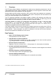
1 Overview The TFT Monitor Raptor SQ2801 was developed to meet the very demanding requirements in the Air Traffic Management where system availability and reliability is crucial. Ergonomic criteria have been addressed to ensure high acceptance from the operators. Reduced depth and lower weight compared to CRT monitors allow easy installation into workstation consoles of air traffic control rooms. Considerably lower power consumption and heat emissions are some of the other advantages over CRT based units.
1.1 Layout of this Manual This manual was created to assist system integrators and operators during installation and operation of the LCD TFT Monitor Raptor SQ2801. The layout is intended to allow even inexperienced users to install and set-up the monitor.
1.2 Warnings and Safety Notes For information about warnings and safety notes, refer to PRECATUIONS supplied with this manual.
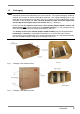
1.3 Packaging NOTE To avoid permanent damage, great care should be taken to ensure that the monitor is adequately packed and transported in the correct manner. The original packaging should be retained and re-used for future transportation purposes. The original packaging has a red label with two arrows and text “hier oben” (see Fig. 1 and Fig. 2), which indicates the correct orientation of the package (i.e.
1.4 Instructions for Handling Components Susceptible to Electrostatic Shocks Most of the assemblies within the LCD monitor Raptor SQ2801 contain components which can be permanently damaged or destroyed by electrostatic discharge. Such resulting damage may or may not result in total failure of the components or modules affected.
2 General Installation Preparation for installing the LCD monitor includes following steps: • Removal of all packaging materials • Checking of components for damage • Comparison of components received with those listed on the delivery note • Connection to the computer system and power supply • System integration under consideration of technical and ergonomic aspects 2.
2.2 Installing the Monitor The Raptor SQ2801 is currently offered in two versions - desktop version and chassis version. Both these version are discussed in this section. The desktop version is a “standalone” unit that can be placed on top of a desktop console. As for the chassis version, it is easy to integrate it onto the rear of control panel or a console by using two mounting brackets.
2.2.1 Raptor SQ2801 Dimensions (Chassis version) Fig.
Fig.
Fig.
2.2.2 Raptor SQ2801 Dimensions (Desktop version) Fig.
Fig.
Fig.
2.2.3 Raptor SQ2801 Dimensions (Panel mount version) Fig.
Fig.
Fig.
2.3 Interfaces and Connector Assignment The monitor has been tested and pre-adjusted at the factory. For system installation, connect the unit to the main power supply, serial interfaces and input sources. All input connectors are shown in the figure below. All connections should adhere to EMC regulations. Use cord grips to secure cables. RS232-2 RS232-1 RS422 DVI-2 DVI-1 Analog R,G,B,H,V External Keyboard Main Power; Power Switch; Fuse Clip for Cord Grips Fig.
2.3.1 Analog RGB – Interface The analog RGB input may be used for Sony DDM compatible configurations. However, the Raptor SQ2801 panel can also handle all common VESA timings. When using this interface, specific adjustments for phase and frequency may be necessary. These adjustments are explained in detail in section 3.3 on page 41. For connection with the analog video source, a high quality coaxial cable must be used.
2.3.2 DVI-1 / DVI-2 Interface The digital video inputs use the standard dual-link DVI interface. Dual-link DVI is necessary to support the high data rate (dot clock) as required by this high resolution of 2048 x 2048. However, the monitor also supports lower resolutions (e.g. VGA, SVGA, XGA, SXGA, UXGA, etc.) using a single link DVI cable. This feature can be useful during boot up on some machines that use a lower resolution during start-up.
2.3.3 RS232-1 Interface This RS232 interface is used for communication with the host machine (workstation). Three different protocols are available which are described in chapter 4 on page 43. In addition, this interface is used for monitor firmware updates NOTE Only the RS232-1 interface can be used for monitor firmware update. Connector Assignment: Pin 1 2 3 4 5 6 7 8 9 Signal NC TXD (Output) RXD (Input) NC GND NC NC NC NC 2.3.
2.3.5 RS422 Interface The RS422 interface is used for communication with a workstation. Three different protocols are available which are described in chapter 4 on page 43. NOTE This interface may also be used for communication with a workstation via DDM-protocol. However, no handshake signals are available. If the monitor has to be connected via RS422 interface with handshake signals, the RS232-2 interface has to be used with an external interface converter (RS232 – RS422).
2.3.6 External OSD-Keyboard Interface This connector is for an external passive keyboard which has exactly same functionality as the buttons on the front of the panel, used to control the OSD (on screen display) (see section 3.1, page 28). An external keyboard allows operation of the monitor when the front side keyboard is not accessible or is absent. Cable length for this external keyboard should not exceed 7 meters. The keys of the external keyboard pull the signal to ground (see following sketch).
3 Operation and Adjustment The manual operation and adjustment of the monitor is facilitated by buttons that are integrated on the front of the unit. The buttons are used for navigation and control of the OSD menu. Alternatively, all adjustments for brightness, contrast, etc. can be carried out via an external keyboard or via the serial interfaces (see chapter 4, page 43). Fig. 14: OSD keyboard and LED 3.
3.2 OSD-Menu / Quick-OSD-Menu In addition to detailed adjustments in the OSD-Menu, there is another option available for adjusting frequently used functions such as brightness and contrast via direct access (remotely), the so called Quick-OSD-Menu. The protocols for access are discussed in Chapter 4. All settings and adjustments of the OSD are stored in non-volatile memory. 3.2.
3.2.2 OSD-Menu The OSD (On Screen Display) is a menu system which is displayed on the screen. All monitor settings and adjustments are done by operating the OSD OSD options depend on the selected signal source (RGB or DVI). For example, functions for frequency and phase adjustment of analog signal sources are not available when the unit is displaying a DVI signal. 3.2.2.1 OSD-Menu – Picture Fig.
Function Description Frequency Frequency adjustment, see section 3.3.1 page 41 Setting range: depends on input timing / resolution Scaling adjustment if input resolution is lower than 2048 x 2048 Scaling Setting range: One to One: Fill All: Fill Aspect Ratio: Auto Phase Tune RGB DVI X X X Display signal without scaling. The input signal is displayed full screen. The input signal is displayed in maximum size while height / width ratio is kept.
3.2.2.2 OSD-Menu (Advanced) Fig. 17: OSD-Menu (advanced) Function Description RGB DVI Sharpness Sharpness adjustment of the picture; choose from 1 = sharp to 5 = smooth. This function is only available, if the input resolution is lower than target resolution 2048 x 2048. Setting range: 1 to 5 X X Gamma Gamma – Curve selection Setting range: Linear or CRT X X Colortemperature Color temperature adjustment Choose among three predefined and one free adjustable color temperature values.
3.2.2.3 OSD-Menu - Options 1 Fig. 18: OSD-Menu - Options 1 Function Description RGB DVI OSD Choose among nine predefined OSD positions X X OSD H-Pos. Shift OSD-menu in horizontal direction Setting range: 0 to 100 X X OSD V-Pos. Shift OSD-menu in vertical direction Setting range: 0 to 100 X X OSD Timeout Timeout for OSD menu; OSD disappears after that time, if no key is pressed. Setting range: in steps of 5 sec. between 5 and 60 sec.
3.2.2.4 OSD-Menu - Options 2 Fig. 19: OSD-Menu - Options 2 Function Description RGB DVI DPMS Display power management system If DPMS is active, the monitor shuts down when there no sync signals Setting range: off; on X X Source scan Automatic scan for input sources; scans all input interfaces for valid input signal. Setting range: off; on X X Source icon Enable or disable display of source icon.
Function DDM contrast DDM brightness Fans supervision Description DDM control function assignment to DDM protocol 0xA1 Valid functions: backlight, brightness, contrast, disabled DDM control function assignment to DDM protocol 0xA0 Valid functions: backlight, brightness, contrast, disabled ON: number of number of rotation will be shown in Menu Info 2 OFF: Status is OK in Menu Info 2 If a fan without control function is installed and status is ON; menu Info 2 shows a failure.
3.2.2.5 OSD-Menu - Options 3 Fig. 20: OSD-Menu - Options 3 Function Description RGB-noise suppression This function suppresses interference at the sync signal lines to avoid a new auto adjustment during short interference. Setting range: off; on X X Lock RGB-Timing 1 The current video timing will be stored and processed with higher tolerances in H- and V- frequencies.
3.2.2.6 OSD-Menu – Utilities Fig. 21: OSD-Menu – Utilities Function Description RGB DVI Language Select language of OSD Menu Setting range: English; German X X Calibration This function allows to calibrate the A/D converter X Freeze frame Saves the actual image X X Factory reset Reset of all parameters (brightness, contrast, backlight brightness, etc.) to factory default values. X X Installation RGB-Mode This function allows the user to add a signal timing definition to the monitor.
3.2.2.7 OSD-Menu - Utilities / Installation RGB-Mode Fig. 22: OSD-Menu - Utilities / Installation RGB-Mode Function Description RGB DVI Options Select the RGB installation mode for those timings which are not part of the internal timing list. Disabled: use only the internal timing table. Mode1: use timing parameters and carry out complete auto adjustment (most frequently used). Mode 2: use timing parameters and carry out an auto adjustment; however without an automatic image position adjustment.
3.2.2.8 OSD-Menu - Infos 1 Fig. 23: OSD-Menu – Infos 1 Function Description RGB DVI FW Shows the firmware version of the controller board X X Temperature Shows internal temperature X X Power on time Shows power-on time of the monitor (main power connected to the unit and switched on) X X Upper b.l. unit on time Shows backlight on time of upper backlight unit X X Middle b.l. unit on time Shows backlight on time of middle backlight unit X X Lower b.l.
3.2.2.9 OSD-Menu - Infos 2 Fig.
3.3 Adjustment Analog Signal Source (DDM) There is no strict standardization for the signals coming from analog signal sources. Certain adjustments are therefore necessary, depending on the graphics adaptors and used cables. When the Raptor SQ2801 is connected to an analog signal source for the first time, an integrated “automatic adjustment” function performs this adjustment. It uses the H and V frequencies of the input signal to adjust the frequency, phase and picture position of the image.
With bad frequency adjustment from left to right, parts of the picture appear blurred. Each alteration of the frequency increases or decreases the number of blurred fields. Correct setting is achieved when the whole screen has the same appearance. The picture may appear blurry, but it should be homogeneously across the whole screen. Blurry or messy lines will be compensated for by phase adjustment.
4 Serial Communication The Raptor SQ2801 features as described in Chapter 3 can be controlled via an application on the host workstation. The host workstation can communicate with the Raptor SQ2801 via the serial communication alternatives and protocols as described in this chapter. There are two channels for serial communication available, in which one channel can be used alternatively as RS232 or RS422 interface.
4.1 Standard Protocol The standard protocol supports all adjustments and control of the monitor. This protocol uses two kinds of data packet types. Packet format called “Operation” is used for adjustments such as brightness, contrast and backlight brightness. The packet type called “key simulation” is used to operate the OSD via serial interface.
4.1.
4.1.2 Data Packet Structure “Keyboard Simulation” 0 1 2 3 4 5 0xBE 0xEF 0x02 0x06 0x00 CRC-L 11 12 0x00 0x00 Byte No. Data Byte No. Data L = Lower Byte H = Higher Byte Code (WORD) : Key code Following codes are supported: Key code Function / Key 0x0061 + 0x0062 - 0x005b UP 0x0059 DOWN 0x005a LEFT 0x0058 RIGHT 0x0057 MENU 0x005c MENU RIGHT 0x005d MENU LEFT 0x005f ESCAPE 0x0056 AUTOADJ.
4.1.3 Calculation of CRC - Check Sum For CRC check sum calculation set 0x00 for CRC-L and CRC-H. Check sum is calculated according to a reference table.
0x22, 0x61, 0xA5, 0x6E, 0x78, 0x7F, 0x77, 0x70, 0x96, 0x5D, 0x99, 0x8A, 0x44, 0x43, 0xE2, 0xA1, 0x65, 0xAE, 0xB8, 0xBF, 0xB7, 0xB0, 0x56, 0x9D, 0x59, 0x4A, 0x84, 0x83, 0xE3, 0x63, 0x64, 0xAA, 0xB9, 0x7D, 0xB6, 0x50, 0x57, 0x5F, 0x58, 0x4E, 0x85, 0x41, 0x23, 0xA3, 0xA4, 0x6A, 0x79, 0xBD, 0x76, 0x90, 0x97, 0x9F, 0x98, 0x8E, 0x45, 0x81, }; 48 4 Serial Communication 0xE1, 0xA2, 0x6C, 0x6B, 0xBB, 0xBC, 0x72, 0x91, 0x55, 0x9E, 0x88, 0x8F, 0x87, 0x80, 0x21, 0x62, 0xAC, 0xAB, 0x7B, 0x7C, 0xB2, 0x51, 0x95, 0
4.2 Simplified Protocol The simplified protocol uses a data packet structure similar to the standard protocol, however with reduced functional range. Calculation of CRC check sum is similar to description in section 4.1.3 page 47. Interface Parameters Baud-Rate Parity 19200 Data-Bits 8 Stop Bits 1 Handshake No None ACK-Message 0x06 OK Protocol Host Monitor Control Packet Data Packet or ACK (OK) Maximum response time of the monitor is 200 ms.
CMD Code Command Comment 0x01 Status Reply of system status Host Monitor Byte 03: L-Len = 0x01 Byte 04: H-Len = 0x00 Monitor Host Byte 03: L-Len = 0x0E Byte 04: H-Len = 0x00 Byte 08: Status Information Display Module - Bit 0: VDD - fuse faulty - Bit 1: Backlight inverter – fuse faulty - Bit 2: Upper backlight unit faulty - Bit 3: Middle backlight unit faulty - Bit 4: Lower backlight unit faulty - Bit 5: No or no valid input signal from controller - Bit 6: reserved - Bit 7: reserved Byte 09: Internal Te
Code Command Comment 0x02 Source Switch This command enables the host to switch signal source. Host Monitor Byte 03: L-Len = 0x01 Byte 04: H-Len = 0x00 Byte 08: Input - Source 0 = RGB-Analog1 1 = DVI 1 2 = DVI 2 3 = RGB-Analog2 Monitor Host Byte 00: ACK = 0x06 ACK is sent after the monitor has internally switched the source.
Code Command Comment 0x04 Brightness This command is used to adjust brightness (black level). Host Monitor Byte 03: L-Len = 0x02 Byte 04: H-Len = 0x00 Byte 08: Brightness value (0 .. 255) Monitor Host Byte 00: ACK = 0x06 Value 0 to 255 corresponds 0 to 100% of adjustment range. 0x05 Contrast This command is used to adjust contrast. Host Monitor Byte 03: L-Len = 0x02 Byte 04: H-Len = 0x00 Byte 08: Contrast value (0 ..
List of implemented commands: Code Command Comment 0xA0 Operator Brightness This command is used to set Backlight brightness. 0xA1 Operator Contrast This command is used to set contrast.
5 Technical Data 5.1 Display Module Type Color active TFT-LCD Diagonal 28.05" Display area (WxH) 503.808 x 503.808 mm² Resolution 2048 x 2048 Pixel Pitch 0.246 x 0.246 mm² Colors 16.7 Million Viewing angle typ. horizontally vertically (CR >= 10) 1000 : 1 Contrast ratio typ. Response time ± 85° ± 85° White Black Black White 5 ms 20 ms 1,25 White Uniformity max. (max. luminance / min. luminance) 3 x CCFT-Trays (Cold Cathode Fluorescent Tube) Backlight Brightness typ. 5.2 max. min.
5.3 Operating Conditions Operating temperature 0 to +40 °C Storage temperature -25 to +60 °C Humidity max. 95 % (no condensation) 5.4 Protection Protection None Front shield antireflective 5.5 Housing Weight approx. 29.1 kg Material of housing Sheet steel Color of housing RAL 9005 (jet black) 5.6 Input signal RGB analog Level (Video) 0.
5.7 Standard ATC-Timing H-Frequency 126.84 KHz Pixel clock 357 MHz H-Total 2816 pixel H-Visible 2048 pixel V-Frequency 60 Hz V-Total 2114 lines V-Visible 2048 lines 5.8 Input Signal DVI-1 / DVI-2 Signal Standard DVI 1.0 Pixel clock max. 2 x 165 MHz 5.9 Recommended DVI-Timing 2,048 x 2,048 Pixel H-Frequency 124.
5.
6 Part Numbers and Field Replaceable Units (FRUs) 6.
1st Edition-October, 2007 03V22230A1 (U.