SAFETY SYMBOLS PRECAUTIONS 1. Introduction 1-1. Features 1-2. Package Contents 1-3. Controls & Connectors 2. CABLE CONNECTION 2-1. Before Connecting 2-2. Connecting the Signal Cable 2-3. Connecting Two PCs to the Monitor 3. ScreenManager 3-1. How to use the ScreenManager 3-2. ScreenManager Adjustments and Settings 3-3. FineContrast 3-4. Useful Functions 4. ADJUSTMENT 4-1. Screen Adjustment 4-2. Displaying Lower Resolutions 4-3. Color Adjustment 4-4. Power-save Setup 5.
10.
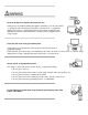
SAFETY SYMBOLS This manual uses the safety symbols below. They denote critical information. Please read them carefully. WARNING Failure to abide by the information in a WARNING may result in serious injury and can be life threatening. CAUTION Failure to abide by the information in a CAUTION may result in moderate injury and/or property or product damage. Indicates a prohibited action. Indicates to ground for safety. Copyright© 2005 EIZO NANAO CORPORATION All rights reserved.
As an ENERGY STAR® Partner, EIZO NANAO CORPORATION has determined that this product meets the ENERGY STAR guidelines for energy efficiency.
PRECAUTIONS IMPORTANT! ● ● This product has been adjusted specifically for use in the region to which it was originally shipped. If operated outside the region to which it was originally shipped, the product may not perform as stated in the specifications. To ensure personal safety and proper maintenance, please read this section and the caution statements on the unit (refer to the figure below).
Keep small objects or liquids away from the unit. Small objects accidentally falling through the ventilation slots into the cabinet or spillage into the cabinet may result in fire, electric shock, or equipment damage. If an object or liquid falls/spills into the cabinet, unplug the unit immediately. Have the unit checked by a qualified service engineer before using it again. Place the unit at the strong and stable place.
Use the enclosed power cord and connect to the standard power outlet of your country. Be sure to remain within the rated voltage of the power cord.Not doing so may result in fire or electric shock. To disconnect the power cord, grasp the plug firmly and pull. Tugging on the cord may damage and result in fire or electric shock. The equipment must be connected to a grounded main outlet. Not doing so may cause in fire or electric shock. Use the correct voltage.
Never touch the plug and power cord if it begins to thunder. Touching them may result in electric shock. When attaching an arm stand, please refer to the user's manual of the arm stand and install the unit securely with the enclosed screws. Not doing so may cause the unit to come unattached, which may result in injury or equipment damage. When the unit is dropped, please ask your dealer for advice. Do not continue using a damaged unit. Using a damaged unit may result in fire or electric shock.
Do not block the ventilation slots on the cabinet. ● ● ● Do not place any objects on the ventilation slots. Do not install the unit in a closed space. Do not use the unit laid down or upside down. Blocking the ventilation slots prevents proper airflow and may result in fire, electric shock, or equipment damage. Do not touch the plug with wet hands. Doing so may result in electrical shock. Use an easily accessible power outlet.
In order to suppress the luminosity change by long-term use and to maintain the stable luminosity, use of a monitor in lower brightness is recommended. The screen may have defective pixels. These pixels may appear as slightly light or dark area on the screen. This is due to the characteristics of the panel itself, and not the product. The backlight of the LCD panel has a fixed life span. When the screen becomes dark or begins to flicker, please contact your dealer.
1. Introduction Thank you very much for choosing an EIZO Color Monitor. 1-1.
1-3. Controls & Connectors Front (1) ScreenManager® Monitor Adjustment menu (2) FineContrast Menu Directly touching the left or right button allows you to select a FineContrast mode. (3) Input Signal Selection Switch (SIGNAL) Switch the input signals when connecting 2 PCs. (4) Auto Adjustment Switch (AUTO) Adjust the screen to appropriate condition automatically (analog input only). (5) Enter Switch (ENTER) Show the ScreenManager on the screen. Confirm the setting / adjustment function.
(9) Stand (Detachable) The LCD monitor can be used with an optional arm stand by removing the stand (See "6. ATTACHING AN ARM"). (10) Security Lock Slot Allows for connection of a security cable. This lock supports Kensington's MicroSaver security system. For further information, please consult: Kensington Technology Group 2855 Campus Drive, San Mateo, CA 94403 USA Tel.: 800-650-4242, x3348, Intl: 650-572-2700, x3348 Fax: 650-572-9675 http://www.kensington.com (11) Cable Holder House the cables.
2. CABLE CONNECTION 2-1. Before Connecting Before connecting your monitor to the PC, change the display screen settings (Resolution and frequency) in accordance with the charts below. ● When your computer and display support VESA DDC, the suitable resolution and the refresh rate are set by just plugging your display into the computer without any manual settings.
720×400 70Hz VGA TEXT 800×600 60Hz VESA 1024×768 60Hz VESA 1280×960 60Hz 1280×1024 60Hz VESA 1600×1200 60Hz VESA 1680×1050 60Hz VESA CVT, VESA CVT RB (Reduced Blanking) 1920×1200 60Hz VESA CVT RB (Reduced Blanking) 162 MHz (Max) VESA 2-2. Connecting the Signal Cable ● Be sure that the power switches of both the PC and the monitor are OFF. 1. Plug the signal cable into the connector at the rear of the monitor and the other end of the cable into the video connector on the PC.
Video Output Connector / D-Sub mini 15 pin Input Connector (monitor) / D-Sub mini 15 pin Signal Cable (FD-C16 enclosed) Video Output Connector / D-Sub 15 pin Input Connector (monitor) / D-Sub mini 15 pin Signal Cable (FD-C16 enclosed) + Macintosh Adapter (Optional) ● ● ● Standard graphics card Power Macintosh G3 (Blue & White) / Power Mac G4 (VGA) Macintosh Digital Input Signal Cable Connector of the PC Video Output Signal Cable (FD-C39 enclosed) Connector / DVI Input Connector (monitor) / DVI ●
4. Lead the power cord and signal cable into the cable holder at rear of the monitor. ● The cables are recommended to lead with slight sag for the smooth motion of the stand and the Portrait/ Landscape display. 5. Adjust the "height", "front and back position" and "angle" of the monitor. Grip both side of the center part of the monitor and move slowly (refer to the right figure.) (1) Adjust the height of the monitor. To heighten, push the monitor backward. To lower, pull the monitor forward.
(3) If necessary, fine adjust the height of the monitor. 6. Turn on the monitor's Power switch and then turn on the PC's power. The monitor's power indicator will light up (blue). If an image does not appear, refer to the "7. TROUBLESHOOTING" for advice. Whenever finished, turn off the PC and the monitor. ● ● ● When turning on the monitor, the kind of the input signal (Signal1 or 2/Analog or Digital) is displayed for a few seconds on the right top corner of the screen.
2-3. Connecting Two PCs to the Monitor Two PCs can be connected to the monitor through the DVI-I and the D-Sub mini 15 pin connector on the back of the monitor. Connecting Examples SIGNAL 1 SIGNAL 2 D-Sub Signal Cable (Ex.1) Analog mini 15 (FD-C16 enclosed) pin Signal Cable (FD-C39 enclosed) D-Sub Signal Cable (Ex.2) Analog mini 15 (FD-C16 enclosed) pin Signal Cable (FD-C16 optional) Signal Cable (FD-C39 enclosed) Signal Cable (FD-C39 optional) (Ex.
This function is used to select which PC will have priority to control the monitor when utilizing two PCs. The monitor constantly checks the input signals and switches automatically in accordance with the "Input Priority" setting (see table below). Once a priority is set, whenever a change of signal is detected at the selected input, the monitor will switch the input to that signal. In the case of only one signal being present at either input, the monitor automatically detects and displays that signal.
3. ScreenManager 3-1. How to use the ScreenManager ScreenManager allows you to adjust screen performance though the main menu and select a FineContrast mode easily. ● Main Menu and FineContrast Menu cannot be activated at the same time. 1. Entering the ScreenManager Touch the Enter switch once to display the main menu of the ScreenManager. 2. Making Adjustments and Settings 1. Select the desired sub menu icon using the Directing switch and touch the Enter switch. The sub menu appears. 2.
FineContrast Menu Directly touching the left or right switch allows you to select the best suited mode for screen display from 5 FineContrast modes; Custom, Movie, Picture, Text and sRGB. To exit the menu, touch the Enter switch. 3-2. ScreenManager Adjustments and Settings The following table shows all the ScreenManager's adjustment and setting menus. "*" indicates adjustments of analog input only and "**" indicates digital input only.
Menu Settings Menu Off Timer Set the menu displaying time. Translucent Set the transparency of the background. Power Indicator Make non-light for blue lighting when the screen is displayed. (Power Indicator Setting.) Reset Return to the factory Default settings. Information Information Review the ScreenManager's settings, model name, serial number and usage time. *2 English, German, French, Spanish, Italian, Swedish and Japanese Language Select the ScreenManager's language.
Custom To adjust the color settings according to your preference Movie Animated images Picture Photo or picture image Text Text on word processor or spreadsheet software sRGB To display the screen images based on those original colors (ex. over the Internet) Color Adjustment of the Mode Settings , and settings can be adjusted on the FineContrast menu. Select the desired function icon with the Up/Down Directing switches and adjust with the Left/Right Directing switches.
[Procedure] 1. Select in the ScreenManager menu. 2. Select "Enable" and touch the Right and Left switches to adjust the "On Period" (1 to 23 hours). [Off Timer System] PC On Period (1H - 23H) Last 15 min. in "On period" "On period" expired Monitor Operation Advance Notice* Power Indicator Blue 1 Blue Flashing Power Off Off *1 Advance notice will be given 15 minutes before the monitor automatically enters the "Power Off" mode.
4. ADJUSTMENT 4-1. Screen Adjustment ● Allow the LCD monitor to stabilize for at least 20 minutes before making image adjustments. The monitor displays the digital input image correctly based on its pre-setting data. Analog Input Screen adjustments for the LCD monitor should be used in suppressing screen flickering and also for adjusting the screen to its proper position. There is only one correct position for each display mode.
pattern to that as shown in the diagram on the following. 3. Adjust by using menu in the ScreenManager. (1) Vertical bars appear on the screen → Use the adjustment. Select the and eliminate the vertical bars by using the Right and Left of the Directing switches. Do not continuously touch the Directing switches, as the adjustment value will change quickly and make it difficult to locate the most suitable adjustment point.
pixels are fixed. The adjustment moves the image to the correct position. Select and adjust the position by using the Up, Down, Right and Left switches. If vertical bars of distortion appear after finishing the adjustment, return to adjustment and repeat the previously explained adjustment procedure.("Clock" → "Phase" → "Position") (4) Screen image is smaller or larger than the actual screen images. → Use the adjustment.
4-2. Displaying Lower Resolutions The lower resolutions are enlarged to full screen automatically. Using the function in the menu enables to change the screen size. 1. Enlarge the screen size when displaying a low resolution. → Select the . Select the in the others menu and select the screen size by using the up and down switches. Menu Function Displays the picture on the screen in full, irrespective of the picture's resolution.
→ Set the . In the mode or mode, the outer area (border) is usually black. Select in the menu and adjust by using the right and left switches. 4-3. Color Adjustment Color settings of each FineContrast mode can be adjusted and saved by using the menu of the ScreenManager. In the analog input, perform the "Range Adjustment" before making the color adjustments. During color adjustments, the FineContrast mode cannot be changed.
● ● ● Allow the LCD monitor to stabilize for at least 20 minutes before making image adjustments. (Allow the monitor to warm up for at least 20 minutes before making adjustments.) Performing the of the menu returns the color settings of the selected mode to the default settings. The values shown in percentages represent the current level within the specific adjustment. They are available only as a reference tool.
● Using adjustment may not obtain proper tone reproduction. 0 ~ 100% By adjusting the red, green and blue color tones for each mode, custom colors can be defined. Display a white or gray background image and adjust the . To change each color (red, green and blue) Gain ● ● The values shown in the percentage are available only as a reference tool. Setting the invalidates the adjustment. setting returns to the defaul.
Operation Operation STAND-BY Power saving SUSPEND Power saving OFF Blue Yellow [Power Resumption Procedure] Operate the mouse or keyboard to return to a normal screen. Digital Input This monitor complies with the "DVI DMPM" [Procedure] 1. Set the PC's power saving settings. 2. Select "DVI DMPM" from the menu.
5. MAKING USE OF USB (Universal Serial Bus) This monitor provides a hub which supports the USB standard. When connecting to a USB compliant PC or another hub, the monitor functions as a hub to which the USB compliant peripherals can be easily connected. Required system environment ● ● ● ● ● ● ● ● PC equipped with USB ports or another USB hub connected to the USB compliant PC Windows 98/2000/Me/XP // Mac OS 8.5.
Connecting Examples ScreenManager Pro for LCD (for Windows) For further details about the "ScreenManager Pro for LCD (for Windows)", refer to the EIZO LCD Utility Disk.
6. ATTACHING AN ARM The LCD monitor can be used with an arm by removing the tilt stand and attaching the arm stand to the LCD monitor. ● ● ● If you will use the arm or stand of other manufacturers, confirm the followings to the manufacturers before selecting.
7. TROUBLESHOOTING If a problem persists even after applying the suggested remedies, contact an EIZO dealer. ● No picture problems → See No.1 ~ No.2 ● Imaging problems → See No.3 ~ No.14 ● Other problems → See No.15 ~ No.19 ● USB problems → See No.20 ~ No.21 Problems Points to check with Possible Solutions ● Check that the power cord is correctly connected. If the problem persists, turn off the monitor power for a few minutes, then turn it back on and try again. Try touching the Power switch.
3. Display position is incorrect. ● ● 4. Screen image is smaller or larger than the actual screen images. ● Adjust the image position using the . If the problem persists, use the graphics board's utility software to change the display position if available. Adjust the resolution using the . 5. Vertical bars of distortion appear. ● 6. The characters and images have several vertical bars on their right side. ● Decrease the vertical bars using the .
12. The screen has defective pixels (e.g. slightly light or dark). ● ● 13. Fingerprints remain on the screen. ● 14. The noise appears on the screen. ● This is due to the characteristics of the panel itself, and not the LCD product. Leaving the screen white may solve the problem. Change the mode in in the menu. is disabled in the following cases. ● 15. The cannot be selected. ● ● ● 16. The Main menu of ScreenManager does not operate. ● ● ● 17.
● ● 20. PC is hung up. / The peripherals connected to the downstream ports do not operate. ● Check that the USB cable is correctly connected. Check the downstream ports by connecting the peripherals to other downstream ports. If the problem is solved by doing this, contact an EIZO dealer. (For details, refer to the manual of the PC.) Try executing the following method. ● ● Restarting the PC Connecting the PC and peripherals directly If the problem is solved by doing this, contact an EIZO dealer.
8. CLEANING Periodic cleaning is recommended to keep the monitor looking new and to prolong its operation lifetime. ● Never use thinner, benzene, alcohol (ethanol, methanol, or isopropyl alcohol), abrasive cleaners, or other strong solvents, as these may cause damage to the cabinet or LCD panel. Cabinet To remove stains, wipe the cabinet with a soft, lightly moistened cloth using a mild detergent. Do not spray wax or cleaner directly into the cabinet. (For details, refer to the manual of the PC.
9. SPECIFICATIONS LCD Panel 61 cm (24.1 inch), TFT color LCD panel with Anti-Glare, Viewing Angle: Horizontal: 178°, Vertical: 178° CR ≥ 10 Dot Pitch 0.270 mm Horizontal Scan Frequency Analog 24 ~ 94 kHz (Automatic) Digital 31 ~ 76 kHz Analog 49 ~ 86 Hz (Automatic) (1600 x 1200: 49 ~ 76 Hz / 1920 x 1200: 49 ~ 61 Hz) Digital 59 ~ 61 Hz (VGA TEXT: 69 ~ 71 Hz) Vertical Scan Frequency Resolution Dot Clock (Max.) 1920 dots x 1200 lines Analog 202.5 MHz Digital 162 MHz Display Colors 16.
Operating: 0°C ~ 35°C (32°F ~ 95°F) Storage: -20°C ~ 60°C (-4°F ~ 140°F) Humidity 30% to 80% R.H. Non-condensing Temperature standard Rev. 2.0 complied self-powered hub USB port Upstream port x 1 Downstream port x 2 USB Communication Speed 480 Mbps (high), 12 Mbps (full), 1.5 Mbps (low) Power Supply Downstream: 500 mA for each (max.
4 short beeps Monitor not connected correctly. PC turned off. Monitor received unsupported signal frequency. 2 short beeps every 15 sec. Monitor is in the advance notice mode of the Off Timer. The power will be off within fifteen minutes.
Pin No. Signal 1 TMDS Data2- 2 TMDS Data2+ 3 Signal Pin No.
10. GLOSSARY Clock With the analog input signal display, the analog signal is converted to a digital signal by the LCD circuitry. To convert the signal correctly, the LCD monitor needs to produce the same number clock pulse as the dot clock of the graphics system. When the clock pulse is not correctly set, some vertical bars of distortion are displayed on the screen. DVI (Digital Visual Interface) A digital flat panel interface.
The LCD panel consists of a fixed number of pixel elements which are illuminated to form the screen image. This model display panel consists of 1920 horizontal pixels and 1200 vertical pixels. At a resolution of 1920 x 1200, all pixels are displayed as a full screen. sRGB (Standard RGB) "International Standard for Red, Green, and Blue color space" A color space was defined with the aim of the color matching between applications and hardware devices, such as monitors, scanners, printers and digital cameras.
APPENDIX/ANHANG/ANNEXE Preset Timing Chart for Analog input Timing-Übersichten für Analog Eingang Synchronisation des Signaux pour Analog numerique Based on the signal diagram shown below 30 factory presets have been registered in the monitor's microprocessor. Der integrierte Mikroprozessor des Monitors unterstützt 30 werkseitige Standardeinstellungen (siehe hierzu die nachfolgenden Diagramme).
VESA 800 × 600 @ 60 Hz 40.0 Posi. Posi. 37.88 60.32 VESA 800 × 600 @ 72 Hz 50.0 Posi. Posi. 48.08 72.19 VESA 800 × 600 @ 75 Hz 49.5 Posi. Posi. 46.88 75.00 VESA 800 × 600 @ 85 Hz 56.3 Posi. Posi. 53.67 85.06 VESA 1024 × 768 @ 60 Hz 65.0 Nega. Nega. 48.36 60.00 VESA 1024 × 768 @ 70 Hz 75.0 Nega. Nega. 56.48 70.07 VESA 1024 × 768 @ 75 Hz 78.8 Posi. Posi. 60.02 75.03 VESA 1024 × 768 @ 85 Hz 94.5 Posi. Posi. 68.68 VESA 1152 × 864 @ 75 Hz 108.0 Posi. Posi. 67.50 75.
[Applicable to white cabinet version only.] Congratulations! The display you have just purchased carries the TCO'03 Displays label. This means that your display is designed, manufactured and tested according to some of the strictest quality and environmental requirements in the world. This makes for a high performance product, designed with the user in focus that also minimizes the Impact on our natural environment.
[Applicable to black cabinet version only.] Congratulations! You have just purchased a TCO'99 approved and labelled product! Your choice has provided you with a product developed for professional use. Your purchase has also contributed to reducing the burden on the environment and also to the further development of environmentally adapted electronics products.
Fax: +46 8 782 92 07 Email (Internet): development@tco.se Current information regarding TCO'99 approved and labelled products may also be obtained via the Internet, using the address: http://www.tcodevelopment.com/ Environmental Requirements Flame retardants Flame retardants are present in printed circuit boards, cables, wires, casings and housings. Their purpose is to prevent, or at least to delay the spread of fire. Up to 30% of the plastic in a computer casing can consist of flame retardant substances.
The relevant TCO'99 requirement states that neither CFCs nor HCFCs may be used during the manufacture and assembly of the product. CFCs (freons) are sometimes used for washing printed circuit boards. CFCs break down ozone and thereby damage the ozone layer in the stratosphere, causing increased reception on earth of ultraviolet light with e.g. increased risks of skin cancer (malignant melanoma) as a consequence. Lead** Lead can be found in picture tubes, display screens, solders and capacitors.
Hinweis zur Ergonomie : Dieser Monitor erfüllt die Anforderungen an die Ergonomie nach ISO13406-2 mit dem Videosignal, 1920 Punkte ≥ 1200 Zeilen, RGB analog, 0,7 Vp-p und mindestens 60,0 Hz Bildwiederholfrequenz, non interlaced. Weiterhin wird aus ergonomischen Gründen empfohlen, die Grundfarbe Blau nicht auf dunklem Untergrund zu verwenden (schlechte Erkennbarkeit, Augenbelastung bei zu geringem Zeichenkontrast.
Recycle Auskunft Die Rücknahme dieses Produktes nach Nutzungsende übernimmt EIZO in Deutschland zusammen mit dem Partner eds-r gmbh rucknahmesysteme. Dort werden die Geräte in ihre Bestandteile zerlegt, die dann der Wiederverwertung zugeführt werden. Um einen Abholtermin zu vereinbaren und die aktuellen Kosten zu erfahren, benutzen Sie bitte folgende Rufnummer: 02153-73 35 00. Weitere Informationen finden Sie auch unter der Internet-Adresse: www.eizo.de.