
Specifications


Ǧ TAPERED CRAFTSMAN COLUMNS
TAPERED COLUMN SPECIFICATIONS
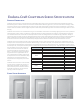
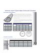
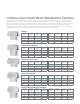
Tapered columns are available plain, or with three paneled options: standard raised
panel, “square corner” raised panel, and recessed panel. (Since all tooling used for
routing the panels is done with round bits, there will always be some radius in the cor-
ners. The “square corner” style uses the smallest bit possible to minimize that radius -
about
1/8”.)
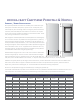
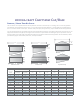
Standard heights available for tapered columns are 4’, 5’, 6’, 8’ and 10’. Custom sizes
may be requested, up to 24’ in height, and up to 48” in width.
Shaft heights for standard columns will be
1/2” less than the nominal height (see
diagram, dimension “A”.) For example, a 5’ high column will ship with a shaft that is
4’-11
1/2” tall. If the installation does not use the 1” base platform or 1” cap platform,
the column can still achieve the full 5’ stated height, since the cap molding can cover
the
1/2” gap at the top. (At least 1/4” gap is required at the top on all installations to
compensate for product thermal expansion.)
Net widths of shafts will be
3/8” less than nominal. Custom tapers may be requested by
specifying the bottom width and top width of the shaft. Cap and base trim and plat-
forms will be adjusted as needed for the revised shaft width.
See the cap and base specifications page for available cap/base styles.
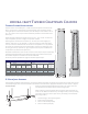
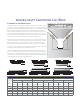
E-Z LOCK JOINT ASSEMBLY
Vertical edges of Craftsman shafts (tapered, non-tapered, pedestal and newel post styles) all incorporate the E-Z Lock miter joint for
consistently straight miters. See the installation instructions for full information. Appropriate adhesives are PVC cement or polyure-
thane glue. Double hot-dipped galvanized screws or pin-nails or other non-
corrosive fasteners should be used to reinforce the glue joint.
Please note the correct assembly of the E-Z Lock joint shown at the left. The
screws or nails MUST be installed only in the edges shown (3 and 4). Installing
on the other edges may result in open seams. (Pre-drilling is recommended
when using screws.)
1. Glue both edges, slide 1st joint together.
2. Slide second joint together.
3. Nail or screw second joint (#3).
4. Nail or screw first joint (#4).
G
HI
B
E
A
D
C
F
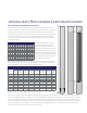
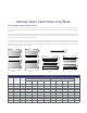
Shaft Specifications
Nominal
Width
Shaft Dimensions Panel Dimensions†
Bottom Top
From
Bottom of
Shaft (F)‡
From Top
of Shaft (G)
From Side
of Shaft (I)
Width of
Routed
Channel (H)
Outside
Width (B)
Inside
Width (C)
Outside
Width (E)
Inside
Width (D)
10” 9 5/8” 8 3/8” 5 5/8” 4 3/8” 10 1/2” 2 1/2” 1 1/4” 3/4”
12” 11 5/8” 10 3/8” 7 5/8” 6 3/8” 10 1/2” 2 1/2” 1 1/2” 1 1/4”
16” 15 5/8” 14 3/8” 11 5/8” 10 3/8” 10 1/2” 2 1/2” 1 1/2” 1 1/4”
20” 19 5/8” 18 3/8” 13 5/8” 12 3/8” 10 1/2” 2 1/2” 1 1/2” 1 1/4”
24” 23 5/8” 22 3/8” 15 5/8” 14 3/8” 10 1/2” 2 1/2” 1 1/2” 1 1/4”
† Dimensions except width also apply to recessed panel shafts.
‡ Dimension shown is for standard shafts. On custom height columns the panels start 5
1/4” from the bottom.
1.
2.
3.
4.
E-Z Lock Assembly