
Specifications


Ǧ CRAFTSMAN PEDESTALS & NEWELS
PEDESTAL / NEWEL SPECIFICATIONS
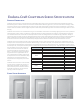
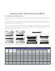
Non-tapered pedestals and newels are available plain or with these pan-
eled options: standard raised panel, “square corner” raised panel, and
recessed panel. (Since all tooling used for routing the panels is done with
round bits, there will always be some radius in the corners. The “square
corner” style uses the smallest bit possible to minimize that radius - about
1/8”.) Fluting is available as a custom option.
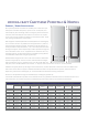
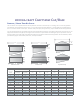
Shaft heights for standard pedestals and newels (dimension A of diagram)
are 1” less than nominal. The pedestals are all topped with a 1” platform,
thus achieving the stated net height. This platform, like the platforms on
the cap and base for tapered columns, is “V” cut to easily install around an
existing load support. See the tapered cap and base specifications page for
more information on the “V” cut. Top platforms for newels are not V-cut,
providing a flat top. An optional pyramid cap is available (no top platform
is included with newels when using the pyramid cap.)
Standard widths range from 8” to 30” in two-inch increments. Net widths
of shafts are typically
3/8” less than nominal. Custom widths and heights
may be requested in any size, typically from 2’ to 4’ tall and 48” wide. Cus-
tom plans, such as double-width for two columns, “L” shape for three columns on a corner, etc., are also possible.
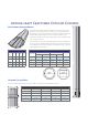
Pedestals are typically about 1/3 the height of the overall column, and the shaft width is about the same as the width of the
base on the column which it supports. Pedestals and newels are often incorporated with rail systems, and ǁĞĂƌĞ able to
adjust sizes, panel locations and heights, etc. to accommodate the attachment of railing components.
See the Trim Kit specifications page for available styles, including the pyramid cap.
It should be noted that like all products in the Craftsman Series line, pedestals and newels need to be installed around a struc-
tural component. The installer may need to provide blocking at the bottom and top to prevent lateral movement.
A
B
C
D
E
FG
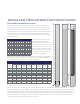
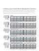
Shaft Specifications
Nominal Width
Shaft Widths Panels (Standard Trim) Panels (Prairie Trim) Panels
Outside (B) Inside (C)
From Bottom of
Shaft (D)
From Top of
Shaft (E)
From Bottom of
Shaft (D)
From Top of
Shaft (E)
Width of Router
Channel (F)
From Side of
Shaft (G)
6” 5 5/8” 4 3/8” 4 3/4” 3 3/4” 4 3/4” 2 5/8” 3/4” 1 1/4”
8” 7 5/8” 6 3/8” 4 3/4” 3 3/4” 4 3/4” 2 5/8” 1 1/4” 1 1/2”
10” 9 5/8” 8 3/8” 4 3/4” 3 3/4” 4 3/4” 2 5/8” 1 1/4” 1 1/2”
12” 11 5/8” 10 3/8” 4 3/4” 3 3/4” 4 3/4” 2 5/8” 1 1/4” 1 1/2”
14” 13 5/8” 12 3/8” 5 1/4” 4 1/4” 5 1/4” 3 1/8” 1 1/4” 2”
16” 15 5/8” 14 3/8” 5 1/2” 4 1/2” 5 1/2” 3 3/8” 1 1/4” 2 1/4”
18” 17 5/8” 16 3/8” 5 3/4” 4 3/4” 5 3/4” 3 5/8” 1 1/4” 2 1/2”
20” 19 5/8” 18 3/8” 6” 5” 6” 3 7/8” 1 1/4” 2 3/4”
22” 21 5/8” 20 3/8” 6 1/4” 5 1/4” 6 1/4” 4 1/8” 1 1/4” 3”
24” 23 5/8” 22 3/8” 6 1/2” 5 1/2” 6 1/2” 4 3/8” 1 1/4” 3 1/4”
26” 25 5/8” 24 3/8” 6 3/4” 5 3/4” 6 3/4” 4 5/8” 1 1/4” 3 1/2”
28” 27 5/8” 26 3/8” 7” 6” 7” 4 7/8” 1 1/4” 3 3/4”
30” 29 5/8” 28 3/8” 7 1/4” 6 1/4” 7 1/4” 5 1/8” 1 1/4” 4”