ELAN DIGITAL SYSTEMS LTD. LITTLE PARK FARM ROAD, SEGENSWORTH WEST, FAREHAM, HANTS. PO15 5SJ. TEL: (44) (0)1489 579799 FAX: (44) (0)1489 577516 e-mail: sales@elandigitalsystems.com website: http://www.elandigitalsystems.com USBscope50 USERS GUIDE ES370 Important Notice: Please refer to Safety Data 4.4.1, before using this instrument All Trademarks are duly acknowledged. The USBscope50 is Patent Pending. REVISION HISTORY ISSUE PAGES DATE NOTES 1 2 3 30 30 31 04.07.2005 08.07.2005 15.07.
CONTENTS 1 OVERVIEW....................................................................................................5 2 ABOUT THE USBSCOPE50.........................................................................6 2.1 General................................................................................................................6 2.2 USBscope50 Architecture..................................................................................7 2.3 Using More Than One USBscope50........................
.2 Linux Ubuntu...................................................................................................29 3.3 Troubleshooting...............................................................................................30 4 HARDWARE SPECIFICATION...................................................................31 4.1 Power Requirements........................................................................................31 4.2 Mechanical........................................................
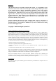
Disclaimer This document has been carefully prepared and checked. No responsibility can be assumed for inaccuracies. Elan reserves the right to make changes without prior notice to any products herein to improve functionality, reliability or other design aspects. Elan does not assume any liability for loses arising out of the use of any product described herein; neither does its use convey any license under its patent rights or the rights of others.
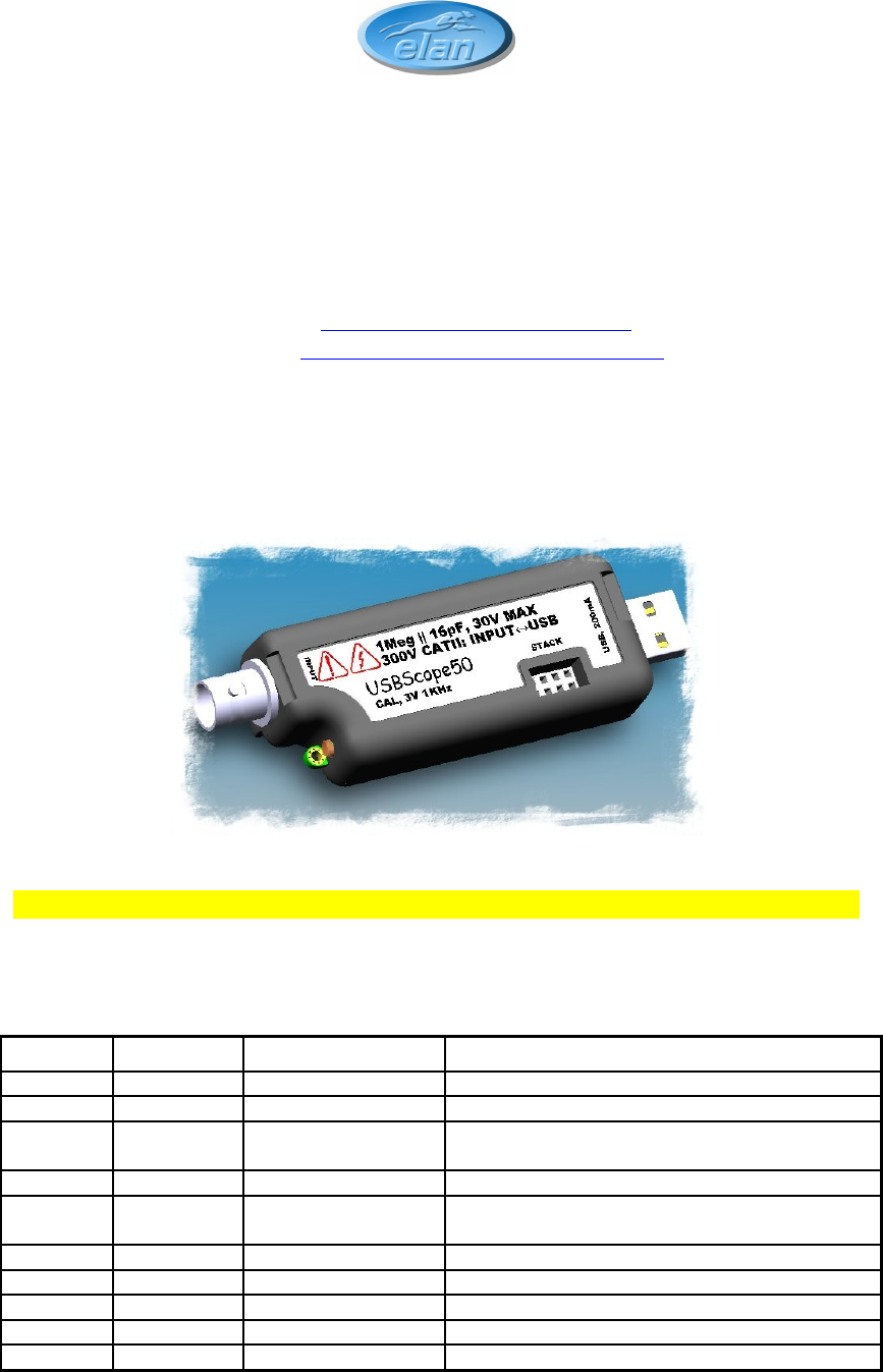
1 OVERVIEW The USBscope50 is an isolated digital storage oscilloscope that has the following features: • Single channel scope with BNC input and USB PC interface • Each USBscope50 can be stacked to increase channel count (each requires its own USB connection)1 • 300V Cat II isolation between BNC ground and USB ground2 This means that there is no DC path through the USBscope50 from your scope ground clip to the PC’s ground • 50MSample/sec single shot sample rate • 1GSample/sec equivalent sample rate3 • Time
2 ABOUT THE USBscope50 2.1 General The USBscope50 uses a 50MSample/sec 8-bit A-to-D converter. The A-to-D and front-end circuits that process the input waveform, and the digital stages that acquire and store the waveform are all powered from the USB host interface via an isolated supply. This means that there is no galvanic connection between the BNC ground (or BNC centre terminal), and the USB interface.
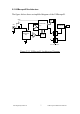
2.2 USBscope50 Architecture The figure below shows a simplified diagram of the USBscope50. STACK CONN AC/DC CONTROLLER BNC COMP USB CONTROLLER Trigger DATA ATTENUATOR 1Meg AMP 8-BIT ADC PSU ISOLATION BARRIER Figure 2.2-1 USBscope50 Architecture Diagram Elan Digital Systems Ltd.
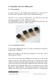
2.3 Using More Than One USBscope50 2.3.1 Stacked Mode A unique feature of the USBscope50 architecture is that up to 4 devices6 can be stacked to make a multi-channel instrument. In order to use a stacked configuration, you will need to use the connectors supplied with the USBscope50 unit. You should have a pair of connectors supplied with each unit, one long one and one short one, similar to these: 2.3.1.
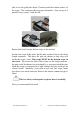
able to see the gold pins about 2-3mm beyond the bottom surface of the scope. The connectors have no pin orientation…they can go in 2 possible ways round…both are OK. Repeat this for all except the last scope to be stacked. For the last scope in the stack, do the same as above but use the short length connector. This time, the pins are shorter so they stop well inside the scope’s case. This scope MUST be the bottom scope in the stack.
Start with the bottom scope. Hold it in one hand, and put the next scope on top of the 1st, the same way around. Align the stacking connectors and when the stacking connectors are partly mated engage the front “P” shaped clip (BNC end) on the 2nd scope into the “P” shaped slot on the 1st scope. Now, bring the back edge “P” clip (USB end) of the 2 nd scope down until it clicks into the 1st scope’s slot. These two scopes are now mated.
end). With moderate force, the top scope will pop up and come free. Remove the stacking connector from the free scope. Repeat this for all scopes in the stack. 2.3.1.3 USB Connections For Stacked Configurations All stacked scopes need a USB connection. A standard hub may be useful for multi-channel stacks to get enough USB ports. Each scope needs about 200mA. Plugging more than 2 scopes into a hub will mean that the hub may need to be powered externally.
The LED on the scope will blink rapidly and message dialog with the device information will appear on the screen. Pressing ESC key will close this window. Repeat this for each channel in the stack to identify them. If you like, you can stop the software, and unplug all the scopes from their USB connections, and then re-stack them in their channel order. 2.3.1.
• Do make sure that each stack connector is properly seated in place before trying to stack another channel on top • Don’t allow water or dirt etc to enter the scope via the stack connector access hole • Do remember that scopes in the stack are NOT isolated from each other, they are only isolated from the USB ports. To re-iterate, stacked scopes have their BNC connector bodies connected together through the stack connector. 2.3.
2.3.2.2 Software For Non-Stacked Configurations By default when you run USBscope50, it will automatically detect all the scopes connected via USB and will also check to see if the scopes are electrically connected together via the stack. To run in Non-Stacked MIS mode, power USBscope50s via USB port and run the software. Make sure that software is not running in demo mode and that number of detected devices corresponds to number of powered devices.
appearance in Settings → Channel Colours and in Settings → Chart Settings. 2.4 Input Ranges The USBscope50 supports 3 settings on its input attenuator. These are then adjusted in the software to expand the range which user can adjust by pressing the arrow keys. The ranges at the BNC input depend on the type of scope probe used: A “x1” probe causes no signal attenuation and will result in nominal full-scale input ranges.
In DC coupling mode, the capacitor is bypassed and the bandwidth is DC up to 75MHz. 2.4.1 Offset Nulling The input stages of the USBscope50 will naturally tend to cause a small DC offset error in any readings, and this will change from range to range and from scope to scope. In order to null this offset out, the software is able to subtract a DC level from all its readings and its plots, that will help to remove this error.
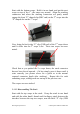
The USBscope50 includes a probe compensation output9. This must be turned on using the USBscope50 Software. In the channel tab you will find a button with COMP label. Click on COMP to turn ON / OFF probe compensation signal. When COMP button is coloured, you should see a probe compensation output. Once enabled, the compensation output is a 0 to 3V (approx) square wave with 50% duty cycle and 1KHz frequency. The USBscope50 can work with scope probes that list an adjustment range that includes 16pF.
4. Set the timebase to 100us/div 5. Now connect your probe tip to the compensation output on the scope. You should see a square wave something like this or it may look more like this 6. You may find you need to connect the ground clip to either the BNC ground or use the GND pad near the compensation output11 to achieve a clean waveform with minimal mains “hum” 11 Be careful not to short-circuit the GND pad to the COMP output with the ground clip.
7. Now, slowly adjust the trimmer in the probe body until you achieve the best square wave shape that you can. By this we mean nice square corners and minimum over and under shoot near the edges. A small amount of over shoot is preferable to an adjustment with “curved” square wave corners: this would mean that the scope will attenuate high frequency signal components whereas a small amount of overshoot will mean that the scope will tend to slightly amplify high frequency signal components.
2.6 Acquisition Modes The USBscope50 can acquire waveforms in two different ways. Single shot and continuous run mode. 2.6.1 Single Shot In this mode, the ADC is clocked at up to 50MegaSamples/sec. Each sample is placed into the buffer and then the buffer is painted on the screen. This mode is the one to use for non-repetitive signals i.e. single pulses, irregular bus events etc. It can also be used for repetitive waveforms.
normal. To avoid this effect, always pick the fastest single shot timebase consistent with being able to view the waveform in question. 2.6.2 Random Interleaved Sampling This mode is a little more complex and is suited only to observing certain types of waveform. The USBscope50 includes special circuitry that allows it to trigger off the input waveform and also to be able to measure the time between the trigger instant and the first ADC sample that is taken.
the screen as a result…the software forces the sweep data into one or other of the bins even though the data may have been at one end of the “bin” or the other. RIS mode is not well suited to very slow input signals or signals that have jitter. This will lead to an uncertainty in the trigger instant and hence the sweep data will appear in the wrong “bins” and so the displayed waveform will not “lock” on the screen over time.
2.7.1 USBscope50 continuous run in Free Mode In this mode the acquisition begins just after the software has set up the scope. The scope will effectively free run, with no attempt to lock to the input waveform and displaying all the the graph as soon as data is available. Free mode is good for checking DC levels etc. 2.7.2 Normal Triggering This includes Rising Edge, Falling Edge, More Than and Less Than trigger options.
2.9 Trigger Threshold You can adjust the trigger voltage that is used for Norm Modes, either by moving the slider from the trigger tab. Select View → Trigger Options and trigger tab should appear on the right hand side of the USBscope50 Software application. 2.10 Data manipulation 2.10.1 Save Graph With USBscope50 Java software you can save graph in one of the following formats: jpg, pnp or pdf. Please select menu option File → Save Graph. 2.10.
Remember to stop the acquisitions before saving the data otherwise the most recent data will be saved. Data is saved in ASCII text format and will import directly to Open Office Spreadsheet, Excel, MathCAD. 2.10.2.1 Example Data File There are 3000 sets of numbers. Document contains the header that defines the acquisition mode used. //USBscope50 Software loaded this file with the 3000 graph points. //Use software option Edit -> Import to recreate the graph.
2.11 Import Graph Data Any text file with the header of exported file and 3000 points can be imported on the graph. Select Edit → Import Graph Data and these data points will appear on the channel set in the file header DATA On CHANNEL. When you select a text file to import, software will scan through it and will warn you if any of the header settings are missing, and also will point out the line number where error encountered. All lines beginning with “//” in the text file will be ignored by software.
2.12 Software Development Kit (SDK) for USBscope50 While running the USBscope50 Java application try selecting Help option from the software menu or pressing F1 key. You should get some additional help pages on how to use the software and also detailed information on SDK for USBscope50. Sources of the Software, as well as driver sources are made available for you to download from our website. This information should aid you if you wish to write your own GUI or device driver. Elan Digital Systems Ltd.
3 SOFTWARE INSTALLATION 3.1 Windows XP and Vista14 Before plugging in the hardware: Use the supplied install CD and run the setup program. This will copy all the required files and drivers to your PC. After running the setup program: Insert the USBscope50 into a free USB socket, or into a USB hub port. A USB extension cable can be used if needed. During installation hardware device is detected: “USBscope50”. After installation the device manager will look like this16: 14 15 .
Once the hardware has installed, there is no need to make any settings for the allocated COM port…the software takes care of all this at run time17. Start the USBscope50 software and you will see the following display: To find out what the various buttons and knobs do, simply hover over them for a brief explanation. 3.2 Linux Ubuntu Elan USB Test & Measurement equipment consists of 4 different USB devices USBscope50, USBwave12, USBcount50 and USBpulse100. These devices all use SiLabs driver, cp2101.
Please copy USBscope50Drvr.so to /usr/lib making sure you have root privileges. Copy USBscope50_Software.jar and lib folder in the same location. To run this Java Application you need Java Runtime Environment (JRE). USBscope50 Software is not bound to a JRE version, but we would advise customers to keep JRE up to date. Software was tested on JRE version 6. For more information and instruction on how to install JRE, please refer to Java Sun website www.java.com.
4 HARDWARE SPECIFICATION All parameters typical @ 20°C unless otherwise stated 4.1 Power Requirements Supply Voltage: Total Supply Current: 5.0V ±10% from host USB bus 200mA avg 4.2 Mechanical Mass: Case Material Data: Size (typical in mm): 42g typ. Polycarbonate (UL94V rated) 99.618 x 30.6 x 17.519 4.
4.4 Performance 4.4.1 Safety Data and Maximum Ratings Important Safety Precautions Always observe these when using the USBscope50 The USBscope50 contains no user serviceable parts inside. Do not open the plastic housing. There may be lethal voltages inside the plastic housing. Do not use the instrument if the housing is damaged or is poorly fitting. In such a case do not connect anything to the USBscope50 to avoid a hazard. The USBscope50 will have to be repaired or replaced in such a situation.
Isolation rating: 300V CAT II, 500V CAT I between BNC ground and USB ground Transient isolation21: BNC ground to USB ground +/-2.5KV 22 Isolation capacitance : 1000pF typ between BNC ground and USB ground Maximum Measured Voltage: Between BNC center and BNC ground: +/-30V. Absolute Maximum Input Voltage23: Between BNC center and BNC ground: 148Vrms or 148Vdc. 4.4.
4.4.3 Dynamic Performance Maximum ADC single shot rate: Maximum effective sample rate25: Sample rates available: Sample rate accuracy: Stacked scope channel skew: Analogue 3dB bandwidth: AC coupling 3dB high pass freq: Analogue trigger 3dB bandwidth26: SFDR: 50MSPS 1GSPS 4ns/div to 4s/div in 1,2,4 sequence 0.02% typ ±2ns between any channel pair typ 75MHz typ 3.4Hz typ 60MHz typ 50dB typ Compensation output:0 to 3V nominal 1KHz square wave, absolute max source/sink current 1 mA 4.4.