
User guide
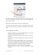
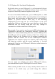
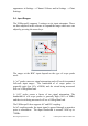

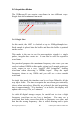
Table Of Contents
- 1 OVERVIEW
- 2 ABOUT THE USBscope50
- 2.1 General
- 2.2 USBscope50 Architecture
- 2.3 Using More Than One USBscope50
- 2.4 Input Ranges
- 2.5 Probe Compensation
- 2.6 Acquisition Modes
- 2.7 Trigger Modes
- 2.8 Trigger Position
- 2.9 Trigger Threshold
- 2.10 Data manipulation
- 2.11 Import Graph Data
- 2.12 Software Development Kit (SDK) for USBscope50
- 3 SOFTWARE INSTALLATION
- 4 HARDWARE SPECIFICATION

The USBscope50 includes a probe compensation output
9
.
This must be turned on using the USBscope50 Software. In the
channel tab you will find a button with COMP label. Click on
COMP to turn ON / OFF probe compensation signal. When COMP
button is coloured, you should see a probe compensation output.
Once enabled, the compensation output is a 0 to 3V (approx) square
wave with 50% duty cycle and 1KHz frequency.
The USBscope50 can work with scope probes that list an adjustment
range that includes 16pF. It is best to use probes that have a range
that puts the 16pF point near the middle of the range, for example
the HP10071A type probe lists an adjustment range of 9-17pF and
our tests show that whilst it is easy to compensate this probe against
the USBscope50, the trimmer in the probe body is certainly quite
close to the top end of its range. There are many probe choices on
the market, and lots of them list ranges that span 16pF.
10
To compensate your probe follow these steps:
1. Connect your x10 probe to the USBscope50 software and run
the USBscope50 software
2. Set the input range to 500mV/div, x10 probe, coupling to AC
3. Use the channel tab and click on the “COMP” button to turn
on the compensation output
9
Later models have a dual pad compensation point that includes a GND pad
10
Some very high frequency low capacitance probes may not be suitable for use with the USBscope50
Elan Digital Systems Ltd. 17 USBscope50 USER’S GUIDE Iss8