
Integration Manual
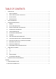


Table Of Contents
- 1 Introduction
- 2 Safety Information
- 3 Integration instructions
- 3.1 General
- 3.2 List of applicable rules
- 3.3 specific operational use conditions
- 3.4 Limited module procedures
- 3.5 Trace antenna design
- 3.6 RF exposure considerations
- 3.7 AntEnnas
- 3.8 Label and compliance information
- 3.9 test modes and additional testing requirements
- 3.10 Additional testing, Part 15 Subpart B disclaimer
- 3.11 Mechanical installation
- 3.12 Electrical connection
- 3.13 Programmation/Software integration
- 4 Compliance Statements
- 5 Integrator and host requirements
- APPENDIX

© 2022 ELATEC GmbH – TWN4 MultiTech 2 LEGIC M LF HF integration manual DocRev1 – 06/2022 Page 5 of 12
3.12 ELECTRICAL CONNECTION
The module can be connected to the host with a DF11 connector*.
PIN
PIN NAME
FUNCTION
1
UGND
USB Ground. Fed to main Ground through noise-reduction circuit.
2
USB_D+
USB Data +
3
UVCC
USB VCC (5V). When using RS-232, connect this to external 5V supply.
4
USB_D-
USB Data -
5
V24_RXD
RS-232 RXD (Input)
6
GND
Ground
7
V24_TXD
RS-232 TXD (Output)
8
Hostsense
Active-low, enables RS-232 transceiver. Short to Pin 6 (GND) when using RS-232.
*Hirose DF11 series, 2mm pitch or type equivalent. In case the reader module is not connected with a cable delivered by ELATEC,
the reader module can only be connected with a cable equipped with the following connector:
Manufacturer: Shenzhen Le Qing Lin Hai Electronics Co., Ltd
Part no.: A2002-H04X2
3.13 PROGRAMMATION/SOFTWARE INTEGRATION
n/a