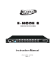
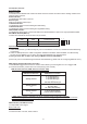
Sub-Net Universe X-NET 8 ArtNET 250k Power ArtNET Ethernet 1=Ground 2=Data3=Data+ 8 Universal DMX System On 1000k Baud rate DMX Trigger DMX 1 DMX 2 DMX 3 DMX 4 DMX 5 DMX 6 DMX 7 DMX 8 Instruction Manual P/N: 24-004-1497-00 Rev1.
Table of Contents Part I: About E-NODE 8 Part II: X-Soft-Net(Holding System) Operation (1) How to Setup (2) How to Map (3) How to playback preset Scenes by running X-Software & DMX Trigger Operation Incl.
Part I About E-NODE 8
About 8 Universal DMX System(E-NODE 8) Introduction: Thank you for your purchasing the Elation 8 Universe DMX System(E-NODE 8). To optimize the performance of this product, please read these operating instructions carefully to familiarize yourself with the basic operation of this system. The Elation E-NODE 8 is simple to use, 8 Universe DMX System . All system components have been tested at the factory before being shipped to you.
Controls & Functions: Front Panel View ArtNet encoder: To activate and set SubNet and Universe of ArtNet. And use Universe encode to set the starting number of the existing node's Universe. Power Indicator: To indicate the work status of the unit. Ethernet port: With RJ 45 standard network port. Link/Data Indicator: To indicate the status of network linking and data linking. Link/Data Indicator: To indicate the status of network linking and signal/data linking.
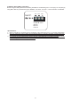
IP Address Setting(SW1~3 Operation): Before using the node, please set the existing E-NODE 8's IP addressing from 172.16.0.[0]~172.16.0.[255] by using SW1~SW3 as you desired. As per E-NODE 8, 172.16.0.0, 172.16.0.3, 172.16.0.255 are not available. SW1 SW2 SW3 456 456 456 23 9 01 23 78 78 9 01 78 23 Set IP: 9 01 [0~255]= A*100+B*10+C A=0~2 B=0~9 C=0~9 Special Notice: 1. When A*100+B*10+C exceeds 255, the IP address of the node will be set to 172.16.0.250 automatically. 2.
Part II X-Soft-Net Holding System & Operation Guide
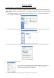
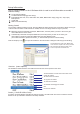
How To setup! Configuring your computer Ethernet card before installing To use E-NODE 8 to drive LED lightings from Elation as needed with X-Software software operation. Before using X-Software software, it is advisable to firstly configure your computer Ethernet card. The process is very simple and is described as the below instructions. It is necessary to set two parameters, the IP address and the Subnet Mask. 1. These settings are adjusted in the Windows Network Settings Dialogue.
Setup Information This is a setup software in the X-Software which is used to set all information as needed. It features mainly; To set Node IP Address To edit/Create Events(trigger time setup) Events(Flash files-*swf, *GVI, Video Files-*AVI,*WMV, MPEG Files-*mpeg,*mpg,*mlv, *mp2,*mp3) Backup/Load Create GVI DMX Control Mode Setup Getting Started For the setup software working correctly, all events MUST be firstly placed in the scene library called "Scene_lib" of the X-Soft main folder.
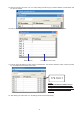
1a. Click the ''Show IP set Form'' icon, a IP setup dialog box will bring up to add IP address of nodes which will be used as needed. 1b. Enter a valid integer value of node quantity which will be used as needed in the entire system. Node quantity IP address of each node 1c. Enter an actual IP address of each node in IP Address bar. The actual IP address of each node is provided by us and labeled on the back of the node. 172.16.0.
Section_2: Events Editing/Creating(Events Trigger Time Setup) 2a. Events Edit/Create mode enables. All events(Flash files, Video Files, MPEG Files) which have been copied to the "Scene_lib" folder will automatically be listed and display in the Source Components Presentation List. Calendar Source Components Presentation List PC time(real-time clock) Start Time End Time Trigger mode 2b.
2g. Clicking the "Display Events" icon allows the user to preview these events which have been completed, and they will appear with individual start time and end time in the destination component list. Destination Components Presentation List All events(Flash files, Video Files, MPAG Files) which have been edited completely will be listed and appear with individual start time and end time in the Destination Components Presentation List. 2h. Click the "Exit" icon to exit the existing mode.
2.1.Firstly, select the "Scene_lib" folder as a destination which the user load more Flash files, Video Files, MPEG Files to, and click the "Load File" icon. 2.2 Define the folder with more Flash files, Video Files, MPEG Files which you wish to load, then secondly click the "load File" icon. Do this, all Flash files, Video Files, MPEG Files in this folder can be loaded to the Setup software together and saved in the "Scene _lib" folder for events use.
4a. Select one Event(Flash files, Video Files, MPEG Files) in the Source Component Presentation List, and click the "Add" icon for dummy GVI. 4b. To repeat the above step to add more events for dummy GVI as needed. In this option, click the "Insert" icon to insert events between two events as needed. Click the "DEL" icon to delete events which you want to cancel. 4c. Input a new GVI name in the file name bar, and click the "Save" icon to save the existing setting.
Section_4: DMX Control Mode Setup In this mode, all scenes/Events(Flash files, Video Files, MPEG Files) are available to be controlled and playback by addressing DMX address. And user may use DMX values to control the desired scenes.
How To Map! 1. Welcome! Thank you for your choosing X-Mapping of an innovative LED mapping software. X-Mapping has following functions: Create a mock map which defines the relationship between pixels on your computer screen and the actual device panels, bars, dots, chips or strips. After creating a map in X-Mapping, allows it to download and store in your computer. Configure the Art-net devices parameters as needed, i.e.
Help Menu: Help Menu will bring up a dialog box that includes the existing version number of the software. Zoom drop down menu can be used to move from 20% to 100% within the work grid. 4. Customizing Work Grid and Device Setup Directly click ''X-Mapping'' icon to get started, and the X-Mapping main setup dialog will show as following for you. Work Grid Add New Node is an option that is used to add new node as needed, respectively entering its name, total output ports and total channels per port.
5. Customizing Dummy Devices In the Edit/Add... option, it allows the user to choose, create or modify devices library list as needed Device Select is a drop down menu that displays existing device or Edit/Add option. Click the "Edit/Add" icon, a new dialog will show as following; Fixture Library List Adds a new dummy device Modifies an existing device which you wish to Deletes an existing device which you wish to 5.1. Click the "Add Device" icon, bring up a setup dialog box.
Total Pixels show the device pixels's information. After clicking OK, You can save your existing settings. And created device will be existing in the device library list. 5.2. If you're not satisfied these created devices's setting, or something else wrong happens, it allows the user to modify these settings. Click the "Modify" icon, bring up a setup dialog box.
6. Create a Pixel Map After all devices and fixtures settings are finished, access to built a pixel map as needed. Toolbar Existing Device Info Tab Device Select is a drop down menu that displays existing device which you wish to assign the device to the Pixel Map. Node Address is a drop down menu that displays existing nodes which you wish to use to control your devices actually.
HINT: In the event of some mistakes happen, user can modify them by pointing the device number with the mouse action. A new dialog box will display and enter a correct number, then click the ''OK'' icon to save. You MUST ensure overall pixels array order is matching with their scanning order which has been set up. 6.7. To repeat Step6.3.-6.6 to assign more output ports of the selected device. 6.8. To repeat Step6.2.-6.7 to assign more same nodes to control the fixtures.
6.9. After you're satisfied with overall settings, you can click the ''Convert Map Address'' icon to convert the pixel map addresses. Program Rate 6.10.and click the '' Save( )'' icon in the Toolbar save in the main folder as a LEDMap file for X-Software operation. It is advisable to save the LEDMap document in the main folder to for working correctly.
How to playback preset Scenes by running X-Software? Starting X-Software In the main folder, click the "Runproj"( will display the following screen for you; ) icon to start your X-Software.
Dimming Area Operation Node is a drop down menu that displays the actual IP address of each node. Outport is a drop down menu that displays the existing outport of the selected Node. Pixel is a drop down menu that displays the existing pixel map address of the selected Outport. Work Grid features to adjust the brightness Before running X-Software, it is advisable to check how many nodes are used to control the device and review all the settings in Mapping Operation. 1.
1.4 Select an existing pixel address of the selected outport. In the drop down menu, "Port_pixel_all" means all the pixels existing in selected outport, while "Node_Pixel_all" means all the pixels existing in selected node. 1.5 Adjust the brightness by moving the work grid. For example: A. Move Red work grid to 140. B. Move Master work grid to 142. C. The brightness of Red color is 142 x 140 = 77.96 255 1.
The user can follows the below flow to close the hard acceleration of your computer: Display Properties____> Settings____>advanced____>troubleshooting____>close Hard Acceleration DMX Triggering Function(DMX Control) In this mode, all scenes(Flash files-*swf, *GVI, Video Files-*AVI,*WMV, MPEG Files-*mpeg,*mpg,*mlv, *mp2, *mp3) are available to be controlled and playback by addressing DMX address. And user may use DMX values to control the desired scenes.
X-Net Configuration Software Operating Instruction (Software version:1.00) Enter frame value Enter IP address of the existing E-NODE 8 Getting started X-Driver Configuration Software (Ver1.00) In Windows, click the Start button and go to the "Programs" then "X-Net Configuration Software". Move the pointer to the X-Net Configuration Software icon, the X-Net Configuration Software screen appears hereinafter: 1.Toolbar Operation: 1.1 Click "OPEN FLASH" icon, a dialogue box will appear on the screen.
3.Show Option Operation: In the option, user can assign the SHOW in E-NODE 8. 3.1 "DIR" icon use to have files in E-NODE 8 readout and list. 3.2 "Read" icon used to read pointed file in E-NODE 8. 3.3 "Write" icon used to write files with extension .scn into E-NODE 8. 3.4 "Del" icon used to delete pointed files in E-NODE 8. 3.5 "Format" icon used to clear up all files in E-NODE 8. 3.6 "Edit Show" icon used to start and edit the SHOW in E-NODE 8. It is necessary to click the icon for SHOW readout in E-NODE 8.
4.Event Edit Option: In this option, the user can call up Time Trigger Mode for SHOW by editing show events to E-NODE 8, including Weekly Mode, Daily Mode and Date Mode. How to Edit show events? 4.1 To select your desired time trigger modes. 4.2 And select your desired trigger shows. 4.3 Then click the "ADD" icon to edit the desired time. 4.4 And click the Down Arrow under the "Event Start" icon to select the starting time of your desired show. 4.