E L A TI ON | ARENA PAR ZOOM™ | user manual 1.0 ARENA PAR ZOOM™ user manual 1.
w w w . e l a t i o n l i g h t i n g . c o m ©2013 ELATION PROFESSIONAL all rights reserved. Information, specifications, diagrams, images, and instructions herein are subject to change without notice. ELATION PROFESSIONAL logo and identifying product names and numbers herein are trademarks of ELATION PROFESSIONAL.
w w w . e l a t i o n l i g h t i n g .
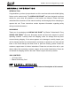
w w w . e l a t i o n l i g h t i n g . c o m GENERAL INFORMATION INTRODUCTION Congratulations, you have just purchased one of the most innovative and reliable lighting fixtures on the market today! The ARENA PAR ZOOM™ has been designed to perform reliably for years when the guidelines in this booklet are followed. Please read and understand the instructions in this manual carefully and thoroughly before attempting to operate this unit.
w w w . e l a t i o n l i g h t i n g . c o m CUSTOMER SUPPORT Elation Professional® provides a customer support line, to provide set up help and to answer any question should you encounter problems during your set up or initial operation. You may also visit us on the web at www.elationlighting.com for any comments or suggestions. For service related issue please contact Elation Professional®. Service Hours are Monday through Friday 8:00 a.m. to 5:00 p.m. PST.
w w w . e l a t i o n l i g h t i n g . c o m 2-YEAR LIMITED WARRANTY A. Elation Professional® hereby warrants, to the original purchaser, Elation Professional® products to be free of manufacturing defects in material and workmanship for a period of two years, (730 days) from the date of purchase. This warranty shall be valid only if the product is purchased within the United States of America, including possessions and territories.
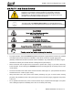
w w w . e l a t i o n l i g h t i n g . c o m SAFETY INSTRUCTIONS ™ The ARENA PAR ZOOM is an extremely sophisticated piece of electronic equipment. To guarantee a smooth operation, it is important to follow the guidelines in this manual. The manufacturer of this device will not accept responsibility for damages resulting from the misuse of this fixture due to the disregard of the information printed in this manual. This device falls under PROTECTION CLASS 1.
w w w . e l a t i o n l i g h t i n g . c o m GENERAL GUIDELINES • N E V E R O P E N T H I S F I X T U R E W H I L E I N U S E ! • During the initial operation of this fixture, a light smoke or smell may emit from the interior of the fixture. This is a normal process and is caused by excess paint in the interior of the casing burning off from the heat associated with the lamp and will decrease gradually over time.
w w w . e l a t i o n l i g h t i n g . c o m FIXTURE OVERVIEW 1: 3pin DMX IN 2: 3pin DMX OUT 3: 5pin DMX IN 4: 5pin DMX OUT 5: Menu Function Display 6: MENU Button 7: UP Button 8: DOWN Button 9: ENTER Button 10: Power ON 11: DMX Signal 12: PowerCON IN 13: PowerCON OUT 14: Fuse 1. 3pin DMX IN - DMX signal input 2. 3pin DMX OUT - DMX signal output 3. 5pin DMX IN - DMX signal input 4. 5pin DMX OUT - DMX signal output 5. Menu Function Display - Displays function menus and options 6.
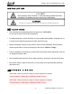
w w w . e l a t i o n l i g h t i n g . c o m INSTALLATION T he el ec tri c c onnec ti on m ust onl y b e c arri ed out b y a qu al if i ed el ec tri c i an. C A U T I O N S • The maximum recommended ambient temperature is 104°F (40°C). Do not use the fixture above this temperature. • For added protection, mount the fixture in areas outside walking paths, seating areas, or in areas were unauthorized personnel might reach the fixture.
w w w . e l a t i o n l i g h t i n g . c o m MOUNTING POINTS • Overhead mounting requires extensive experience, including amongst others calculating working load limits, installation material being used, and periodic safety inspection of all installation material and the device. If you lack these qualifications, do not attempt the installation yourself. Improper installation can result in bodily injury.
w w w . e l a t i o n l i g h t i n g . c o m UNDERSTANDING DMX DMX-512 DMX is short for Digital Multiplex. This is a universal protocol used by most lighting and controller manufactures as a form of communication between intelligent fixtures and controllers. DMX allows all makes and models of different manufactures to be linked together and operate from a single controller. This is possible as long as all the fixtures and the controller are DMX compliant.
w w w . e l a t i o n l i g h t i n g . c o m Be sure to follow the above figure when making your own cables. Do not use the ground lug on the XLR connector. Do not connect the cable’s shield conductor to the ground lug or allow the shield conductor to come in contact with the XLR outer casing. Grounding the shield could cause a short circuit and erratic behavior.
w w w . e l a t i o n l i g h t i n g . c o m DMX-512 CONNECTION WITH DMX TERMINATOR A DMX terminator should be used in all DMX lines especially in longer runs. The use of a terminator may avoid erratic behavior in your DMX line. A terminator is a 120 ohm 1/4 watt resistor that is connected between pins 2 and 3 of a male XLR connector (DATA + and DATA -). This fixture is inserted in the female XLR connector of the last fixture in your daisy chain to terminate the line.
w w w . e l a t i o n l i g h t i n g . c o m DMX ADDRESSING All fixtures should be given a DMX starting address when using a DMX controller, so the correct fixture responds to the correct control signal. This digital starting address is the channel number from which the fixture starts to “listen” to the digital control information sent out from the DMX controller.
w w w . e l a t i o n l i g h t i n g . c o m FIXTURE MENU ON-BOARD SYSTEM MENU The ARENA PAR ZOOM™ comes with an easy to navigate system menu. The next section will detail the functions of each command in the system menu. MENU FUNCTION DISPLAY To select any of the menu functions, press the MENU button until the desired function is displayed. Select the function by pressing the ENTER button and the display will flash. Use the DOWN and UP buttons to change the mode.
w w w . e l a t i o n l i g h t i n g . c o m 17 ARENA PAR ZOOM™ User Manual 1.
w w w . e l a t i o n l i g h t i n g . c o m MAIN FUNCTIONS DMX Address Select the DMX Address menu, then press the ENTER button and the display will flash. Use the DOWN and UP buttons to change the DMX Address (1-512), and then press the ENTER button to confirm selection. To return back to the previous menu functions without any change press the MENU button. Channel Mode Select the Channel Mode menu, then press the ENTER button and the display will flash.
w w w . e l a t i o n l i g h t i n g . c o m Back Light Select the Back Light menu, then press the ENTER button and the display will flash. Use the DOWN and UP buttons to select ON or OFF. Once the desired mode has been selected, press the ENTER button to confirm selection. To return back to the previous menu functions without any change press the MENU button. White Balance Select the White Balance menu, then press the ENTER button and the display will flash.
w w w . e l a t i o n l i g h t i n g . c o m DMX CHANNEL FUNCTIONS AND VALUES 20 ARENA PAR ZOOM™ User Manual 1.
w w w . e l a t i o n l i g h t i n g . c o m TROUBLE SHOOTING The following are a few common problems that may occur during operation, and some suggestions for easy troubleshooting: A. The unit does not work, no light and the fan does not work 1. Check the connection of power and main fuse. 2. Measure the mains voltage on the main connector. 3. Check the power on LED. B. Not responding to DMX controller 1. If DMX LED is not ON, check DMX connectors and cables to see if linked properly. 2.
w w w . e l a t i o n l i g h t i n g . c o m CLEANING AND MAINTENANCE CLEANING Frequent cleaning is recommended to insure proper function, optimized light output, and an extended life. The frequency of cleaning depends on the environment in which the fixture operates: damp, smoky or particularly dirty environments can cause greater accumulation of dirt on the fixture’s optics. • Clean the external lens surface at least every 20 days with a soft cloth to avoid dirt/debris accumulation.
w w w . e l a t i o n l i g h t i n g .
w w w . e l a t i o n l i g h t i n g . c o m PHOTOMETRIC DATA Please Note: Specifications and improvements in the design of this unit and this manual are subject to change without any prior written notice.
w w w . e l a t i o n l i g h t i n g . c o m DIMENSIONAL DRAWINGS Please Note: Specifications and improvements in the design of this unit and this manual are subject to change without any prior written notice.
w w w . e l a t i o n l i g h t i n g . c o m CIRCUIT SCHEMATICS Please Note: Specifications and improvements in the design of this unit and this manual are subject to change without any prior written notice.
w w w . e l a t i o n l i g h t i n g . c o m OPTIONAL ACCESSORIES ORDER CODE ITEM DESCRIPTION TRIGGER CLAMP Heavy Duty Wrap Around Hook Style Clamp PLC3 3-foot (1m) PowerCON Link Cable PLC6 6-foot (1.8m) PowerCON Link Cable PLC10 10-foot (3m) PowerCON Link Cable PLC15 15-foot (4.5m) PowerCON Link Cable AC3PDMX5PRO 5-foot (1.5m) 3-pin PRO DMX Cable AC3PDMX10PRO 10-foot (3m) 3-pin PRO DMX Cable AC3PDMX15PRO 15-foot (4.5m) 3-pin PRO DMX Cable AC3PDMX25PRO 25-foot (7.
w w w . e l a t i o n l i g h t i n g . c o m 28 ARENA PAR ZOOM™ User Manual 1.