ProTron LED USER MANUAL Version 2.
ProTron LED TABLE OF CONTENTS TABLE OF CONTENTS PREFACE About this Manual ........................................................................................................................................ 3 Included Items .............................................................................................................................................. 3 Accessories .............................................................................................................................
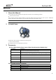
ProTron LED PREFACE 1. About this Manual The document provides installation and operation instructions for the following products: ProTron LED Luminaire Please read all instructions before installing or using this product. Retain this manual for future reference. Additional product information and descriptions may be found on the product specification sheet. Note: The ProTron LED Luminaire is universal voltage 100 to 240 VAC (auto-ranging). 2.
ProTron LED ProTron LED LUMINAIRE OVERVIEW 1.
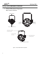
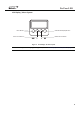
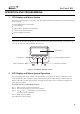
ProTron LED LCD Display / Menu System EXIT Button LEFT Arrow Button CHECK MARK(OK) Button RIGHT Arrow Button Figure 2: LCD Display & Menu System Note: For Menu operation and programming details, refer to "LCD Display and Menu System" on page 9.
ProTron LED INSTALLATION AND SET UP 1. Power Requirements The ProTron LED Luminaire operates on AC input voltages from 100 to 240 VAC. WARNING! This unit does not contain an ON/OFF switch. Always disconnect power input cable to completely remove power from unit when not in use. Note: The ProTron LED Luminaires has to be cooled down for 20min after it continuously works for 30 minutes. Keep working continuously will do great harm to the luminaire.
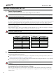
ProTron LED Table 2: ProTron LED Luminaire (IP65 Rated Models) AC Input Connections Back of Unit AC Input AC Output Figure 3: ProTron LED Luminaire AC Input & Output Connections CAUTION: In the event the AC input cable of this luminaire is damaged, it must be replaced, by the user, with an approved cable through an Authorized Dealer or Service Center. 3.
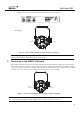
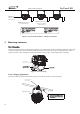
ProTron LED Luminaires ProTron LED DMX512 (from console or control device) DMX512 (out from first DMX512 (out to the next to second luminaire) luminaire or DMX512 controlled device) Figure 5: ProTron LED Luminaire - DMX512 Connections 4. Mounting Luminaire The ProTron LED Luminaires are designed to sit directly on its yoke assembly in a floor installation application.
ProTron LED OPERATION AND PROGRAMMING 1. LCD Display and Menu System The ProTron LED Luminaire’s LCD Display and Menu System provides local control for accessing the following fixture’s settings: Presets (Standard and User Defined) Fixture Settings Effects(Chases - preloaded and user defined) Current Fixture Operational Status Setting the DMX512 Address Note: If there are multiple luminaires in a system, changes would need to be made at each LCD Menu as desired.
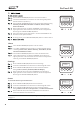
ProTron LED 3. Press CHECK MARK(OK)button to access Preset Select. Use LEFT and RIGHT arrow buttons to scroll through all presets and select Preset x(0 thru 31). ..Preset Edit 1. Intensity Press CHECK MARK(OK)button to select the desired menu among Intensity, Strobe Rate, Duration and Effects, Zone1, Zone2, Zone3 and Zone4. Once at desired preset, use LEFT and RIGHT arrow buttons to adjust parameter value as desired. Once all values are adjusted as desired, press CHECK MARK(OK)button.
ProTron LED 4.
ProTron LED 5. Dimming Curve Selection Through the menu, you are able to select one of four dimming curves: Linear Curve PL_Curve S_Curve Square Curve 0 Lumen Output PL_Curve * Lumen Output Linear Curve DMX Value 0 DMX Value *PL Curve follows the dimming curve of Philips Selecon PL series LED luminaries.
ProTron LED 6. Master / Slave Operational Mode The Master / Slave Operational Mode allows one ProTron LED Luminaire to act as the "Master" unit and all other connected units are controlled by this unit. When a unit is set to "Slave" mode, it will only listen to and follow any commands sent from a "Master" unit. Only one "Master" unit is allowed in this type of operation. To setup a master / slave network: Step 1. Set the first device in the DMX512 chain to Master Mode through the unit’s menu system. Step 2.
ProTron LED DMX CONTROL This section contains information for operating the luminaire using DMX control in Single Channel, Three Channel, Four Channel, 16-bit Control and Zone Mapping modes. For Menu options and detailed information, see "LCD Display and Menu System" on page 9. Note: These tables assume a DMX start address of 1. When a different starting address is used, this address becomes channel 1 function and other functions follow in sequence. 1.
ProTron LED 3. Four Channel Mode Table 5 provides DMX channel mapping of all DMX512 control values when the ProTron LED Luminaire is in Four Channel mode (as set by the luminaire’s menu system). Table 5: ProTron LED Luminaire DMX Channel Mapping (Four Channel Mode) 1 Intensity 2 Strobe Duration 8 bit control for Intensity of LED settings. Strobe's duration,Range is 0-255 White light mode (when strobe rate is also at 255) Please refer to the Strobe Duration Detail. Strobe rate slow to fast.
ProTron LED 4. 16-Bit Mode Table 6 provides DMX channel mapping of all DMX512 control values when the ProTron LED Luminaire is in 16-Bit Mode (as set by the luminaire’s menu system). Table 6: ProTron LED Luminaire DMX Channel Mapping (16-Bit Control Mode) 1 Instensity High 0-65535 0-100% 2 Instensity Low 0-255 0-100% 3 Effects 0-255 0 0-100% DMX 0 16 bit control for Intensity of LED settings. Controls strobe operations as follows . . .
ProTron LED 5. Custom Mode Table 7 provides DMX channel mapping of all DMX512 control values when the ProTron LED Luminaire is in Custom Mode (as set by the luminaire’s menu system).
ProTron LED 6. Zone Mapping Mode Table 8 provides DMX channel mapping of all DMX512 control values when the ProTron LED Luminaire is in Zone mapping Mode (as set by the luminaire’s menu system). Table 8: ProTron LED Luminaire DMX Channel Mapping (Zone Mapping Mode) 1 Master Intensity Hight 2 Master Intensity Low 0 - 65535 0 - 100% 0 16 bit control for Intensity of LED settings. 3 Effects 0 - 255 0 - 100% 0 Effects.
ProTron LED Table 11: ProTron LED Luminaire RDM Parameters IDs Get Allowed Set Allowed RDM Parameter IDs Value Comment Implemented Category - Network Management DISC_UNIQUE_BRANCH 0x0001 ■ DISC_MUTE 0x0002 ■ DISC_UN_MUTE 0x0003 ■ ■ PROXIED_DEVICES 0x0010 ■ PROXIED_DEVICES_COUNT 0x0011 COMMS_STATUS 0x0015 ■ ■ Category - Status Collection ■ QUEUED_MESSAGE 0x0020 ■ ■ STATUS_MESSAGES 0x0030 ■ ■ STATUS_ID_DESCRIPTION 0x0031 ■ CLEAR_STATUS_ID 0x0032 ■ SUB_DEVICE_STATUS_REP
ProTron LED Table 11: ProTron LED Luminaire RDM Parameters IDs Get Allowed Set Allowed RDM Parameter IDs Value ■ RECORD_SENSORS 0x0202 Comment Implemented Category - Dimmer Settings 0x03xx - FUTURE USE Category - Power / Lamp Settings 0x04xx ■ ■ DEVICE_HOURS 0x0400 ■ ■ LAMP_HOURS 0x0401 ■ ■ LAMP_STRIKES 0x0402 ■ ■ LAMP_STATE 0x0403 ■ ■ LAMP_ON_MODE 0x0404 ■ ■ DEVICE_POWER_CYCLES 0x0405 Category - Display Settings 0x05xx ■ ■ DISPLAY_INVERT 0x0500 ■ ■ DISPLAY_LEVEL 0x
ProTron LED Table 13: ProTron LED Luminaire RDM Manufacturer Specific PIDs for Root Device Get Allowed Set Allowed RDM Parameter IDs Type Length Unit Prefix Min Max Default Description Category - Manufacturer Defined PIDs - Range is 0x8000-0xffdf (See ANSI E1.
ProTron LED CLEANING AND CARE WARNING! All cleaning should be performed with power completely removed from the luminaire. Never remove protective covers when luminaire is powered. Wear appr opriate protective eye wear and gloves when cleaning the fixture. All service and maintenance, other than described herein, should be performed by a qualified technician or Authorized Service Center. 1.
ProTron LED TECHNICAL SPECIFICATIONS 1. ProTron LED Luminai re Operational Specifications Source: Beam Angle: Light Output: Color Temperature: Input Voltage (AC): Current (AC): Frequency: Control Protocols: Ambient Temperature: Humidity: Cooling: CW LED Array 120 Degrees > 28,000 lumens 6500K 100V to 240V (+/- 10%, auto-ranging)(120V, 50/60Hz is for US and Canada Only) 1.5 Amps (100V) / 0.
ProTron LED Appendix I Table 14: ProTron LED Luminaire Strobe Rate Details 24
ProTron LED Table 14: ProTron LED Luminaire Strobe Rate Details 25
ProTron LED Table 14: ProTron LED Luminaire Strobe Rate Details 26
ProTron LED Table 14: ProTron LED Luminaire Strobe Rate Details 27
ProTron LED Table 14: ProTron LED Luminaire Strobe Rate Details 28
ProTron LED Table 14: ProTron LED Luminaire Strobe Rate Details 29
ProTron LED Appendix II Table 15: ProTron LED Luminaire Strobe Duration 30
ProTron LED Table 15: ProTron LED Luminaire Strobe Duration 31
ProTron LED Table 15: ProTron LED Luminaire Strobe Duration 32
ProTron LED Table 15: ProTron LED Luminaire Strobe Duration 33
ProTron LED Table 15: ProTron LED Luminaire Strobe Duration 34
ProTron LED Table 15: ProTron LED Luminaire Strobe Duration Appendix III Table 16: ProTron LED Luminaire Effects Details 35