50x50 cookers EC 530 EC 560 86x50 cookers EC EC EC EC EC EC EC EC 830 832 860 861 862 960 961 930 Instruction for the use Installation advice
Dear Customer, We thank you very much for choosing our products. The instructions and advice included in this booklet are given to safeguard your safety and to use this appliance correctly. Be so kind as to keep this booklet. It will be useful to clear any doubt concerning its operation. This appliance must be only assigned to the use for which it has been realized, that is for cooking food. Any other use has to be considered incorrect and therefore dangerous.
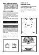
1 - COOKING HOBS GAS COOKING HOBS 2 (Fig. 1.1- 1.2 - 1.3) 1 GENEREAL FEATURES: 1. 2. 3. 4. 5. 3 Auxiliary burner (A) - 900 W Semi-rapid burner (SR) - 1550 W Rapid burner (R) - 2550 W Double-ring burner (DR) - 3500 W Electrical plate Ø 180 - 1500 W 4 Fig. 1.1 2 1 3 4 Fig. 1.2 2 1 5 3 4 Fig. 1.
2 - CONTROL PANEL Fig. 2.1 5 1 2 3 4 9 Fig. 2.2 10-11 6 5 1 2 1 3 4 Fig. 2.3 2 3 4 9 Fig. 2.4 6 10-11 1 2 7 3 4 8 9 Fig. 2.5 6 10-11 1 2 3 4 8 9 CONTROLS DESCRIPTION 4 1. 2. 3. 4. 5. 6. 7. Rear left burner control knob Front left burner control knob Front right burner control knob Rear right burner control knob Gas oven control knob Electrical oven control knob Electrical plate control knob (*) 8. 60' Timer control knob (*) 9.
3 - USE OF THE HOB BURNERS Each burner is controlled by a gas tap assuring the opening and the closing of the gas supply. Make the indicator of the knob the symbols printed on the control panel: - symbol ● : off - symbol : full on (nominal rate) - symbol : reduced rate To open the tap, which allows the flow of gas to the burner, push the knob and turn it towards the left. To turn it off, turn the knob towards the right up the safety click.
MODELS WITH BATTERY IGNITION - If the electronic ignition does not work make sure that the battery, installed on the back of the cooker, is not flat and has been installed correctly (see the chapter “Battery installation”, page 19). CHOICE OF THE BURNER CORRECT USE OF DOUBLE-RING BURNER The flat-bottomed pans are to be placed directly onto the pan-support. To use the WOK you need to place the proper stand in order to avoid any faulty operation of the double-ring burner (Fig. 3.
HOTPLATES CORRECT USE OF THE ELECTRICAL PLATES NORMAL HOTPLATES In using the hotplates you must: To switch on the normal hotplate, turn the knob (Fig. 3.6) onto the desired position; the numbers 1 to 6 indicate the working positions with the increase of temperature according to the number. Once boiling point has been reached, reduce the input according to the heating intensity desired, keeping in mind that the plate will continue to heat for 5 minutes after having been turned off.
NORMAL AND RAPID PLATES Position of switch TYPE OF COOKING 0 Switched OFF 1 2 For melting operations (butter, chocolate). 2 To maintain food hot and to heat small quantities of liquid (sauces, eggs). 3 To heat bigger quantities; to whip creams and sauces. (vegetables, fruits, soups). 4 3 4 Slow boiling, i.e.: boiled meats, spaghetti, soups, continuations of steam cooking of roasts, stews, potatoes. 5 4 For every kind of frying, cutlets, uncovered cooking, i.e.: risotto.
4 - GAS OVEN The glass of the oven door reaches high temperatures during operation. Keep children away. For child safety, a door guard can be fitted to prevent contact with the hot glass. The door guard is supplied as an accessory on request. Contact our Service Centre and indicate the relevant appliance model.
OVEN BURNER THERMOSTAT The numbers 1 to 10 (fig. 4.3) indicate the increasing oven temperature value (see table 4.4). To regulate the temperature, set the knob indicator onto the chosen number. OVEN COOKING To cook, before introducing the food, pre-heat the oven to the desired temperature for the period of time indicated on the table to left (table 4.4). These preheating times indicate the time that a cold and empty oven takes to reach that temperature.
GRILL BURNER USE OF THE GRILL This burner makes the stainless steel wire net red hot, which, generating infra red rays, permits grilling. Very important: the grill must always be used with the oven door slightly open (Fig. 4.7). Mount shield “A” which serves to protect the control panel from the heat. Turn on the grill, as explained in the preceding paragraphs and let the oven preheat for about 5 minutes with the door slightly open.
USE OF THE ROTISSERIE OVEN LIGHT Very important: the rotisserie must always be used with the oven door slightly open and with shield "A” mounted (Fig. 4.7). – Insert the dripping pan into the lowest rack holders of the oven and insert the rod support into the intermediate rack holders. – Put the meat to be cooked onto the rod, being careful to secure it in the center with the special forks.
5 - ELECTRICAL CONVECTION OVEN The glass of the oven door reaches high temperatures during operation. Keep children away. For child safety, a door guard can be fitted to prevent contact with the hot glass. The door guard is supplied as an accessory on request. Contact one of our dealers or Service Centre and indicate the relevant appliance model. GENERAL FEATURES The oven is furnished completely clean; it is advisable, however, upon first use, to turn the oven on to the maximum temperature (pos.
OVEN LIGHT The oven is equipped with a light that illuminates the oven to enable visually controlling the food that is cooking. This light is controlled by a switch on the control panel (fig. 5.3). For orientative purposes only, some oven cooking indications are shown on the following table: OVEN COOKING THERMOSTAT POSITION DISHES To cook, before introducing the food, preheat the oven to the desired temperature for the amount of time indicated in table 5.2.
A ROTISSERIE Except for some models, the ovens are equipped with a rotisserie for cooking on the spit using the grill. This device is made up of: – an electrical motor mounted on the rear part of the oven – a stainless steel rod, equipped with a detachable athermic grip and 2 recordable forks – a rod support to be inserted into the central rack holders of the oven. The rotisserie motor is operated by the switch indicated by the symbol on the control panel (fig. 5.2). Fig. 5.4 USE OF THE ROTISSERIE Fig.
6 - TIMER MECHANICAL TIMER The timer is equipped with a time buzzer and may be regulated for a maximum period of 60 minutes. The regulating knob (fig. 6.1) must be turned in a clockwise direction until it reaches the 60 minutes position and then turned to the desired time by turning the knob in a counterclockwise direction. 1 0 0 5 2 0 0 4 30 Fig. 6.
7 - GENERAL ADVICE * When the appliance is not being used, it is advisable to keep the gas tap closed. From time to time check to make sure that the flexible tube that connects the gas line or the gas cylinder to the appliance is in perfect condition and eventually substitute it, if it shows signs of wearing or damage. * The periodical lubrification of the gas taps must be done only by specialized personnel. In case of difficulty in the gas taps operation, call Service.
8 - CLEANING AND MAINTENANCE Always switch the cooker off at the mains isolating switch before cleaning or touching any electrical part. GENERAL ADVICE It is advisable to clean when the appliance is cold and especially for cleaning the enamelled parts. Avoid leaving alcaline or acidic substances (lemon juice, vinegar, etc.) on the surfaces. Avoid using cleaning products with a chlorine or acidic base.
6 - BATTERY INSTALLATION BATTERY INSTALLATION Models with battery ignition INSTALLING THE BATTERY Insert a type C battery (1.5 Volt) into the battery compartment on the back of the cooker (fig. 8.2). This battery is the power supply for the electronic ignition of gas burners. Batteries last on average for about two years (alkaline battery) depending on how often the electronic ignition is used. Notes for battery installation or replacement: Fig.8.2 - Only use a type C 1.5 Volt battery.
Advice for the installer LOCATION The cooker has “type X” or “Class 1”overheating protection so that it can be installed next to a cabinet whose height is greater than that of the cooker. 500 mm 800 mm It is advisable that the kitchen furniture near the sides of the cooker is made of heat resistant material, minimum 75 °K. 500 mm m 20 m m 20 m 20 Fig. 8.
500 mm 800 mm 500 mm GAS OVEN Class 1 20 mm Fig. 8.4b 500 mm 800 mm 20 mm 500 mm IC ELECTR OVEN Type X Fig. 8.
CHOOSING SUITABLE SURROUNDINGS Extractor hood for products of combustion In the room chosen to accommodate the gas appliance, there must be an adequate natural draft to allow combustion of the gas. The natural draft must be produced directly by one or more vents made in the external walls and providing a total opening of at least 100 cm2.
11 - GAS SECTION The walls adjacent to the oven must be of material resistant to heat. GASES The gases used for the operation of cooking appliances may be grouped by their characteristics into two types: – L.P.G. (in cylinders) – NATURAL GAS – TOWN GAS INSTALLATION The appliance is predisposed and adjusted to operate with the gas indicated on the specifications plate applied onto the appliance.
These operations must be carefully fulfilled as follows. 1 - GAS CONNECTION – Connect the cooker to the gas mains utilizing rigid or flexible pipes. – The connection must be executed to the rear of appliance (fig. 11.1); the pipe do not cross the cooker. – The unused end inlet pipe of the cooker (left or right) must be closed with the plug interposing the gasket. L.P.G. (G30/G31) – If not mounted, fit up the holder “R” to the holder “M” interposing gasket “Q”.
GAS CYLINDER CONNECTION The connection between the hose connector on the cooker and the regulator of the gas cylinder must be made using a 60 cm long flexible hose conforming to applicable standards, and hose clamps. The connection hose must be inserted in the hose support (fig. 11.4) and pushed over the hose connectors to the full depth.
2 - INJECTORS REPLACEMENT OF TOP BURNERS To replace the injectors, raise the cooktop in the following manner (fig. 11.5): – Litf the cooking top (fig. 11.5) – Fully raise the adjusting air tube A (fig. 14.4) in order to easily reach the injector. – Loose the screw “M” of each injector and fully raise the adjusting air tube “A” (fig. 11.6). – By a polygonal 7 spanner, remove the injector “J” from their housing and replace it by the proper one according to the kind of gas (see injectors table).
4 - ADJUSTMENT OF THE MINIMUN OF THE TOP BURNERS Considering that in the minimum position the flame must have a length of about 4 mm and must remain lit even with a brusque passage from the maximum position to that of minimum. The flame adjustment is done in the following way: – Turn on the burner – Tum the tap to the MINIMUM position – Take off the knob – With a small flat screwdriver turn the screw inside the tap rod to the correct regulation (fig. 11.7).
TABLE FOR THE CHOICE OF THE INJECTORS INCREASE OF AIR NECESSARY FOR GAS COMBUSTION (2 m3/h kW) Air necessary for combustion [m3/h] 1,80 3,10 6,10 5,10 6,40 4,00 BRULEURS Auxiliary (A) Semi-rapid (SR) Rapid burner (R1) Rapid burner (R2) Thermostat oven Grill TABLE FOR THE CHOICE OF THE INJECTORS G 30 – 30 mbar (L.P.G.
5 - REPLACEMENT OF THE OVEN BURNER INJECTOR 6 - REPLACEMENT OF THE GRILL BURNER INJECTORS According to the type of gas, the oven injectors are to be similarly replaced, as stated on the table of the paragraph 2, operating as follows: – remove the oven bottom – unscrew the burner fixing screw (Fig. 11.9) – slip the burner itself from the oven (Fig. 11.10) – remove the injector from the connection and replace it with the proper one – remove the grill burner by unscrewing the front screws (fig. 14.
7 - PRIMARY AIR OF THE OVEN BURNER 8 - PRIMARY AIR OF THE GRILL BURNER With a screwdriver untighten the two screws (fig. 14.10 and move forward or backward to close or open the air flow, the air ring according to the Air Adjustment Table. Light the burner and check the flames. With a screwdriver untighten the screw (fig. 14.11) and turn the air ring to close or open the air flow, according to the Air Adjustment Table. Light the burner and check the flames. Fig. 11.
9) REGULATING OF THE OVEN MINIMUM To be effected only for the oven burner (as the grill burner has an only fixed input) operating on the thermostat as follows: – Light the oven taking the knob to position 10 (max) – remove the knob and by a thin screwdriver (3 mm section - 100 mm long) unscrew of about a half turn the bypass, passing through the front panel hole (see picture below) – fit the knob and let the oven heat for 10 minutes, then take the knob to position 1 allowing the thermostat to work under by-
12 - ELECTRICAL SECTION IMPORTANT: The cooker must be installed in accordance with the manufacturer’s instructions. Incorrect installation, for which the manufacturer accepts no responsibility, may cause damage to persons, animals and things. GENERAL – The cooker is supplied without a power supply plug and therefore if you are not connecting directly to the mains, a standardized plug suitable for the load must be fitted.
CONNECTING FEEDER CABLE To connect the feeder cable to the cooker it is necessary to: Before effecting any intervention on the electrical parts of the appliance, the connection to the network must be interrupted. – Remove the screw that hold shield “A” behind the oven (fig. 12.1). – Insert the feeder cable of the suitable section (see Feeder Cable Section) into the cable clamp “D”. – Connect the phase cables to terminal “B”. – Pull the feeder cable and block it with cable clamp “D”. – Re-mount shield “A”.
REPAIRS Before effecting any intervention on the electrical parts of the appliance, the connection to the network must be interrupted. REMPLACEMENT OF ELECTRICAL COMPONENTS SITUATED UNDER THE COOKTOP Switches and thermostats, igniter and electrodes can be replaced after lifting the cooktop, following the instructions shown in the chapter “REPLACEMENT OF THE INJECTORS OF THE TOP BURNERS”.
Identification label 35
Descriptions and illustrations in this booklet are given as simply indicative. The manufacturer reserves the right, considering the characteristics of the models described here, at any time and without notice, to make eventual necessary modifications for their construction or for commercial needs. Cod.