Instructions for the use - Installation advices GAS COOKERS Models: EGC 533 WH, EGC 533 CM, EGC 533 LG % ELBA QUALITY 100 MADE IN ITALY HOME APPLIANCES Made in Italy
Dear Customer, Thank you for having purchased and given your preference to our product. The safety precautions and recommendations reported below are for your own safety and that of others. They will also provide a means by which to make full use of the features offered by your appliance. Please preserve this booklet carefully. It may be useful in future, either to yourself or to others in the event that doubts should arise relating to its operation.
IMPORTANT SAFETY PRECAUTIONS AND RECOMMENDATIONS IMPORTANT: This appliance is designed and manufactured solely for the cooking of domestic (household) food and is not suitable for any non domestic application and therefore should not be used in a commercial environment. The appliance guarantee will be void if the appliance is used within a non domestic environment i.e. a semi commercial, commercial or communal environment. Read the instructions carefully before installing and using the appliance.
• • • • • • • • • 4 manner in accordance to health and environmental protection regulations, ensuring in particular that all potentially hazardous parts be made harmless, especially in relation to children who could play with unused appliances. The various components of the appliance are recyclable. Dispose of them in accordance with the regulations in force in your country. After use, ensure that the knobs are in the off position.
• • • • • • • • • • • • WARNING: When correctly installed, your product meets all safety requirements laid down for this type of product category. However special care should be taken around the rear or the underneath of the appliance as these areas are not designed or intended to be touched and may contain sharp or rough edges, that may cause injury.
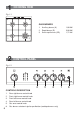
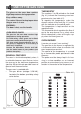
1 COOKING HOB Fig. 1.1 3 3 GAS BURNERS 1. Auxiliary burner (A) 1,00 kW 2. Rapid burner (R) 3,00 kW 3. Semi-rapid burner (SR) 1,75 kW 2 1 2 CONTROL PANEL Fig. 2.1 5 4 3 2 CONTROLS DESCRIPTION 6 1. Rear right burner control knob 2. Front right burner control knob 3. Front left burner control knob 4. Rear left burner control knob 5. Gas oven control knob 6.
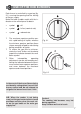
3 USE OF THE HOB BURNERS Each burner is controlled by a gas tap (fig. 3.1) assuring the opening and the closing of the gas supply. Make the knob symbols match with the indicator on the control panel to obtain: • symbol : off • symbol : full on (nominal rate) • symbol : reduced rate √√ √√ √√ The maximum aperture position permits rapid boiling of liquids, whereas the minimum aperture position allows slower warming of food or maintaining boiling conditions of liquids. Fig. 3.
LIGHTING THE BURNERS CHOICE OF THE BURNER To ignite the burner, the following instructions are to be followed: On the control panel, near every knob, there is a diagram that indicates which burner is controlled by that knob. 1. 2. 3. Press in the corresponding knob and turn counter-clockwise (fig. 3.2 ) to the full flame position marked by the (full on) symbol (fig. 3.1). Press the ignition button marked by the symbol (fig. 3.3).
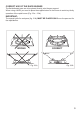
CORRECT USE OF THE RAPID BURNER The flat-bottomed pans are to be placed directly onto the pan-support. When using a WOK you need to place the supplied stand in the burner to avoid any faulty operation of the rapid burner (Fig. 3.5a - 3.5b). IMPORTANT: The special grille for wok pans (fig. 3.5b) MUST BE PLACED ONLY over the pan-rest for the rapid burner. WRONG CORRECT Fig. 3.5a Fig. 3.
4 USE OF THE GAS OVEN The glass on the oven door reaches high temperatures during operation. Keep children away. The cooker lid must be kept open when the gas oven is in use. WARNING: The door is hot, use the handle. OVEN DOOR GUARD The glass on the oven door reaches high temperatures during operation. For child safety, a door guard can be fitted to prevent contact with the hot glass. The door guard (thermoreflective door inner glass) is supplied as an accessory at extra cost, if required.
IGNITION OF THE OVEN BURNER COOKING EXAMPLES ATTENTION: Never turn the control knob before opening the oven door. Temperatures are approximate as they vary depending on the quality and amount of food. Remember to use ovenproof dishes and to adjust the oven temperature during cooking if necessary. To ignite the oven burner: 1. Open the oven door to the full extent. WARNING: Risk of explosion! The oven door must be open during this operation. 2.
5 CLEANING AND MAINTENANCE GENERAL ADVICE ENAMELLED PARTS • When the appliance is not being used, it is advisable to keep the gas tap closed. • The periodical lubrication of the gas taps must be done only by specialized personnel. • If a tap becomes stiff, do not force; contact your local After Sales Service Centre. All the enamelled parts must be cleaned with a sponge and soapy water or other non-abrasive products. Dry preferably with a microfibre or soft cloth.
GAS TAPS BURNERS Periodic lubrication of the gas taps must be carried out by specialist personnel only. In the event of operating faults in the gas taps, call the Service Department. They can be removed and washed with soapy water only. They will remain always perfect if cleaned with products used for silverware. After cleaning or wash, check that burnercaps and burner-heads are dry before placing them in the respective housings.
Advice for the installer IMPORTANT 14 • Cooker installation must only be carried out by QUALIFIED TECHNICIANS and in compliance with local safety standards. Failure to install the appliance correctly could invalidate any manufacturer’s warranty. • The appliance must be installed in compliance with regulations in force in your country and in observation of the manufacturer’s instructions. • Some appliances are supplied with a protective film on steel and aluminium parts.
6 INSTALLATION The cooker affords class “1” protection against overheating of surrounding surfaces. The installation conditions, concerning protection against overheating of the surfaces adjacent to the cooker, must conform to Figs. 6.1 and 6.2. A space of at least 2 cm must be left between the cooker and any adjacent furniture, which must not exceed the height of the cooktop.
VENTILATION REQUIREMENTS The appliance must be installed in compliance with applicable local regulations concerning ventilation and the evacuation of exhaust gases. Intensive and prolonged use may require extra ventilation, e.g. opening a window, or more efficient ventilation increasing the mechanical suction power if this is fitted.
7 GAS SECTION GAS INSTALLATION REQUIREMENTS Important ! • The walls adjacent to the cooker must be of heat-resistant material. • Before installation, make sure that the local distribution conditions (gas type and pressure) and the adjustment of this appliance are compatible. The appliance adjustment conditions are given on the plate or the label. • This appliance must be installed and serviced only by a suitably qualified, registered installer.
Fig. 7.1 ok ok THE PIPE DOES NOT CROSS THE REAR PANEL OF THE COOKER. IN CASE OF CROSSING THE BACK PANEL, ENSURE THE PIPE IS POSITIONED CLOSE TO THE BOTTOM PART OF THE APPLIANCE. POSSIBLE GAS CONNECTIONS GAS CONNECTION WITH A RUBBER HOSE Important! A rubber hose connection shall only be made if permitted by the applicable local regulations.
3. 4. Make sure that the hose is tightly and securely fitted at both ends. Use a standard hose clamp (not supplied) to fasten the hose. Connecting the cooker to LPG 1. If not already fitted, fit the LPG hose holder on the inlet pipe, making sure that you place the sealing washer between them (as shown in Fig. 7.2). Important! The LPG hose holder is composed by Natural/Town gas hose holder with LPG hose adapter screwed at the bottom end (interposing the proper sealing washer between them). 2.
Gas connection with rubber hose holders Note: if not already fitted on the inlet pipe, the hose holders are supplied with the product in a separate kit.
• • • • • • • • the flexiple pipe does not exceed 2000 mm in length (or refer to applicable local regulations) and does not come into contact with sharp edges, corners or moving parts. Use a single flexible pipe only; never connect the cooker with more than one flexible pipe. the flexible pipe can easily be inspected along its entire length to check its condition; if it has an expiry date, it should be replaced before that date.
• IMPORTANT 22 0,85 86 77 Fully open(*) 130 129 101 - Ø injector [1/100 mm] Ring opening [mm] 5 (*) - - - Ring opening [mm] Natural Gas G20 20 mbar Air necessary for combustion [m3/h] 2,00 3,50 6,00 6,40 BURNERS Auxiliary (A) Semi-rapid (SR) Rapid (R) Oven 5 (*) 270 - 280 192 145 Ring opening [mm] Town Gas G110 8 mbar Ø injector [1/100 mm] AIR VENT NECESSARY FOR GAS COMBUSTION = (2 m3/h x kW) (*) = Reference value 3,20 Oven 87 0,75 3,00 Rapid (R) 50 66 0,40 1,75 Ø
REPLACEMENT OF THE INJECTORS If the injectors are not supplied they can be obtained from the “Service Centre”. J Select the injectors to be replaced according to the “Table for the choice of the injectors”. The nozzle diameters, expressed in hundredths of a millimetre, are marked on the body of each injector. REPLACEMENT OF THE INJECTORS OF THE COOKTOP BURNERS Fig. 7.4 To replace the injectors proceed as follows: • Remove pan supports and burners from the cooktop.
OPERATIONS TO BE EXECUTED FOR THE REPLACEMENT OF THE INJECTOR OF THE OVEN BURNER • Lift and remove the lower panel inside the oven. • Remove the burner securing screw (fig. 7.6). • Withdraw the burner as shown in figure 7.7 and rest it inside the oven. Take care not to damage the wire to the safety valve probe. • Using a 7 mm box spanner, unscrew the injector (indicated by the arrow in fig. 7.7) and replace it by the proper one according to the kind of gas.
Flame faulty in primary air Flame correct Flame with excess primary air long, yellow and trembling clear interior blue cone short and sharp too blue interior cone tending to detach air regulating tube, too closed correct distance of the tube CAUSE air regulating tube, too open ADJUSTMENT OF THE OVEN BURNER MINIMUM Considering that in the minimum position the flame must have a length of about 4 mm and must remain lit even with a brusque passage from the maximum position to that of minimum.
8 BATTERY INSTALLATION INSTALLING THE BATTERY Insert a type C battery (1.5 Volt) into he battery compartment on the back of the cooker (fig. 8.1). This battery is the power supply for the electronic ignition of gas burners (cooktop burners only). Batteries last on average for about two years (alkaline battery) depending on how often the electronic ignition is used. Notes for battery installation or replacement: • Only use a type C 1.5 Volt battery. • Check for correct polarity (fig. 8.
The manufacturer cannot be held responsible for possible inaccuracies due to printing or transcription errors in the present booklet. The manufacturer reserves the right to make all modifications to its products deemed necessary for manufacturer commercial reasons at any moment and without prior notice, without jeopardising the essential functional and safety characteristics of the appliances. HOME APPLIANCES Made in Italy Cod.